Technology researchers and makes it freely available over the web where possible.
This is an author-deposited version published in: https://sam.ensam.eu Handle ID: .http://hdl.handle.net/10985/7340
To cite this version :
Fabien MEINGUET, Eric SEMAIL, Xavier KESTELYN, Yves MOLLET, Johan GYSELINCK - A change-detection algorithm for short-circuit fault detection in closed-loop AC drives - IET Electric Power Applications - Vol. 8, n°5, p.pp.165-177 - 2014
Any correspondence concerning this service should be sent to the repository Administrator : archiveouverte@ensam.eu
1
A change-detection algorithm for short-circuit fault
detection in closed-loop AC drives
F. Meinguet
1E. Semail
1Kestelyn
1Y. Mollet
2J. Gyselinck
21
ENSAM – Lille, Laboratoire d’Electrotechnique et d’Electronique de Puissance de Lille
8 Bd Louis XIV – 59046 Lille, France
2
Université libre de Bruxelles (ULB), BEAMS department, Avenue Franklin Roosevelt 50 (CP165/52),
B-1050 Brussels, Belgium
E-mail:
Fabien.Meinguet@ensam.eu
Abstract: This paper deals with an on-line method for turn-to-turn short-circuit fault detection in low-voltage
permanent-magnet synchronous machine drives. Due to the closed-loop control, the fault effects are reflected in the voltage. Therefore, an appropriate diagnostic index is proposed, which is derived from the positive- and negative-sequences of the voltage references. These sequences are obtained in the time domain via adaptive filters, which require only a few calculations. To increase the sensitivity to the fault, the algorithm is only applied to a part of the voltage references, i.e. the output of the proportional-integral controllers. Further, the cumulative-sum algorithm is introduced to cope with changes of small magnitudes. This algorithm allows a change of a fault index to be detected and can be used as a decision system. The resulting fault detection scheme is computationally cheap and can be embedded in the control unit. Simulations and experimental results validate the proposed method in steady state and the performances under non-stationary operating conditions are also investigated.
Nomenclature
Minimum fault amplitude due to the shorted turns to be detected
Fault detection delay
Additional dq-axis voltages due to the shorted turns
Electrical position
Ratio of shorted turns compared with the number of turns in series within one phase
Bandwidths of the dq-axis closed-loop transfer functions
Variance of the fault index
Magnitude of the fundamental component of the flux linkage due to the permanent magnets
Mechanical pulsation
2
abc Subscripts related to natural quantities
Subscripts related to stator frame quantities
dq Subscripts related to rotor frame quantities
Superscript related to the positive-sequence component
Superscript related to the negative-sequence component
Superscript related to the controller references
Clarke transformation matrix
Rotation matrix
dq-axis transfer function of the PI controllers
Transfer function of the direct adaptive filter
Electromotive force expressed in xy(z) frame
CUSUM function
Threshold of the decision system
Phase currents expressed in xy(z) frame
Damping factor of the direct and quadrature adaptive filters
Proportional gain of the dq-axis PI controllers
Integral gain of the dq-axis PI controllers
Inductance matrix
dq-axis inductances
Mean value of the fault index in healthy condition
3
Probability density function of the healthy distribution
Probability density function of the faulty distribution
Phase-shift operator ( )
Transfer function of the quadrature adaptive filter
Fault resistance
Fault index (ratio of the negative- to positive-sequence voltages)
Stator resistance
Laplace variable
Sampling period
Stator voltages expressed in xy(z) frame
Stator voltages expressed in xy(z) frame upon the occurrence of an inter-turn fault
CUSUM Cumulative sum
LLR Log-likelihood ratio
1. Introduction
Fault detection and diagnosis are paramount for optimizing the availability of electrical drives. In many works, inter-turn short-circuit faults have been highlighted as the most likely origin of winding failures [1-3]. This fault begins with a decrease of the turn-to-turn insulation capability, which is degraded primarily by temperature, environment and electrical stress due to the power converter [4].
Different techniques for insulation testing and monitoring have been reported in the literature [3], [5-7]. On-line techniques such as chemical analysis or discharge detection are generally not well suited for low voltage machines [5]. For example, partial discharges work either off-line or on-line, but are restricted to medium- and high-voltage machines since low-voltage machines are generally not subject to partial discharges [4]. Therefore, tests of the machine parameters are generally conducted off-line, i.e. during the inspection process.
For low-voltage machines, an on-line method is thus required for fault detection in case inspections are undesired or not frequently conducted. Non-invasive methods are usually preferred because of their lower cost. The most common methods reported in the literature are: current-based techniques [8-16], electromotive force- or voltage-based techniques [17-21], power-based techniques [22] and parameter estimation [23, 24].
4
In [8, 9], the authors give an overview of the specific harmonic components that appear in the current spectrum of induction machines in case of inter-turn short-circuit and mechanical faults respectively. Similar works have been presented more recently for PMSMs, e.g. in [10] and [17] for PMSMs operated with mechanical unbalance and with magnet faults respectively. In [11], frequency analysis is applied to the low-order harmonics due to the converter for the detection of rotor faults in induction machines.
Although the fast Fourier transform (FTT) is basically used for obtaining the harmonic spectrum [12], other methods have been proposed to mitigate its drawbacks such as a high computational cost for good resolution and lack of performances under non-stationary conditions. In [13], a maximum covariance method for frequency tracking combined with the zoom FFT is proposed to solve the problem of precision versus computational cost. Other methods for frequency estimation under non-stationary conditions have been investigated, i.e. using quadratic time – frequency representations [14], empirical mode decomposition and Wigner – Ville distributions [15], the short-time Fourier transform [22] and a frequency sliding pre-processing combined with the mean power of wavelet signals [16].
Considering drives, the impact of the closed-loop control has to be taken into account. Assuming a high-bandwidth current controller, the characteristic frequencies of faults are reflected in the voltage, as evidenced in [18] for induction machines, in [19] for PMSMs and in [20] for doubly-fed induction generators. Consequently, the negative-sequence voltage can be used as fault index. To avoid the measurement of the phase voltages, the voltage references can be used. These references are generally available within the control unit when a field-oriented control (FOC) is implemented with proportional-integral (PI) controllers, whereas they are generally not available for control methods such as direct torque control (DTC). FOC presents thus a significant advantage over DTC in regard to fault detection.
There are several methods that allow the negative-sequence component to be isolated. Actually, the same problems mentioned for the FFT can arise, that is, large data buffers give a good precision at the expense of a high computational cost, memory requirements and poor dynamic response. In [12], the authors propose a method to evaluate the steady-state condition of a PMSM drive. As soon as steady-state is reached, an analysis focused on the second harmonic of the dq-axis currents is performed with the FFT. In [16], the
negative-sequence component at is shifted to another frequency band via a pre-processing technique. Next, the
signal is analyzed by means of the discrete wavelet transform. The authors of [25] present a structure which isolates the positive- and negative-sequence components by means of adaptive filters. The advantage of the latter structure is that only a few calculations are required.
Once the fault detection method is selected, the derivation of an appropriate fault index is paramount. Regarding spectrum-based methods, the magnitude or rather the change of magnitude of specific harmonics can be used as fault index. For example, in [19] the authors observed that an inter-turn fault decreases the amplitude of the voltage positive-sequence component. Hence, a fault index was derived on the basis of the comparison between the actual value of the voltage references and the healthy value which was stored in a look-up table. In[21], a voltage mismatch technique is presented. This technique consists in calculating the expected positive- and negative-sequence voltages based on a machine model that had been previously determined and stored in a memory. The expected voltages are compared with the measured voltages to assess the severity of the fault current. For parameter-estimation-based methods, the fault indices are generally derived from the difference between the nominal parameters and estimated or measured parameters. So in [23], eccentricity faults are detected by measuring the d-axis inductance of saturated PMSMs at standstill, whereas an on-line estimation of the parameters is used in [24] to detect inter-turn short-circuit.
In any case, an important and common feature to almost all fault detection strategies is that only changes compared with the healthy situation can be observed. A procedure to obtain the value of the fault indices in healthy operation should always be conducted at the drive commissioning. An embedded procedure based on artificial intelligence is attractive to do so [18]; an automated procedure is proposed in [21]; quite often this procedure is still man-made in industry.
Further, most works on fault detection focus on the derivation of fault indices or methods, but do not provide a decision criterion. The decision-making process is paramount regarding the reliability of the fault detection system, which has to detect a fault and must minimize the number of false alarms. The
cumulative-5
sum (CUSUM) algorithm is a simple and effective change-detection algorithm which allows detecting a change in the statistical properties of fault indices and can be used as a decision system [26]. This algorithm is applied to fault detection of current-sensor faults and open-circuit phases in [27]-[30].
Finally, the objective of the decision system is to initiate an action upon fault detection, which can be a safe shutdown of the drive or a warning to an operator, who initiates or re-schedules a shutdown of the drive/plant and an inspection. A reconfiguration of the drive to mitigate the fault propagation is also an alternative, assuming the drive is fault-tolerant to short-circuit faults [31-38]. Regarding PMSMs, the requirements are: large inductances (>1pu), an appropriate design preventing demagnetization of the magnets and a topology allowing the machine to be operated with a part of the winding shorted, e.g. with dual three-phase windings.
In this paper, a specific implementation of the CUSUM algorithm is proposed for inter-turn fault detection. The method proposed in [25] for the calculation of the negative- and positive-sequence voltages is adapted for PMSM drives. An analysis shows that the sensitivity to the fault can be increased by applying the calculation to only a part of the voltage references, i.e. the output of the PI controllers. Further, changes of negative- and positive-sequence components upon the fault occurrence are combined in a single fault index. The proposed method has the advantages to be simple for use, sensitive and computationally cheap. For industrial application one major attraction of the method is the possibility to adjust simply the threshold of the fault detection in relation with the effect of the fault, in order to mitigate the risk of false alarms. The performances of the proposed scheme under stationary and non-stationary conditions are investigated through simulations and experimental results.
The paper is organized as follows. In section II, the drive model and control parameters are given. In section III, the fault detection scheme is described, which includes details on a specific calculation of the symmetrical components, the derivation of a relevant fault index, the theoretical background of the CUSUM algorithm and its practical implementation. Finally, the test-bed description and the experimental results of the proposed method are presented in section IV.
2. Drive model and control parameters
2.1 Model of healthy machine
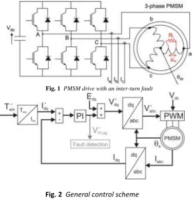
The system under study is depicted in Fig. 1. The drive is composed of a three-leg inverter and a three-phase PMSM. The DC-link voltage, the mechanical position and the three phase currents are measured. A turn-to-turn
fault is represented in the a-phase. The fault is characterized by the fault resistance and the ratio of shorted
turns compared to the number of series turns within one phase µSC. Both parameters are a priori unknown.
Regarding the healthy machine, the voltage equations expressed in the abc reference frame are given by:
(1)
with the abc voltages, the stator resistance, the inductance matrix, the abc phase
currents and the emf induced by the permanent magnets in the stator windings.
The models of the machine expressed in the stator and in the rotor reference frames are obtained by applying successively the Clarke and rotation transformations defined by:
6
(3)
with transformation matrices given by:
(4)
(5)
The quantity can be a vector of currents, voltages or fluxes and is the electrical position of the
rotor. The zero-sequence component is omitted as the machine is star-connected with isolated neutral point and ground fault is not considered. Applying the transformations (2) and (3) to the system (1) yields:
(6)
with
(7)
with the electrical pulsation, the magnitude of the fundamental component of the flux linkage due to
the permanent magnets and and the d- and q-axis inductances respectively.
2.2 Control parameters
The following control law with PI controllers and compensated emf is chosen (see Fig. 2):
(8)
where , are the transfer functions of the PI controllers, given by:
(9)
(10)
with s the Laplace variable and , , , the proportional and integral gains of the d- and q-axis
controllers.
If the bandwidth of the d-axis closed-loop transfer function is equal to , the pole-zero compensation
7
(11)
(12)
2.3 Model of machine with inter-turn fault
The modeling of PMSMs with a turn-to-turn fault is discussed in [40-42]. In [40], a simple electrical model is proposed, which shows that a turn-to-turn fault causes an unbalance of the drive. Further, the author shows that the fault decreases the fundamental value of the magnet flux linkage, i.e. its positive-sequence component, and therefore the positive-sequence emf as well. In [41], an analytical model of the fault in the rotor reference frame is proposed, whereas in [42] a finite-element analysis shows that the current in the shorted turns depends on the position of the turns in the slot as well.
Upon the fault occurrence, the change can be expressed as:
(13)
where are the dq-axis voltages upon the fault occurrence and are the changes due to the
fault. Because of the stator unbalance, the fault components can be expressed as a development with even
harmonics. Considering only the two first terms, can be expressed as:
(14)
The first term of (14) is associated with a change of positive-sequence voltage, while the second term is associated with a change of negative-sequence voltage.
Although the quantification of the change is given as a function of the fault parameters in [41], the fault is characterized by two unknown parameters and therefore the magnitude of the change gives an estimate of the fault severity only.
3. Fault detection scheme
3.1 Fortescue transformation for PMSM drives
The Fortescue transformation allows three-phase quantities to be split up into positive-, negative- and zero-sequence components. The conventional transformation is based on complex numbers (for quasi-steady-state operation at a given frequency), but an implementation in the time domain and stator reference frame is proposed in [25]. The authors show that:
(15)
(16)
The superscripts ‘+’ and ‘-’ denote the positive- and negative-sequence components respectively and is a phase-shift operator in the frequency domain which can be implemented in the time domain with adaptive filters. This structure allows a simplification of the implementation for variable-frequency
8
quantities as the use of a variable-length window is avoided. An instantaneous value of the symmetrical components is obtained without data storage and with a few calculations.
The scheme for the calculation of the symmetrical components is depicted in Fig. 3. The structure
requires the pulsation of the input quantities and . Regarding PMSM drives, the electrical pulsation is
directly available and no estimation is thus required. Each block “Filters” is composed of two filters with the following transfer functions:
(17)
(18)
where is a damping factor. The -filter is a band-pass filter, of which the filter gain is equal to 1 at the
electrical pulsation (i.e. at ) and allows filtering higher-order harmonic components. At the electrical
pulsation, the Q-filter has a unitary gain as well ( ), but it is a low-pass filter with output in
quadrature with the input. This filter is thus used for the implementation of .
3.2 Fault index
Considering grid-connected machines, the most common indices for turn-to-turn fault detection are the negative-sequence current or impedance. However, due to the closed-loop controller, the dq currents are likely to be close to their references, and as such unchanged upon the fault occurrence. In this case, the voltage at the machine terminals will be unbalanced. Therefore the fault index can be better derived from the negative- and positive-sequence component of the voltage references. At this step, a relevant fault index derived from (14) can be:
(19)
The fault index (19) is the ratio of negative- to positive-sequence voltages. The advantages of (19) are:
- the index is theoretically equal to zero in healthy operation;
- as decreases upon an intern-turn fault occurrence, the index takes benefit of an increase of
the numerator and a decrease of the denominator upon the fault occurrence, what increases the sensitivity to the fault.
However, as the magnitude of the positive sequence is much bigger than the one of the negative sequence, the change of the fault index can be low. Looking further at the compensations terms (7) and assuming the number of shorted turns is small, it can be noticed that:
- the dq currents will be close to their references;
- the mechanical speed will be unaffected upon the fault occurrence.
Consequently, the compensation terms are constant and insensitive to the fault. To increase the sensitivity to the fault, the calculation of the negative- and positive-voltages is then applied to the output of the PI
controllers, as depicted in Fig. 2. Hence, considering that upon the fault occurrence and
9
(20)
For implementation purpose, the proposed fault index is obtained as follows:
1. Apply the inverse rotation matrix to the dq voltage outputs of the PI controllers
(Fig. 2).
2. Calculate the negative- and positive-sequences of according to the scheme of Fig. 3.
3. Calculate the ratio between the magnitudes of the negative- and positive-sequence components:
(21)
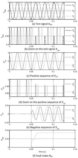
Fig. 4 shows simulation results obtained with the proposed scheme and a simple signal analysis. Initially, the three-phase signals are perfectly balanced, as shown in Fig. 4(a) and (b). Consequently, the signal has only a positive-sequence (Fig. 4(c) and (d)). At time t=0.05s, an unbalance of 0.05pu appears on the a-phase. Next, the magnitude of the positive sequence slightly drops to 0.983, while the magnitude of the negative sequence rises to 0.0167 (Fig. 4(e)). The ratio of both amplitudes is equal to the fault index
(Fig. 4(f)).
The response of the fault index is related to the dynamics of the adaptive filters, which depends on the
damping factor and the pulsation . Simulations show that is a good tradeoff between the rejection
of higher-order harmonics and the dynamics of the filters. Several simulation results are presented in Fig. 5 and Fig. 6, which show the value of the fault index under non-stationary conditions.
Fig. 5 shows the response of the fault index when starting the motor. Three speed ramps with different slopes have been simulated. The accelerations are 500, 1000 and 2000rpm per second on a time horizon of two seconds. The amplitude of the three abc signals is kept constant in these simulations. It can be observed in Fig. 5 that the value of the fault index is initially equal to one and decreases quickly to zero. The initial value is due to the filter dynamics as both sequences have a null magnitude at the beginning. Next, the convergence speed increases with the pulsation. These simulations show that the convergence speed is poor at low speed and the fault detection should be inhibited below a minimum speed.
Fig. 6 shows the response of the fault index in case of load changes at constant speed. The amplitude of the three-phase signals is initially equal to one and the final value is equal to two. The three plots show the response in case of step, first-order (FO)-like response with time constant equal to 0.01s and ramp with slope equal to 10. It can be seen that the index takes large values for the step and for the FO-like responses but the transient vanishes quickly. Obviously, this cannot be ignored as threshold-based fault detection will fail with this method. An additional low-pass filtering is a possible solution, but in the proposed solution the decision system will handle it. The latter is described in the following section. Its role consists of tracking changes of the fault index but also to verify that the changes are permanent, i.e. due to a fault.
3.3 Decision system
The decision system has to decide whether there is a fault or not. The CUSUM algorithm has been used for this purpose. A theoretical background of this algorithm can be found in [26]. In brief, this algorithm processes the
10
It is assumed that the successive discrete values of the fault index are distributed according to a
Gaussian probability law with mean and variance before the fault occurrence and a mean and
same variance following the fault occurrence. Fig. 7 shows the probability density functions associated with
these distributions. The probability density functions associated to the healthy state is given by:
(22)
Fig. 7 illustrates the confidence level to associate with each value of the fault index. As the
distributions are symmetrical, the healthy state is more likely at time k in case and
conversely in case .
The CUSUM algorithm is based on the log-likelihood ratio (LLR) calculated at each sample k. The LLR is given by:
(23)
where and are the probability density function of the faulty and healthy distributions respectively.
From (22) and (23), it follows (see Appendix II):
(24)
The LLR at time k is therefore positive if and negative if . Hence, if the
mean of is equal to (faulty condition), the successive values , ,… are generally
positive, whereas these values are generally negative in case the mean of is equal to (healthy
condition). Therefore, an appropriate decision function g is given by:
(25)
This decision function is close to zero as long as there is no fault and starts increasing upon the fault occurrence. A decision that the faulty situation holds can be made in case crosses a user-chosen threshold which affects the fault detection delay . A possible re-initialization of the CUSUM function allows observing the persistence of the fault.
3.4 Practical implementation of the fault detection scheme
The following observations have to be taken into account for the practical implementation of the fault detection scheme:
11
- the mean value of the fault index in healthy condition ( is close to zero, but is not exactly zero. The
residual value depends on the operating conditions and must be taken into account for the detection of small-magnitude changes;
- the mean value of the fault index in case of turn-to-turn fault ( ) depends on the fault parameters
µSC and , which are both unknown;
- the calculation of the symmetrical components is impossible at standstill and is imprecise at low speed;
- the fault index is sensitive to abrupt changes of the operating point.
To overcome these problems, the following implementation is proposed:
- a recording of the values of the fault index in healthy operation is performed (ideally at the drive commissioning and in real operating conditions), as already proposed in [1], [8], [18] and [21];
- a minimum fault magnitude is selected;
- the fault detection is inhibited at zero and low speed;
- the threshold is chosen by also taking into account the drive operating conditions.
Regarding the CUSUM algorithm, the values of are stored in a 2-dimensional lookup table with speed and
torque (or equivalently the torque reference) as inputs (see Fig. 8). The value of is such that:
(26)
Further, the term in (24) is a constant gain which can be accounted for in the detection threshold .
That is, the variance can be unknown and the LLR can be reformulated as follows:
(27)
Hence, the number of samples M required for reaching the detection threshold from the sample index i of
the fault occurrence is such that:
(28) Given a sampling period and assuming is constant for a given fault, the detection delay is given by:
(29)
The detection delay is thus proportional to the detection threshold and the sampling period and inversely proportional to the magnitude of the fault index.
3.5 Computational cost
An advantage of the proposed method is the low computational cost. Besides the control tasks, here is a summary of the operations required for fault detection.
12
Starting from the output of the PI controllers, the operations are: - inverse rotation: 4 multiplications and 2 sums;
- adaptive filters (17) and (18) (x2): 2 multiplications, 5 multiplications by a constant, 4 sums and 2 delays;
- positive- and negative-sequences (15) and (16): 8 sums and 4 multiplications by a constant; - index calculation: 4 multiplications, 2 sums, 1 square root and 1 division;
- CUSUM algorithm: 4 sums, 2 delays, 3 comparisons, 2 multiplications by a constant and 1 memory access;
- additional logic for enabled execution of blocks.
4. Experimental results
4.1 Test-bed description
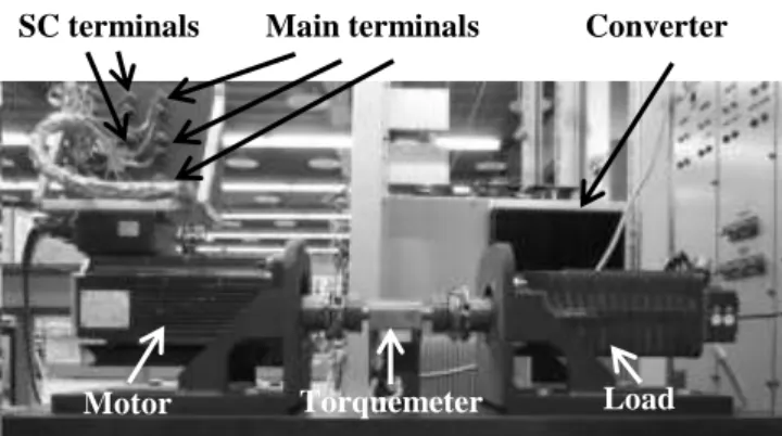
The test bed used for the experimentation is shown in Fig. 9. The setup is composed of two PMSMs, a
torquemeter, a three-leg inverter and a dSPACE 1006 board. The load machine is connected to a three-phase resistance network and the load torque is thus proportional to the speed. The position sensor is a resolver mounted on the shaft of the motor. Three current sensors LEM LA55-P are available in an external box. The DC-link voltage sensor is integrated within the converter.
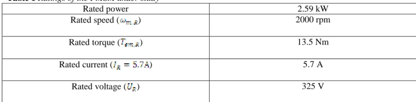
Table 1 Ratings of the PMSM under study
Rated power 2.59 kW
Rated speed ( ) 2000 rpm
Rated torque ( ) 13.5 Nm
Rated current ( ) 5.7 A
Rated voltage ( ) 325 V
Table 2 Winding parameters of PMSM
Winding parameter Value
Number of parallel wires 4
Wire diameter 2x0.56 + 2x0.60 mm²
Number of slots 36
Number of series turns per
coil 30
Number of coils per phase (series configuration)
6 Resistance of one phase at
T=20°C 1.39Ω
dq-axis inductances 11.4mH
Number of pole pairs
13
The machine under study is a three-phase PMSM which has been rewound (see Fig. 10) to access the 6 main power terminals and to integrate additional turns for testing the fault detection scheme. The ratings of the machine are given in Table 1.
The winding parameters are given in Table 2, whereas the winding pattern is shown in Fig. 11 (single-layer integral-slot concentrated winding). The input (output) terminals of phase x is denoted by Ix (Ox),
.
Additional turns have been added for generating inter-turn short-circuit faults. Two turns are located in slots 1 and 6, two in slots 13 and 18 and two in slots 25 and 30. Their copper section is approximately equal to the sum of the sections of the parallel wires, i.e. . These additional turns are all inserted in slots belonging to the a-phase. Therefore, by adding one or two turns in series with each phase, only the zero-sequence component of the emf is affected, what does not affect the asymmetry of the machine (no effect on the positive and negative voltage of the original winding). These turns can be individually shorted at the terminals of the machine via external cables or resistances. These cables increase the resistance of the turns, what can be considered as the fault resistance . An external potentiometer was always used during early tests, but a verification has shown that a short-circuit fault at the terminals may be performed without excessive heating for a duration of approximately 30s.
4.2 Parameters of the fault-detection scheme
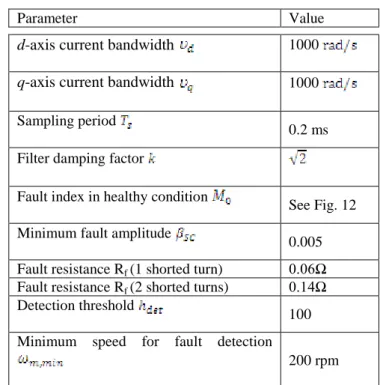
The parameters of the controllers and of the fault-detection scheme that have been used for the tests are given in Table 3.
Table 3 Parameters of fault detection scheme
Parameter Value
d-axis current bandwidth 1000
q-axis current bandwidth 1000
Sampling period
0.2 ms Filter damping factor
Fault index in healthy condition
See Fig. 12 Minimum fault amplitude
0.005
Fault resistance Rf (1 shorted turn) 0.06Ω
Fault resistance Rf (2 shorted turns) 0.14Ω
Detection threshold
100 Minimum speed for fault detection
200 rpm
The sampling time is equal to 0.2ms. The control loops and fault detection work within the same control platform at the same frequency (5kHz). As the discretization of the adaptive filters (17) and (18) influences the value of the fault index, a minimum ratio of 50 between the sampling frequency and the electrical frequency has to be kept.
The value of the fault index in healthy condition is depicted in Fig. 12, which shows the mapping of the fault index as a function of the electromagnetic torque for several mechanical speeds. This
14
mapping has been obtained by operating the machine at various speeds and loads in steady state. There are actually about 40 different operating points that have been considered. For each point, the value of are equal to the average value of a data window of 4s. Combined with an interpolation between the various points,
this proved to be enough for a good precision. Generally, the values decrease with larger electromagnetic
torques and increase for larger speeds. Tests have been conducted over a period of time longer than six months. The index has been stable within this period and a good reproducibility has been observed.
The minimum fault amplitude is chosen equal to 0.005. This value can be decreased but an
additional procedure to freeze the fault detection in transient operation should then be added to avoid false alarms (see following sections).
The fault resistance is somewhat high since its value is several times larger than the turn resistance
(approximately equal to ). As a result, the short-circuit current is relatively low
(approximately equal to ), but the value of the fault index is lower as well in case of fault.
The value of the detection threshold will be discussed in the following sections.
Fault detection is inhibited below 200rpm, mainly due to a high cogging torque and low inertia of the test bed. The calculated positive and negative- voltages were not accurate below this threshold and fault detection was not effective (fault could not be distinguished from noise). As voltages which induce the short-circuit currents are associated with the electromotive forces, they are proportional to the speed. It is then normal that the effect is less detectable at low speed since the short-circuit currents amplitudes are lower than at high speed. It is also less important to detect a fault when its impact on the ageing of the machine is lower. Of course, if it is wanted to detect short-circuit from zero speed, a complementary technic is necessary. For the prototype, RMS currents in one and two turns short-circuited have been measured in the range 0 to 400 rpm at different loads. The results confirm a linear dependence with the speed with a maximum value of 0.43 pu for the short-circuit current at 400 rpm.
4.3 Turn-to-turn detection in steady-state operation
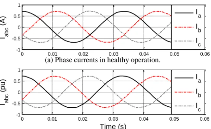
Experimental results of the whole scheme are presented in Fig. 14, Fig. 14 and Fig. 15. The test is performed in
steady state with and .
Fig. 14 compares the sampled phase currents in healthy and faulty conditions. Because of the closed-loop control, no difference is observed. This is confirmed in Fig. 14, which presents experimental results of a short-circuit fault occurring at time t=2.85s until t=17s (2 turns out of 182). Fig. 14(a) and (b) show the dq currents and measured electromagnetic torque respectively, both being unaffected by the fault. The fault index is shown in Fig. 14(c), while the CUSUM function is shown in Fig. 14(d). For the operating conditions under study,
the corresponding value of the fault index in healthy operation is equal to 0.019, as it can be seen in Fig. 12
and Fig. 14(d). Upon the fault occurrence, the fault index rises to approximately 0.03 and the CUSUM function
starts increasing. The decision function crosses the detection threshold at time . The CUSUM function
is then re-initialized. For this test, the fault disappears at time and the CUSUM function returns to zero.
Regarding the detection delay, the value predicted by (29) gives , which coincides with
15
Additional details are given in Fig. 15(a), (b) and (c), which show the voltage references expressed in the rotor reference frame, the PI controller output positive-sequence magnitude and the PI controller-output negative-sequence magnitude respectively. A zoom on the fault occurrence at t=2.85s is presented. The value
of drops of about 1V upon the fault occurrence and the voltage ripple increases. This is better explained in
Fig. 15(b) and (c), where the voltage drop is seen as a decrease of the positive-sequence magnitude and the voltage ripple as an increase of the negative-sequence magnitude. The difference as regards to the sensitivity when using the PI controller output instead of the voltage reference is also evidenced: the decrease of the positive-sequence magnitude is approximately equal to 1/85 for the voltage references, while the decrease is approximately equal to 1/20 for the PI controller output.
In case only one turn is shorted with a fault resistance Rf equal to 0.06Ω, the change of the fault index
is about 0.002 for the same operating conditions, as shown in Fig. 16. Although it is possible to detect a change of such a low magnitude, i.e. by setting to 0.001, the detection becomes very sensitive to transient operation (see following section).
It has to be noted that the index was observed to be insensitive at no load for faults with one and two shorted turns.
4.4 Behavior of the fault-detection method in transient operation (without fault)
Fig. 17 shows the response of the fault-detection method in case of transient operation (speed and load ramps) without fault. The machine is first at standstill and is approximately equal to 0.07. The speed starts
increasing at time , as shown in Fig. 17(a). The load torque is proportional to the mechanical speed as it
can be seen in Fig. 17(b). The fault detection is enabled when the speed crosses 200rpm and and
become quickly close. When the speed starts decreasing at time , the transient operation causes a
transient of the fault index which becomes temporally larger than its steady-state value (Fig. 17(c)), similarly to the simulation results of Fig. 6. The CUSUM function starts increasing, but the fault index is restored before the decision function crosses the threshold (Fig. 17(d)).
Obviously, under non-stationary conditions, the value of the decision threshold is not only
dependent of the detection delay, but has to be chosen in a way that false alarms due to dynamic conditions are avoided. This can be investigated at early stages by testing a mission profile in simulation.
At the drive commissioning, a further verification has to be performed to ensure that this threshold is never crossed during the healthy operation.
In case of torque-controlled drives with very high dynamics, the value of the fault index can become high during transient operation and this would lead to unreasonably high thresholds. In that case, a pragmatic solution consists in activating the fault detection only when sufficient steady state is observed, for example, in case the compensation terms (7) are close to the voltage references (8).
4.5 Behavior of the fault detection method in transient operation (with fault)
Fig. 18 shows the response of the fault detection method in case of transient operation and two shorted turns. It can be observed that the fault index is greater than in healthy operation all along the test. It can also be noticed that the short periods in which the fault detection is inhibited (near zero speed) do not cause a significant change of the detection delay.
16
5. Conclusions
A complete method for fault detection of inter-turn faults in PMSM drives has been presented and experimentally validated. The main advantages of the method are: the simple implementation, a low computational cost which allows the fault detection to be embedded on the control platform at no cost and a good sensitivity thanks to an access to the PI controller outputs.
Although the implementation of the proposed fault index in the time domain makes it sensitive to non-stationary conditions, the association with the CUSUM algorithm allows mitigating this drawback to some extent. Hence, the method can be applied to various industrial applications such as fans or pumps, but also to applications such as wind turbines and electric vehicles.
Various objectives can be achieved by considering the decision of the monitoring system. For example, this gives a condition for inspection, maintenance or replacement of the electric machine, or also a criterion to initiate a reconfiguration of the drive, assuming the drive is fault-tolerant.
For future works, the authors suggest to combine this fault-detection method with other techniques for monitoring mechanical, inverter and sensor faults. Investigations of complementary techniques based on signal injection seem also promising for extending fault detection at zero and in the low-speed region.
6. Appendix I
The system equations are given by:
(A.1)
That is:
(A.2)
The control law is such that:
(A.3)
Applying the voltage references (A.3) to the system (A.2) yield: )
(A.4)
In steady state, the derivative terms are equal to zero. Hence:
(A.5)
In the rotor reference frame, the constant terms are associated with the positive sequence, while the terms
17
(A.6)
7. Appendix II
The log-likelihood ratio is calculated as follows:
8. Acknowledgments
The authors would like to thank the Belgian F.R.I.A. for the funding of this research project.
9. References
[1] Kliman G., Premerlani W., Koegl R., and Hoeweler D.: ‘A New Approach to On-Line Turn Fault Detection in AC Motors’. In IEEE Industry Applications Conference, 1996
[2] Nandi S., Toliyat H.A., and Li X.: ‘Condition monitoring and fault diagnosis of electrical motors-a review’, IEEE Transactions on Energy Conversion, 2005, 20, (4), pp. 719–729
[3] Tallam R.M., Lee S., Stone G., Kliman G., Yoo J., Habetler T. G., and Harley R.: ‘A survey of methods for detection of stator-related faults in induction machines’, IEEE Transactions on Industry Applications, 2007, 43, (4), pp. 920–933
[4] IEC Technical Specification 60034-18-1: ‘Qualification and type tests for Type I electrical insulation systems used in rotating electrical machines fed from voltage converters’, 2006
[5] Tavner, P.J.: ‘Review of condition monitoring of rotating electrical machines’, IET Electric Power Applications, 2008, 2, (4), pp. 215-247
[6] Bellini A., Filippetti F., Tassoni C., and Capolino G.-A.: ‘Advances in diagnostic techniques for induction machines’, IEEE Transactions on Industrial Electronics, 2008, 55, (12), pp. 4109–4126
[7] Grubic S., Aller J.M., Lu B., and Habetler T.G.: ‘A survey on testing and monitoring methods for stator insulation systems of low-voltage induction machines focusing on turn insulation problems’, IEEE Transactions on Industrial Electronics, 2008, 55, (12), pp. 4127–4136
[8] Joksimovic G.M., and Penman J.: ‘The detection of inter-turn short circuits in the stator windings of operating motors’, IEEE Transactions on Industrial Electronics, 2000, 47, (5), pp. 1078-1084
[9] Benbouzid M.E.H.: ‘A review of induction motors signature analysis as a medium for faults detection’, IEEE Transactions on Industrial Electronics, 2000, 47, (5), pp. 984–993
[10] Kim, H.: ‘On-line mechanical unbalance estimation for permanent magnet synchronous machine drives’, IET Electric Power Applications, 2009, 3, (3), pp. 178-186
[11] Akin B., Orguner U., and Toliyat H.A.: ‘Low order PWM inverter harmonics contributions to the inverter-fed induction machine fault diagnosis’, IEEE Transactions on Industrial Electronics, 2008, 55, (2), pp. 610-619
[12] Kyeong-Hwa Kim: ‘Simple Online Fault Detecting Scheme for Short-Circuited Turn in a PMSM Through Current Harmonic Monitoring’, IEEE Transactions on Industrial Electronics, 2011, 58, (6), pp.2565-2568
18
[13] Bellini A., Yazidi A., Filippetti F., Rossi C., and Capolino G.-A.: ‘High frequency resolution techniques for rotor fault detection of induction machines’, IEEE Transactions on Industrial Electronics, 2008, 55, (12), pp. 4200-4209
[14] Rajagopalan S., Restrepo J., and Aller J.: ‘Nonstationary Motor Fault Detection Using Recent Quadratic Time – Frequency Representations’, IEEE Transactions on Industry Applications, 2008, 44, 3, pp. 735-744 [15] Rosero J., Romeral L., and Ortega J.: ‘Short-circuit detection by means of empirical mode decomposition
and Wigner – Ville distribution for PMSM running under dynamic condition’, IEEE Transactions on Industrial Electronics, 2009, 56, (11), pp. 4534-4547
[16] Gritli Y., Stefani A., Rossi C., Filippetti F., and Chatti A.: ‘Experimental validation of doubly fed induction machine electrical faults diagnosis under time-varying conditions’, Elsevier Electric Power Systems Research, 2011, 81, (3), , pp. 751-766
[17] Casadei D., Filippetti F., Rossi C., and Stefani A.: ‘Magnets faults characterization for Permanent Magnet Synchronous Motors’. Proc. IEEE International Symposium on Diagnostics for Electric Machines, Power Electronics and Drives, September 2009, pp.1-6
[18] Tallam R.M., Habetler T.G., and Harley R.G.: ‘Stator winding turn-fault detection for closed-loop induction motor drives’, IEEE Transactions on Industry Applications, 2003, 39, (3), pp. 720- 724
[19] Lee Y. and Habetler T.G.: ‘An on-line stator turn fault detection method for interior pm synchronous motor drives’. Proc. IEEE Applied Power Electronics Conference, March 2007, pp. 825-831
[20] Stefani A., Yazidi A., Rossi C., Filippetti F., Casadei D., and Capolino G.-A.: ‘Doubly Fed Induction Machines Diagnosis Based on Signature Analysis of Rotor Modulating Signals’, IEEE Transactions on Industry Applications, 2008, 44, (6), pp.1711-1721
[21] Trutt F., Sottile J., and Kohler J.: ‘Online condition monitoring of induction motors’, IEEE Transactions on Industry Applications, 2002, 38, (6), pp. 1627-1632
[22] Crabtree C.J., Djurovi S., Tavner P.J., and Smith A.C.: ‘Fault frequency tracking during transient operation of wind turbine generators’. Proc. International Conference on Electrical Machines (ICEM), September 2010, pp.1-5
[23] Hong J., Lee S.B., Kral C., and Haumer A.: ‘Detection of airgap eccentricity for permanent magnet synchronous motors based on the d-axis inductance’. Proc. IEEE International Symposium on Diagnostics for Electric Machines, Power Electronics & Drives, September 2011, pp. 378-384
[24] Khov M., Regnier J., and Faucher J.: ‘Monitoring of turn short-circuit faults in stator of PMSM in closed loop by on-line parameter estimation’. Proc. IEEE International Symposium on Diagnostics for Electric Machines, Power Electronics and Drives, September 2009, pp. 1-6
[25] Rodr gue P., Luna A., Candela I., Mujal R., Teodorescu R., and Blaabjerg F.: ‘Multiresonant Frequency-Locked Loop for Grid Synchronization of Power Converters Under Distorted Grid Conditions’, IEEE Transactions on Industrial Electronics, 2011, 58, (1), pp.127-138
[26] Blanke M., Kinnaert M., Lunze J., and Staroswiecki M.: ‘Fault diagnosis of continuous-variable systems’, in ‘Diagnosis and fault-tolerant control’, Springer, 2006, 2nd edition, pp. 189-298
[27] Meinguet F. and Gyselinck J.: ‘Fault Detection, Isolation and Reconfiguration of Three-Phase AC Drive with Current Sensor Fault’. Proc. IEEE International Electric Machines and Drives Conference, May 2011, pp. 200-205
[28] Gálvez-Carrillo M., and Kinnaert M.: ‘Sensor fault detection and isolation in three-phase systems using a signal-based approach’, IET Control Theory & Applications, 2010, 4, (9), pp. 1838-1848
[29] Meinguet F., Semail E., and Gyselinck J.: ‘An on-line method for stator fault detection in multi-phase PMSM drives’, Proc. IEEE Vehicle Power and Propulsion Conference, September 2010, pp. 1–6
[30] Meinguet F., Kestelyn X., Semail E., and Gyselinck J.: ‘Fault Detection, Isolation and Control Reconfiguration of Three-Phase PMSM Drives’. Proc. IEEE International Symposium on Industrial Electronics, 2011, pp. 2091-2096
[31] Bennett J.W., Mecrow B.C., Atkinson D.J., and Atkinson G.J.: ‘Safety-critical design of electromechanical actuation systems in commercial aircraft’, IET Electric Power Applications, 2011, 5, (1), pp. 37-47
[32] Pang Y., Zhu Z.Q., Chen X.J., and Channon S.: ‘Design concept of short-circuit fault-tolerance permanent magnet machine’. Proc. IET International Conference on Power Electronics, Machines and Drives, 2010, pp. 1-4
[33] Arumugam P., Hamiti T., and Gerada C.: ‘Modeling of Different Winding Configurations for Fault-Tolerant Permanent Magnet Machines to Restrain Interturn Short-Circuit Current’, IEEE Transactions on Energy Conversion, 2012, 27, (2), pp.351-361
[34] Barcaro M., Bianchi N., and Magnussen F.: ‘Faulty Operations of a PM Fractional Slot Machine with a Dual Three Phase Winding’, IEEE Transactions on Industrial Electronics, 2011, 58, (9), pp. 3825-3832 [35] Alberti L., and Bianchi N.: ‘Experimental Tests of Dual Three-Phase Induction Motor Under Faulty
19
[36] Ruba M., and Szabó L.: ‘Fault tolerant electrical machines. State of the Art and future directions’, Journal of Computer Science and Control Systems, 2008, 1, (1), pp. 202-207
[37] El-Refaie A.M.: ‘Fault-tolerant permanent magnet machines: A review’, IET Electric Power Applications, 2011, 5, (1), pp. 59-74
[38] Klontz K.W., Miller T.J.E., McGilp M.I., Karmaker, H., and Zhong, P.: ‘Short-Circuit Analysis of Permanent-Magnet Generators’, IEEE Transactions on Industry Applications, 2011, 47, (4), pp.1670-1680 [39] Harnefors L., Pietilainen K.., and Gertmar, L.: ‘Torque-maximizing field-weakening control: design,
analysis, and parameter selection’, IEEE Transactions on Industrial Electronics, 2001, 48, (1), pp.161-168 [40] Lee Y.: ‘A stator turn fault detection method and a fault-tolerant operating strategy for interior PM
synchronous motor drives in safety-critical applications’. PhD thesis, Georgia Institute of Technology, 2007 [41] Romeral L., Urresty J.C., Riba Ruiz J.-R., and Garcia Espinosa A.: ‘Modeling of Surface-Mounted
Permanent Magnet Synchronous Motors With Stator Winding Interturn Faults’, IEEE Transactions on Industrial Electronics, 2011, 58, (5), pp.1576-1585
[42] Sun Z., Wang J., and Howe D.: ‘Analytical prediction of the short-circuit current in fault-tolerant permanent-magnet machines’, IEEE Transactions on Industrial Electronics, 2008, 55, (12), pp. 4210-4217
Fig. 1 PMSM drive with an inter-turn fault
Fig. 2 General control scheme
20
Fig. 4 Simulation results for an unbalance of 0.05 occurring on phase a at time t=0.05s with =300 rad s-1
0 0.05 0.1 0.15 -0.02 0 0.02 Time (s) X -X -X -0 0.05 0.1 0.15 -1 0 1 Time (s) Xabc Xa Xb Xc 0 0.05 0.1 0.15 -1 0 1 Time (s) X + X+ X+ (f) Fault index RNP (c) Positive sequence of X
(a) Test signal Xabc
0 0.05 0.1 0.15 0 0.01 0.02 Time (s) RNP
(e) Negative sequence of X
0 0.05 0.1 0.15 0.9 0.95 1 Time (s) Xabc Xa Xb Xc
(b) Zoom on the test signal Xabc
0 0.05 0.1 0.15 0.96 0.98 1 Time (s) X + X+ X+
21
Fig. 5 Simulation of the fault detection scheme under healthy and non-stationary conditions: speed ramp from
standstill with different accelerations (balanced three-phase signals with constant peak values and three pole-pairs)
Fig. 6 Simulation of the fault detection scheme under healthy and non-stationary conditions: load changes from
1pu to 2pu at constant pulsation =300 rad s-1 and with different dynamics (step, first-order-like response with time constant equal to 0.01s and ramp with slope equal to 10)
Fig. 7 Probability density functions of the fault index under healthy and fault conditions.
Fig. 8 Implementation of the CUSUM algorithm for turn-to-turn short-circuit fault detection
-0.20 -0.1 0 0.1 0.2 0.3 0.4 5 10 FI values[pu] FI p d f p0(RNP) pSC(RNP) MSC M0 0 0.05 0.1 0.15 0.2 0.25 0.3 0.35 0.4 0 0.1 0.2 Time (s) R NP Step FO Ramp 0 0.2 0.4 0.6 0.8 1 1.2 1.4 1.6 1.8 2 0 0.5 1 Time (s) RNP 500rpm/s 1000rpm/s 2000rpm/s
(a) Fault index RNP
(b) Zoom on fault index RNP
0 0.2 0.4 0.6 0.8 1 1.2 1.4 1.6 1.8 2 0 0.01 0.02 Time (s) RNP 500rpm/s 1000rpm/s 2000rpm/s
22
Fig. 9 Test bed used for the experimentation
Fig. 10 Stator of rewound PMSM with additional turns (only one can be seen in the figure)
Fig. 11. Winding pattern of PMSM Main terminals
Terminals
Converter
Motor Torquemeter Load
SC terminals Terminals
23 0 0.1 0.2 0.3 0.4 0.5 0.6 0.7 0.8 0.9 1 0 0.005 0.01 0.015 0.02 0.025 0.03 0.035 0.04 0.045 0.05 Tem (pu) R NP m=200RPM m=400RPM m=600RPM m=800RPM m=1200RPM m=1400RPM 200RPM 400RPM 800RPM 1400RPM 1200RPM 600RPM
Fig. 12 Mapping of the residual value of the fault index in healthy operation as a function of the operating conditions
Fig. 13 Experimental results showing the sampled phase currents in healthy and faulty conditions. 0 0.01 0.02 0.03 0.04 0.05 0.06 -1 -0.5 0 0.5 1 Time (s) I abc ( A ) Ia Ib Ic 0 0.01 0.02 0.03 0.04 0.05 0.06 -1 -0.5 0 0.5 1 Time (s) I abc ( p u ) Ia Ib Ic
(a) Phase currents in healthy operation.
24
Fig. 14 Experimental results of the fault-detection scheme in steady state with 2 shorted turns out of 182 and
Rf = 0.14Ω. Fault occurs at time t=2.85s and disappears at t=17s
0 2 4 6 8 10 12 14 16 18 20 0 20 40 60 80 100 120 Time (s) g ( C U S U M f u n c ti o n ) g hdet
(c) Fault index and its reference for the operating conditions.
(d) CUSUM function. 0 2 4 6 8 10 12 14 16 18 20 0 0.5 1 Time (s) T em ( p u ) 0 2 4 6 8 10 12 14 16 18 20 -0.5 0 0.5 1 Time (s) Idq ( p u ) Id I q
(a) Currents expressed in the rotor reference frame.
(b) Measured electromagnetic torque.
0 2 4 6 8 10 12 14 16 18 20 0.01 0.015 0.02 0.025 0.03 0.035 0.04 Time (s) F a u lt i n d e x a n d r e fe re n c e M0 R NP
25
Fig. 15 Experimental results showing the effects of a short-circuit fault (2 turns out of 182 and Rf = 0.14Ω) on the voltage references. Fault occurs at time t=2.85s
0 2 4 6 8 10 12 14 16 18 20 0.015 0.02 0.025 0.03 0.035 0.04 Time (s) F a u lt i n d e x a n d r e fe re n c e R ID 0
Fig. 16 Experimental results of the fault-detection scheme in steady state with 1 shorted turn out of 181 and
Rf = 0.06Ω. Fault occurs at time t=3s
(a) Voltage references expressed in the rotor reference frame.
(b) Magnitude of the voltage positive-sequence (output of the PI controller). 0 0.5 1 1.5 2 2.5 3 3.5 4 4.5 5 -20 0 20 40 60 80 100 Time (s) Vdq ( V ) V d V q 2.6 2.7 2.8 2.9 3 3.1 82 83 84 85 86 2.6 2.7 2.8 2.9 3 3.1 -26 -24 -22 -20 -18 -16 0 0.5 1 1.5 2 2.5 3 3.5 4 4.5 5 0 0.2 0.4 0.6 0.8 1 Time (s) |V PI , -| (V ) 0 0.5 1 1.5 2 2.5 3 3.5 4 4.5 5 17 18 19 20 21 Time (s) |V PI , + | (V ) (c)
(c) Magnitude of the voltage negative-sequence (output of the PI controller).
26
Fig. 17 Experimental results of the fault detection scheme in case of transient operation (speed and load ramps)
and healthy operation
0 0.5 1 1.5 2 2.5 3 3.5 4 4.5 5 -1000 -500 0 500 1000 Time (s) m ( rp m ) m m,ref 0 0.5 1 1.5 2 2.5 3 3.5 4 4.5 5 -0.8 -0.6 -0.4 -0.2 0 0.2 0.4 0.6 Time (s) T em ( p u ) 0 0.5 1 1.5 2 2.5 3 3.5 4 4.5 5 -0.02 0 0.02 0.04 0.06 0.08 0.1 Time (s) F a u lt i n d e x a n d r e fe re n c e R NP 0 0 0.5 1 1.5 2 2.5 3 3.5 4 4.5 5 0 20 40 60 80 100 120 Time (s) g ( C U S U M f u n c ti o n ) g h det
(a) Mechanical speed.
(b) Load torque.
(c) Fault index and its reference for the operating conditions.
27
Fig. 18 Experimental results of the fault detection scheme in case of transient operation (random speed profile) with 2 shorted turns
0 2 4 6 8 10 12 14 16 18 20 0 20 40 60 80 100 120 Time (s) g ( C U S U M f u n c ti o n ) g h det 0 2 4 6 8 10 12 14 16 18 20 -1000 -500 0 500 1000 Time (s) m ( rp m ) 0 2 4 6 8 10 12 14 16 18 20 -1 -0.5 0 0.5 1 Time (s) T em ( p u ) 0 2 4 6 8 10 12 14 16 18 20 -0.05 0 0.05 0.1 0.15 0.2 Time (s) F a u lt i n d e x a n d r e fe re n c e R NP 0 (d) CUSUM function. (a) Mechanical speed.
(b) Load torque.