Science Arts & Métiers (SAM)
is an open access repository that collects the work of Arts et Métiers Institute of
Technology researchers and makes it freely available over the web where possible.
This is an author-deposited version published in: https://sam.ensam.eu
Handle ID: .http://hdl.handle.net/10985/6995
To cite this version :
Joao Paulo NOBRE, J.-H. STIFFEL, A. NAU, José OUTEIRO, Antonio BATISTA, W. VAN
PAEPEGEM, B. SCHOLTES Induced drilling strains in glass fibre reinforced epoxy composites
-CIRP Annals Manufacturing Technology p.1-4 - 2013
Any correspondence concerning this service should be sent to the repository
Administrator : [email protected]
Induced drilling strains in glass fibre reinforced epoxy composites
J.P. Nobre
a,b, J.-H. Stiffel
c, A. Nau
c, J.C. Outeiro (2)
d, A.C. Batista
a, W. Van Paepegem
e, B. Scholtes
caCEMDRX, Department of Physics, University of Coimbra, PT-3030-728 Coimbra, Portugal bDepartment of Mechanical Engineering, University of Coimbra, PT-3030-728 Coimbra, Portugal cIfW, Institute of Materials Engineering, Kassel University, D-34109 Kassel, Germany
dLaBoMaP, Arts et Métiers ParisTech – CER de Cluny, F-71250 Cluny, France
eDepartment of Materials Science and Engineering, Ghent University, B- 9052 Zwijnaarde, Belgium
Residual strains induced by drilling of glass-fibre reinforced polymers (GFRP) were determined using a hybrid experimental-numerical methodology. Experimentally, a set of GFRP specimens were drilled under well-defined tensile (calibration) stresses, using an especially designed tensile test device. To remove the effect of the initial residual stresses, this methodology considers differential stress values instead of absolute ones. Numerically, the experimental procedure was simulated using the finite element method. The induced drilling strains were determined by comparing the experimental measured strains with those calculated numerically. Clear differences between the selected drilling operations could be observed and evaluated. Drilling, Composite, Residual stress
1. Introduction
The improvement of the drilling process of fibre-reinforced polymers (FRPs) is important for reducing the manufacturing costs, but also for improving the part quality. Delamination phenomenon and high tensile residual stresses should be avoided, owing to their well-known negative effect on mechanical behaviour. Residual stresses can have a great influence on functional performance and life of the machined component or structure [1]. The thermo-mechanical phenomena developed during the drilling process of FRPs can induce tensile residual stresses, which together with the initial residual stresses due to the curing process [2], can affect the quality of the drilled hole [3, 4]. Moreover, the residual stresses cannot be relieved by using thermal relaxation due to the mismatch of the thermal expansion coefficients of fibres and matrix and the temperature damage to the polymer matrix. In addition, the incremental hole-drilling technique (IHD) seems to be a promising technique for measuring in-depth non-uniform residual stresses in FRPs [5, 6]. However, knowledge of drilling stresses is also crucial for the accuracy of this technique [7]. In both contexts, the knowledge of the induced drilling strain is important for drilling process improvement. In this study a methodology to determine the induced drilling strains is proposed and applied to a glass-epoxy composite. Preliminary results in carbon-epoxy composites were presented in [8]. The objective is to optimize the drilling process, not only to improve the quality of manufacturing, but also to improve the applicability of the IHD technique.
2. The hybrid experimental-numerical methodology (HENM)
The HENM methodology aims to quantify the effect of the drilling process on the material by determining the induced drilling strain and related residual stress. It is based on the comparison between the strain relaxation field, measured during incremental drilling of a specimen subjected to a well-known applied tensile stress, and the strain relaxation field calculated by hole-drilling simulation on a semi-infinite plate subjected to the same stress and geometrical parameters, using the finite element method (FEM). More
precisely, during incremental drilling on a tensioned specimen, a set of curves of strain relaxation as a function of the depth is obtained. A set of ideal curves is further obtained by hole-drilling simulation using FEM. The direct comparison between both curves allows the induced drilling strains to be determined. However, the relieved strain due to an initial residual stress field, prior to hole-drilling, must be separated from that corresponding to the applied calibration stress. An accurate separation of the source of the strain relaxation measured during drilling is, therefore, crucial. To accomplish this requirement a procedure similar to one used by Rendler [9] was conceived. Based on the superposition principle, a differential calibration stress instead of an absolute stress is considered. The principle can be explained as follows. If RS is the
initial residual stress and iapp the applied stress, corresponding to
a given applied axial load Fi, the final stress will be i, given by:
iapp RS
i
. (1)Increasing the applied load to Ff, if the material behaves
elastically, the RS does not change and is also possible to write:
fapp RS
f
. (2)he greatest stress,f, should be maintained below a maximum
value to avoid any damage around the hole due to stress concentration effect. Taking the differential stress value, the effect of the initial residual stress can be eliminated, i.e.:
iapp fapp i f cal
. (3)Thus, the contribution of the initial residual stress can be left out. This is an advantage of the HENM methodology, which implies two complementary experimental and numerical phases.
2.1. Experimental work
In this phase, specimens are subjected to a differential calibration stress (cal) – see Fig. 1. The hole is always drilled incrementally
for the lowest applied load (Fi). Surface radial strain is measured in
three directions using an ASTM type B strain-gauge rosette [10]. The strain relaxation is recorded and the sample is loaded to the
CIRP Annals Manufacturing Technology
greatest load Ff, where the strain is recorded again. The sample is
then unloaded to Fi and a second incremental depth is drilled.
These steps are repeated until a depth approximately equal to the hole’s radius is reached. At least two depth increments per ply are considered [6]. Thus, a set of curves of strain relaxation versus hole depth (z), EXP(z), corresponding to cal, can be obtained.
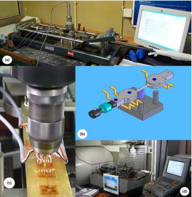
Fig. 1. Experimental setup view. Tensile test machine and ultra-high speed
drilling equipment (a). Grip system, showing the load cell assembly (b). GFRP specimen being drilled (c) using a CNC machining centre (d).
2.2. Numerical work
In this phase, the finite element method (FEM) is used for hole-drilling simulation, following the experimental calibration procedure, as shown in Fig. 2. The numerical model was developed using Parametric Design Language (APDL) for ANSYS 11.0 [11]. Relieved strain-depth curves, FEM(z), corresponding to the
differential calibration stress applied, were numerically calculated. Here, due to ply orientation of the GFRP [+45°/-45°]2s (see section
3), a 3D finite element mesh consisting of a full model, without any symmetry, was developed. Hole drilling was simulated, incrementally, at centre of the FEM model using the element removal technique [11]. The model uses quadratic 20-node 3D layered solid elements SOLID186 [11] to simulate the orientation of the plies in each drilled incremental depth. All geometrical parameters, applied loads and elastic orthotropic properties of each material’s ply are taken into account. Hole-drilling simulation by FEM can generate ideal in-depth strain relaxation curves,
FEM(z), corresponding to cal, where only the geometrical effect
of the hole’s presence on the imposed stress state is considered. It means that the thermo-mechanical loadings induced by real drilling operation were not taken into account. Thus, the difference between the experimental and numerical strain relaxation values, for each incremental depth (z), is an estimation of the residual strain induced by drilling, i.e.:
(z) Δε (z) Δε (z)
Δεdrill EXP FEM . (4)
Residual stress distribution (RS=f(z)) induced by drilling can
further be evaluated. Unfortunately, for FRPs, a theoretical background for residual stress evaluation is not yet well
established for the application of the IHD technique. For anisotropic materials, a valid calculation method should first be developed to enable the evaluation of in depth residual stress distribution based on the obtained drill(z) curves and on suitable
calibration functions determined by FEM, as is already possible to the case of isotropic materials, using, e.g., the integral method [7, 10]. The best approach to this problem was developed by Pagliaro
et al. [5] to analyse the residual stresses in orthotropic laminates
caused by initial in-plane loads. Nevertheless, in this context, the HENM methodology is important at two levels. First, the IHD technique needs to be validated for its application to the polymer matrix composites and, second, to improve the drilling process itself, an aspect also essential for the IHD technique accuracy. Fig.2 shows how the HNEM methodology works and how it can be used for optimization purposes of drilling operations.
Fig. 2. Flowchart for the optimization of the drilling operations. 3. HENM application to a glass-epoxy composite
Specimens (284x29x3[mm]) of glass-epoxy reinforced polymer (GFRP) were manufactured using the symmetric stacking sequence of [+45°/-45°]2s. This produced eight plies with a layer thickness of
375 μm. In-plane elastic properties of individual lamina are [12]: E11=39 GPa, E22=13.3 GPa, G12=5.1 GPa, 12 = 0.25.
An ultra-high speed milling machine (UHSM), powered by a pressurised air turbine system, a drilling procedure usually employed with the hole-drilling method for measuring residual stresses in metallic materials, and a computer numerically controlled milling machine (CNCMM), were selected for the main drilling operations. Table 1 shows the cutting parameters used in the drilling operations. Coated (TiN) cemented carbide end-milling cutters with six teeth and back taper were used in both drilling operations. For the UHSM drilling, the alignment between the end mill and the centre of the hole was achieved using RS-200 milling guide equipment (Vishay®), while a centring finescope was used
for the CNCMM drilling experiments.
Table 1
Drilling parameters
Drilling operation End mills Rotational speed Feed rate
[mm] [rpm] [mm.min-1] UHSM 1.6 ~210,000* <<0.01
CNCMM** 1.6 10,000 0.01
(*) Estimated using Fourier frequency analysis of the sound signal (**) Parameters selected based on [13]
Previously to perform the experimental tests, it is necessary first to select the number of depth increments and their thicknesses, which depend on the specimen and ply thicknesses. For each ply,
at least two depth increments should be considered [6], thus three depth increments per ply were selected. The specimens were clamped and loaded under two different levels of load, leading to a differential calibration stress (cal) equal to 12 MPa.
4. Results and Discussion
Fig. 3 shows the stress-strain behaviour of the material, in the range of the applied loads.
Fig. 3. Experimental nominal stress versus strain during tensile tests.
GFRP material exhibits linear elastic behaviour in all directions, in the range of tensile stress applied. Therefore, the superposition principle is valid and the proposed methodology can be applied. Fig. 4 shows the differential strain relaxation values, corresponding to fapp and iapp measured just after each depth increment. For
+45° and -45° directions similar values were obtained, for both drilling operations.
Fig. 4. Differential strain relaxation values versus depth after drilling.
In the longitudinal direction (0°) higher values are observed and a clear difference between both drilling operations can be seen. UHSM presents lower differential strain relaxation values when compared with CNCMM ones (constant difference of ~200 st). Strain-depth relaxation curves, EXP(z), corresponding to the
calibration stress applied, (cal), can be drawn. It is only necessary
to subtract the initial strain values, corresponding to the lower and greater applied stresses, fapp and iapp, respectively, before
drilling, from the strain measured after each incremental depth
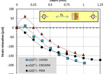
drilled. Figure 5 shows the experimental (corresponding to UHSM and CNCMM) and simulated curves, in the longitudinal direction. This is the direction of the applied stress and, therefore, higher sensitivity and strain values are found, when compared with those strains found at 45°.
Fig. 5. Strain-depth relaxation profiles for the longitudinal direction
(x≡2). Comparative analysis between experimental (UHSM, CNCMM) and
numerical data (FEM).
Fig. 6. Strain-depth relaxation profiles for the 45° direction (3=1).
Comparative analysis between experimental (UHSM, CNCMM) and numerical data (FEM).
For the 45° direction, similar behaviour was observed for the first depth increments and clear discrepancies are observed for deeper layers. However, for this direction, the strain relaxation values are very low and consequently any small measurement error could greatly influence the results. Anyway, it was observed that the qualitative difference between the drilling operations is real and reproducible. Thus, since the applied stress is uniaxial and its direction is known, only this direction really matters when analysing the deviation of the experimental values from the numerical ones, for an assessment of the effect of the drilling operation selected. In the longitudinal direction, all curves present similar behaviour, although some differences can be observed. Having the numerical curves as reference, the differences are clearly greater in the case of CNCMM machining when compared with the UHSM. Nevertheless, despite the differences, the similar behaviour observed for both experimental and numerical curves is an excellent result regarding further use of the incremental hole drilling technique for determining residual stresses in these kinds of materials. Before, the drilling process should be optimized, in
order to minimize the effect of the strains induced by drilling, which were observed and evaluated in this investigation.
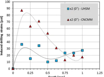
Based on Fig. 5 and equation (4), the strains induced by the drilling process, drill(z), can be estimated for the longitudinal
direction. Fig. 7 is conclusive about the induced drilling strains in both drilling operations. Induced UHSM strains are substantially lower than CNCMM ones. Greater strains seem to be induced in the first drilling steps, decreasing for deeper layers. However, once these values are determined at material’s surface, the gradients arising in both curves are more important than the absolute values shown in Fig. 7. In fact, the induced drilling stresses are related to the strain relaxation gradients, i.e., to the curves’ gradients shown in Fig. 7 [7]. To accurately determine these stresses using the IHD technique, a theoretical background for anisotropic materials must be developed [5, 14].
Fig. 7. Induced drilling strains due to UHSM and CNCMM milling operations
onto GFRP specimens.
The different behaviour observed for both drilling operations is due to the different drilling parameters. The cutting speed used in UHSM drilling was greater than the speed used in CNCMM drilling, but the feed rate was lower (see table 1). In the UHSM operation an intermittent cutting procedure was used. Thus, when the tool touched the sample, it was immediately lifted, allowing a cooling effect around the cutting region due to the air jet leaving the turbine. In the case of CNCMM drilling, the tool was continually engaged in the sample. Thus, the thermo-mechanical loadings induced by CNCMM drilling should be higher when compared with those induced by UHSM drilling.
The vertical cross-section of each hole was also analysed by digital microscopy. Fig. 8 shows a hole drilled by UHSM.
Fig. 8. Micrographs of hole morphology after UHSM drilling.
A uniform cylindrical hole with a flat bottom can be observed. The holes produced by CNCMM had a lower quality when compared with those produced by UHSM. However, no delamination was observed for both drilling operations. This is an
important requirement to accurately determine residual stresses by IHD. Note that the first cutting layer in Fig. 8 corresponds to the glue and material of the strain-gauge.
5. Conclusions
A hybrid experimental-numerical methodology was developed and used to quantify the residual strains induced by two drilling operations (UHSM and CNCMM) of glass-epoxy laminates. In-depth strain relaxation curves corresponding to a well-known applied stress state could be obtained. These experimental curves were further compared with the numerically simulated ones using FEM. The direct comparison between the experimental and numerical curves led to the determination of the residual strains induced by drilling. These strains were greater for the CNCMM drilling, probably due to the stronger thermo-mechanical phenomena induced by such operation. In addition, for both drilling operations, no delamination was observed.
The proposed methodology can be a powerful tool to improve and optimize the drilling process. It can be used to test and study different drilling operations (e.g., orbital drilling), drilling parameters, cooling conditions (e.g., cryogenic cooling) and tool geometries, as a way to reduce the induced drilling strains on the work material and consequently the residual stresses.
Acknowledgments
The authors acknowledge the financial support of German Research Foundation, Project SFB – TRR30, which made this work possible. The financial support of ERDF is also acknowledged.
References
[1] Jawahir IS, Brinksmeier E, M'Saoubi R, Aspinwall DK, Outeiro JC, Meyer D, Umbrello D, Jayal AD (2011) Surface Integrity in Material Removal Processes. CIRP Annals - Manufacturing Technology 60/2:603-626.
[2] White R, Hahn H (1992) Process Modelling of Composite Materials. Part II: Experimental Validation. Journal of Composite Materials 26:2423-2453. [3] Brinksmeier E, Fangmann S, Rentsch R. (2011) Drilling of Composites and
Resulting Surface Integrity. CIRP Annals - Manufacturing Technology 60:57-60. [4] Rawat S, Attia H. (2009) Characterization of the Dry High Speed Drilling Process of Woven Composites using Machinability Maps Approach. CIRP Annals - Manufacturing Technology 58:105–108.
[5] Pagliaro P, Zuccarello B (2007) Residual Stress Analysis of Orthotropic Materials by the Through-hole Drilling Method. Experimental Mechanics 47:217-236.
[6] Sicot O, Gong XL, Cherouat A, Lu J (2003) Determination of Residual Stress in Composite Laminates using the Incremental Hole-drilling Method. Journal of Composite Materials 37:831–844.
[7] Nobre JP, Dias AM, Domingos AJ, Morais R, Reis MJCS (2009) A Windows-Based Software Package to Evaluate Residual Stresses by the Hole-Drilling Technique. Computer Applications in Engineering. Education 17:351–362.
[8] Nobre JP, Stiffel J, Paepegem W, Nau A, Batista A, Marques M, Scholtes B (2011) Quantifying the Drilling Effect During the Application of the Incremental Hole-Drilling Technique in Laminate Composites. Materials Science Forum 681:510-515.
[9] Rendler NJ, Vigness I (1966) Hole-drilling Method of Measuring Residual Stresses, Experimental Mechanics 6:577-586.
[10] ASTM-E-837-08, Standard test method for determining residual stresses by the holle-drilling strain-gage method. Annual Book of ASTM Standards, 1-12 (2008).
[11] Documentation for ANSYS 11, SAS IP, Houston, USA, (2010).
[12] Paepegem W, Baere I, Degrieck J (2006) Modelling the Nonlinear Shear Stress-Strain Response of Glass Fibre-Reinforced Composites. Composites Science Technology 66:1455-1464.
[13] Marques A, Durao L, Magalhães A, Silva J, Tavares J (2010) Delamination Analysis of Carbon Fibre Reinforced Laminates: Evaluation of a Special Step Drill. Composites Science Technology 69:2376-82.
[14] Schajer G, Yang L (1994) Residual-stress Measurement in Orthotropic Materials using the Hole-drilling Method. Experimental Mechanics 34:324-333.