HAL Id: hal-01406355
https://hal.inria.fr/hal-01406355
Submitted on 1 Dec 2016
HAL is a multi-disciplinary open access
archive for the deposit and dissemination of
sci-entific research documents, whether they are
pub-lished or not. The documents may come from
teaching and research institutions in France or
abroad, or from public or private research centers.
L’archive ouverte pluridisciplinaire HAL, est
destinée au dépôt et à la diffusion de documents
scientifiques de niveau recherche, publiés ou non,
émanant des établissements d’enseignement et de
recherche français ou étrangers, des laboratoires
publics ou privés.
Crosstalk noise aware wavelength allocation in WDM
3D ONoC
Jiating Luo, Daniel Chillet, Cédric Killian, Sébastien Le Beux, Ian O ’Connor,
Olivier Sentieys
To cite this version:
Jiating Luo, Daniel Chillet, Cédric Killian, Sébastien Le Beux, Ian O ’Connor, et al.. Crosstalk noise
aware wavelength allocation in WDM 3D ONoC. Colloque National du GDR SoC-SiP, Jun 2016,
Nantes, France. �hal-01406355�
Crosstalk noise aware wavelength allocation in WDM 3D ONoC
Jiating LUO
1, Daniel Chillet
1, C´edric Killian
1, S´ebastien Le Beux
2, Ian O’Connor
2, Olivier Sentieys
11
University of Rennes 1, IRISA, INRIA
2Ecole Centrale de Lyon, INL
Lannion 22300, France
Ecully, F-69134, France
[email protected]
[email protected]
Abstract
Optical Network-on-Chip (ONoC) employs Wave-length Division Multiplexing (WDM) supporting multiple transactions at same time. In this context, many senders and receivers can share the same waveguide to increase the total bandwidth utilization. However, simultaneous transmissions on closed adjacent wavelengths may intro-duce crosstalk noise through different optical switching elements within the network due to the low wavelength channel spacing and the large Full Width at Half Maxi-mum (FWHM) of the resonance pic of the Microring Res-onator (MR). To address this problem, this paper proposes crosstalk noise aware wavelength allocation in WDM 3D ONoC to improve Signal to Noise Ratio (SNR) perfor-mance.
1. Introduction
Given the evolution of MPSoC, we currently focus on chips with hundreds of IP cores. To cope with huge com-munication requirement, Network-on-chip (NoC) design has been put forward to replace bus-based design. How-ever, the limitation of electrical interconnects, such as capacitive and inductive coupling [5], interconnect noise and increased propagation delay of global interconnect, has severely hindered the further improvement of NoC. A 3D architecture based on an optical interconnection for an MPSoC is one of the key solutions to solve the above limitations. It relies on optical waveguides carrying optical signals and provides low latency, high bandwidth properties and high noise immunity to the communication medium. The waveguide for data transmission can be shared by multiple senders and receivers. Moreover, Wavelength Division Multiplexing (WDM) [2] is em-ployed to support multiple transactions at same time.A communication between a source and a destination can be established by using several wevelenghts in parallel in order to reduce the communication time. However, simul-taneous transmissions, on closed adjacent wavelengths, may introduce crosstalk noise through different optical switching elements within the network which degrades system performance [1]. Indeed, Micro Resonators (MR) are used to inject or drop optical signal to the waveguide
to send or receive data. They act like non-ideal filters and drop an amount of power of the optical signals proportional to the distance between the optical signal wavelenght and the resonance wavelength of the MRs. This paper addresses this problem and propose to reduce the crosstalk by an efficient wavelength allocation. Many of the previous research works are focused on developing models at the device level for the worst-case crosstalk noise and SNR in different ONoCs [4] [1]. They demonstrate that the crosstalk noise is a critical concern in large-scale WDM 3D ONoC. To the best of our knowledge, none of previous works have explored wavelength spacing for overlapped communication to minimize crosstalk noise.
2
Crosstalk noise problem
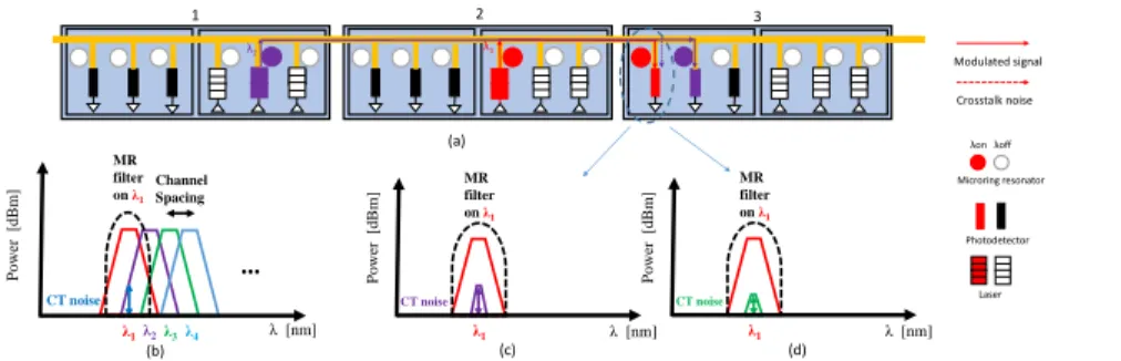
As shown in the example presented in the Fig. 1(a), 3 Optical Network interfaces (ONIs) are crossed by a waveguide with 3 wavelengths. We note λCi,j the
re-served wavelength for a communication between ON Ii
and ON Ij. The crosstalk noise appears because two low
spacing wavelengths λCi,j and λCm,n reach
simultane-ously a on-state MR. Fig. 1(b) shows that the crosstalk noise is higher with the smaller channel spacing between λCi,j and λCm,n. In ON I3, a part of light from λC1,3
is also filtered by on-state MR specific to λ1, introducing
crosstalk noise on optical signal on λ1(red color). In data
transmission, the crosstalk noise decreases SNR which creases the BER of the optical signal. Considering the in-troduction of crosstalk noise is inevitable, it is importance to reduce the affection on SNR. In this example, we have 2 choices (λ2and λ3) for communication between ON I1
and ON I3. Figures 1(c) and 1(d) show the crosstalk noise
introduced by λ2and λ3on M Rλ1of ON I3respectively.
The filtered power of λ3is smaller compared to that of λ2.
Hence we choose λ3for C1,3which leads to a better SNR.
Wavelength allocation is hence vital to reduce crosstalk noise in the network. Our idea is to space out two over-lapped wavelengths as far as possible to maximize SNR in order to be able top reduce the power of laser if a specific BER is targeted.
2 Modulated signal Crosstalk noise λ [nm] Power [dBm] CT noise MR filter on λ1 Channel Spacing λ1λ2λ3λ4 … 1 3 λ [nm] Power [dBm] CT noise MR filter on λ1 λ1 λ1 λ2 λ [nm] Power [dBm] CT noise MR filter on λ1 λ1 (a) (b) (c) (d) λon λoff Microring resonator Photodetector Laser
Figure 1: (a) Communication example ; (b) Crosstalk noise illustration ; Crosstalk noise : (c) if λC1,3= λ2; (d) if λC1,3= λ3
3
Power model
Definition 1: The overlapped communications graph (OCG) for an application is a directed graph, GC = {C, E} with each vertex Ci,jm ∈ C represents the communica-tion between ON Iiand ON Ij on one wavelength λCm
i,j,
and each edge defines the overlapped relationship between λCn
k,l and λC m
i,j. The edge between C
m i,jand C
n
k,lexists if
temporal and spatial conflict for these two communica-tions appear simultaneously. The edge direction means the source signal of crosstalk noise to the detected signal. The weight of edge ECm
i,j,Ck,ln ∈ E can be expressed as
below: ECm i,j,Cnk,l= Pλj Cn k,l Pλj Cm i,j ∀m, n; λCn k,l6= λC m i,j (1) Where Pλj Cn k,l
represents the power of signal carried on λCn
k,l arriving at ON Ij, P
j λCm
i,j
represents the power of signal carried on λCm
i,j arriving at ON Ij. In this case,
Ci,jmarrives at its destination ON Ijand the MR specific to
λCm
i,j is turned on. A portion of the signal carried on λCk,ln
is also filtered by the ON-state MR introducing crosstalk noise on detected signal. Hence, ECm
i,j,Ck,ln indicates the
degree of crosstalk noise of λCn
k,l added on λC m
i,j. We
propose a heuristic algorithm to allocate wavelengths of Edgesort = SortU pDownby edges values(Edge). Our
idea is, like greedy algorithm, to follow the priority of weights of edges and make the locally optimal choice at each step, then find a global suboptimal solution. We derived the signal power at the photodetector in equa-tion (2).
Pλj Cm
i,j
= PLaser+ LM R−of f+ LM R−on+ LP + LB (2)
LPand LBare the propagation and bending losses along
the ON Ii and ON Ij. LM R−of f and LM R−on are the
loss introduced by OFF-state and ON-state MR along the ON Iiand ON Ij.
4
Simulation results
To prove that the choice of wavelengths heavily affects the SNR performance, we consider the following exper-iments. Figure 2 illustrates the mapping of the tasks on
Figure 2: Mapping of the tasks on the different IPs
different IPs. The right-hand side of Figure 2 represents 8 ONIs crossed by one waveguide propagating optical sig-nals. The arrows represent the mapping of 8 tasks onto the IP connected to the ONIs. For example, T0is assigned
to IP0. We assume that 4 wavelengths are integrated in
the waveguide and each communication can reserve one wavelength. The wavelength allocation results by the pro-posed heuristic algorithm based on OCG are resumed in table 1. For example, λ1is allocated to C0,5. The related
SN R is equal to 9.58 dB, compared to 3.85 dB for the naive method [3].
Table 1: Wavelengths allocation results
C0,5 C5,10 C1,7 C7,10 C3,8 C8,10 C1,4 C4,7 C4,10
λ1 λ3 λ3 λ1 λ2 λ4 λ4 λ4 λ1
5. Conclusion
Crosstalk noise heavily affects the SNR performance in Optical network-on-chip. In this paper, we introduce a crosstalk noise aware wavelength allocation model which allows to improve SNR performance.
References
[1] D. et Al. Coherent and incoherent crosstalk noise analyses in interchip/intrachip optical interconnection networks. [2] D. et Al. WDM technologies: Optical networks: Optical
networks. Academic Press, 2004.
[3] L. et Al. Channel allocation protocol for reconfigurable op-tical network-on-chip. In SiPhotonics, 2015.
[4] N. et Al. Crosstalk noise in wdm-based optical networks-on-chip: A formal study and comparison. IEEE Transac-tions on VLSI Systems, 2015.
[5] R. et Al. The future of wires. In Proceedings of the IEEE, 2001.