DOCTORAT DE L'UNIVERSITÉ DE TOULOUSE
Délivré par :Institut National Polytechnique de Toulouse (INP Toulouse) Discipline ou spécialité :
Signal, Image, Acoustique et Optimisation
Présentée et soutenue par :
Mme LESLIE MONTLOIN le jeudi 10 juillet 2014
Titre :
Unité de recherche : Ecole doctorale :
IMPACT OF GNSS SINGULAR EVENTS ON THE INTEGRITY OF
AIRPORT NAVIGATION SYSTEMS
Mathématiques, Informatique, Télécommunications de Toulouse (MITT) Laboratoire de Télécommunications (TELECOM) de l'ENAC
Directeur(s) de Thèse :
M. CHRISTOPHE MACABIAU MME ANAÏS MARTINEAU
Rapporteurs :
M. BERND EISSFELLER, UNIVERSITE FAF MUNICH M. MICHAEL BRAASCH, OHIO UNIVERSITY ATHENS
Membre(s) du jury :
1 M. EMMANUEL DUFLOS, ECOLE CENTRALE DE LILLE, Président
2 M. CHRISTOPHE MACABIAU, ECOLE NATIONALE DE L'AVIATION CIVILE, Membre
2 M. LAURENT AZOULAI, AIRBUS FRANCE, Membre
2
ACKNOWLEDGMENTS
This work has been carried out in the GNSS and Signal Processing Group of the TELECOM Lab at the ENAC. I acknowledge ANRT and Airbus for funding this thesis.
I am grateful to Bernd Eissfeller and Michael. S. Braasch for accepting to review the thesis, and to Emmanuel Duflos for accepting to be part of the jury. Thank you for the interest you have shown in my thesis, for your comments and advices on the manuscript, and of course for coming to my Ph.D. defense.
I would like to thank my ENAC thesis directors: Christophe Macabiau, Carl Milner, Anaïs Martineau, Alexandre Chabory for their advices all along this work and for the technical discussions. Thank you to Alexandre for the technical support on EM. I would like to warmly acknowledge Carl for his constant support and enthusiasm during these last two years, for his availability even during the busy days, and for the time he spent on my papers and on my manuscript.
I am also very grateful to Laurent Azoulai, my Airbus supervisor, for his involvement in my project, for the technical and operational advices, and for his constant support all along my thesis. I acknowledge Adrien Chen for the technical support on the multipath error modeling part and Pierre Néri for his help. Thank you also to Sandra Poussin and Genevièvre Oudart for the opportunity to do my Ph.D. for Airbus, and to Laetitia Olivier and Michel Bovet for their encouragement and for the interest they showed in the project. I acknowledge the Airbus radio-navigation team EYAN3 for the good atmosphere and for the good time we spent in Ax-les-Thermes.
Several ENAC students have also been involved in the thesis. Thank you to Ma Long for the 3D model of Blagnac airport, Quentin Tessier for his important help concerning the ION GNSS 2012 paper, Christophe Charbonnieras and Thomas Longo for their work on new GPS and Galileo signals, Antoine Plainard for his contribution concerning the simulation results proposed in this manuscript, the Master GNSS 2013 students for their work on the validity of the 3D model of Toulouse Blagnac.
I am very grateful to the ENAC SIGNAV and EMA labs. I would specially thank Jérémy Vézinet for all the technical discussions and for his constant help on the Kalman filtering. I acknowledge Olivier Julien, Anne-Christine Escher, Lina Deambrogio, Daniel Salos, Myriam Foucras, Philippe Brocard for their support on hybridization, integrity, maths, signal processing. Thank you so much to my ENAC/Supaero/ENSICA friends for all the memories in Nashville, for the bowling matches in Balma, for the restaurants in Toulouse, for the “pantagruélique” dinner in Saint Orens, and of course for the moral support during the thesis:
3
thank you to Myriam, Lina, Amani, Alizé, Philippe, Paulo, Seb Carca, Seb Roche, Jérem, Jérôme, ... .
I warmly acknowledge the Imajing team. Thank you to Etienne Lamort de Gail for his support and for the advices concerning the defense, thank you to my new colleagues for the very good atmosphere that helped me to relax for the defense: Yvonnic, Marie-Anne, Bruno, Quentin... Finally, thank you so much to my parents and to my sisters for their listening and for their moral support all along the thesis. I acknowledge the rest of my family and my friends for the good times we spent together. Thank you to Seb R. for his Patience and constant encouragement and during this last year.
i
ABSTRACT
Global Navigation Satellite Systems (GNSSs) are currently used in civil aviation to provide aircraft with position and velocity estimates from en-route to Precision Approach (PA) operations. GNSSs are also used during surface operations for the position awareness. The taxi operation consists in three sub-phases: the taxi on taxiway, the taxi on apron taxiway and the taxi on taxi lane (gate phase) sub-phases. The position awareness function requires a visual check of the airport environment by pilots. Extending the use of GNSS to the guidance function during airport surface operations and under zero-visibility conditions remains a challenge. Indeed, during these operations, GNSS measurements may be affected by GNSS singular events, such as multipath or ionosphere anomalies. GNSS singular events may lead to unacceptable position errors in terms of accuracy and integrity for the zero-visibility guidance function. Current GNSS integrity monitoring systems are not designed to totally account for the GNSS singular event effects. The assessment of the GNSS singular event effects on the accuracy and integrity of GNSS-based airport surface navigation systems and the development of GNSS mitigation and integrity monitoring systems designed to properly protect users from the singular event effects are thus essential.
GNSS measurement error and integrity failure models are key inputs in the design of GNSS integrity monitoring systems. In this thesis, work has been mainly focused on the modelling of GNSS multipath measurement errors, on the assessment of the multipath impact on the GNSS-based position error, and on the development of GNSS multipath integrity failure models.
For this matter, the dual frequency GPSL1C+GPSL5 and GalileoE1+GalileoE5a multipath pseudo-range error model adapted to airport navigation has been proposed, when the aircraft is parked or is moving in the airport environment. Three multipath sources are considered in this thesis: the airport surface, the aircraft structure and the airport buildings and gates. The multipath ranging error is modelled as the sum of a deterministic bias (induced by the aircraft structure itself and the airport surface) and of a stochastic error (induced by the airport obstacles).
Next, the analysis of the impact of multipath on the GNSS-based position error has been proposed. The first step consists in choosing a GNSS-based positioning algorithm suitable for the zero-visibility airport guidance application. A double constellation Global Positioning System (GPS)+Galileo/Inertial Reference System (IRS)/Digital Elevation Map (DEM) tight coupling algorithm based on a linearized Kalman filter has been selected. The horizontal position error at the output of this positioning algorithm can be over-bounded by a bi-dimensional Gaussian distribution characterized by a bias vector and by a covariance matrix. Secondly, the theoretical analysis of the impact of the GNSS deterministic multipath ranging errors on the horizontal position bias and of the GNSS multipath stochastic ranging errors on the covariance matrix of the horizontal position error are assessed. The third step is the quantification by simulations of the multipath impact on both horizontal position bias and
ii
covariance matrix along with the assessment of the accuracy performance of the positioning algorithm in the presence of multipath throughout a given taxi procedure path at Toulouse Blagnac airport, France.
The results associated with the proposed position error models are as follows. The deterministic multipath ranging errors are dependent on the elevation mask angles and induce a horizontal position bias equal to a few centimeters up to a few decimeters. Moreover, the presence of a stochastic multipath error on a single GNSS measurement induces an inflation of the covariance matrix of the horizontal position error of a few millimeters up to a few centimeters, depending on the stochastic parameters (standard deviation, correlation time) that characterize the stochastic multipath ranging error. From the accuracy analysis, the positioning algorithm is not suitable for the taxi on taxi lane phase (gate operations).
Finally, a GNSS multipath integrity failure model has been proposed for both taxiway and apron operations along a given procedure path at Blagnac airport. The developed failure model describes the characteristics in terms of standard deviation and correlation time of the GNSS single multipath ranging failures, the occurrence model of the GNSS single multipath ranging failures and their conditions of occurrence. Under the assumptions stated in the thesis, and particularly in the absence of mobile obstacles in the scene, such as other parked aircraft, GNSS single ranging failures do not occur during both taxiway and apron operations along the considered procedure path at Blagnac airport.
i
RESUME
Les systèmes de navigation par satellites (GNSS) sont actuellement utilisés en aviation civile pour estimer la position et la vitesse des avions pour les opérations en-route jusqu’aux approches de précison. Les systèmes GNSS sont également utilisés pendant les opérations de surface pour la fonction « position awareness ». Les opérations de surface regroupent trois sous-phases, qui sont la phase de « taxi on taxiway », la phase de « taxi on apron taxiway » et la phase de « taxi on taxilane ». La fonction « position awareness » oblige les pilotes à effectuer une vérification visuelle de l’environnement aéroportuaire. L’utilisation des systèmes GNSS pour guider l’avion pendant les opérations de surface et dans les conditions de zéro-visibilité reste un challenge pour la communauté aviation civile. En effet, durant les opérations de surface, les mesures GNSS peuvent être affectées par des évènements singuliers GNSS, tels que les multi trajets ou les anomalies ionosphériques. Les évènements singuliers GNSS peuvent engendrer des erreurs de positionnement jugées inacceptables en termes de précision et d’intégrité pour la fonction de guidage de l’avion en environnement aéroportuaire et sous les conditions de zéro-visibilité. Les systèmes de contrôle d’intégrité GNSS utilisés actuellement ne sont pas conçus pour prendre en compte les effets de tels évènements singuliers. L’analyse des effets des évènements singuliers sur la précision et sur l’intégrité des systèmes de navigation aéroportuaires basés sur les systèmes GNSS et le développement de systèmes de contrôle d’intégrité GNSS conçus pour protéger les utilisateurs des évènements singuliers GNSS sont donc essentiels.
Les modèles d’erreurs de mesures GNSS et les modèles de pannes sont essentiels pour la conception de systèmes de contrôle d’intégrité GNSS. Dans cette thèse, les travaux se sont principalement focalisés sur la modélisation des erreurs de mesures GNSS dues aux multi trajets, sur l’analyse de l’impact des multi trajets sur l’erreur de positionnement, et sur le développement d’un modèle de pannes multi trajets.
Pour cela, les modèles d’erreurs multi trajets sur les pseudo-distances GNSS bi-fréquence GPSL1C+GPSL5 et GalileoE1OS+GalileoE5a sont proposés. Ces modèles sont adaptées au cas où l’avion est statique dans l’environnement aéroportuaire, et au cas où l’avion se déplace dans l’environnement aéroportuaire. Trois sources de multi trajets sont considérées dans la thèse : la surface de l’aéroport, la structure de l’avion sur lequel est monté l’antenne GNSS, et les bâtiments de l’aéroport. L’erreur multi trajets est modélisée comme la somme d’un biais déterministe (induit par la structure de l’avion et la surface de l’aéroport), et une erreur stochastique (induite par les bâtiments de l’aéroport).
Ensuite, l’analyse de l’impact des multi trajets sur l’erreur de positionnement est proposée. La première étape consiste à choisir l’algorithme de positionnement GNSS adapté à la fonction de guidage des avions dans un environnement aéroportuaire et sous les conditions de zéro-visibilité. Un algorithme double constellations Global Positioning System (GPS) + Galileo / Inertial Référence System (IRS) / Digital Elevation Map (DEM) basé sur un filtrage de Kalman linéarisé a été sélectionné. La deuxième étape consiste à analyser l’impact des multi
ii
trajets sur la position horizontale estimée en sortie du filtre de Kalman. L’erreur de position horizontale en sortie de filtre de Kalman peut être modélisée comme une distribution Gaussienne bidimensionnelle caractérisée par un biais et par une matrice de covariance. L’impact des erreurs multi trajets sur le biais et sur la matrice de covariance de l’erreur de position horizontale est analysé de manière qualitative. La troisième étape est la quantification pas simulations de l’impact des multi trajets sur le biais et sur la matrice de covariance de l’erreur de position horizontale, ainsi que l’étude de la performance de l’algorithme de positionnement en termes de précision le long d’une procédure de taxi sur l’aéroport de Toulouse Blagnac, en France.
Les résultats associés à l’analyse de l’impact des multi trajets sur l’erreur de positionnement sont les suivants. La partie déterministe de l’erreur multi trajets sur les mesures GNSS induit un biais sur la position horizontale estimée par le filtre de Kalman. Ce biais dans le domaine de la position est de quelques centimètres et peut atteindre quelques décimètres. De plus, la partie stochastique de l’erreur multi trajets sur les mesures GNSS induit une inflation de la matrice de covariance de l’erreur de position horizontale en sortie de filtre de Kalman. Cette inflation peut atteindre quelques centimètres en écart type, et dépendant des caractéristiques (écart type, temps de corrélation) de l’erreur stochastique de multi trajets sur les mesures GNSS. Concernant les performances de l’algorithme de positionnement en termes de précision, l’algorithme sélectionné n’est pas adapté à la phase « taxi on taxi lane ».
Finalement, un modèle de pannes multi trajets est proposé pour les sous phase de « taxi on taxiway » et de « taxi on apron taxiway ». Le modèle de pannes développé décrit les caractéristiques des pannes simples multi trajets en termes d’écart type et de temps de corrélation, le modèle d’occurrence des pannes simples multi trajets, ainsi que les conditions d’occurrence de telles pannes. En tenant compte des hypothèses décrites dans la thèse, et particulièrement en l’absence d’obstacles mobiles dans la scène aéroportuaire, les pannes simples multi trajets ne se produisent pas le long des phases de « taxi on taxiway » et de « taxi on apron taxiway » sur la procédure de taxi sélectionnée dans l’aéroport de Toulouse Blagnac, en France.
iii
TABLE OF CONTENTS
ACKNOWLEDGMENTS ... 2
ABSTRACT ... i
RESUME ... i
TABLE OF CONTENTS ... iii
LIST OF FIGURES ... ix
LIST OF TABLES ... xiii
CHAPTER 1: Introduction ... 1
1.1. Motivations ... 1
1.2. Objectives ... 4
1.3. Contributions ... 4
1.4. Thesis outline ... 5
CHAPTER 2: Civil aviation requirements ... 9
2.1. Phases of flight definitions ... 10
2.1.1. Definitions ... 10
2.1.2. Approach and landing operations categories ... 11
2.1.3. Taxi operation and related functions ... 12
2.2. Requirements presentation ... 14
2.2.1. Total system performance requirements ... 14
2.2.2. Navigation system performance requirements ... 15
2.2.3. SIS navigation performance requirements ... 16
2.2.4. Criteria ... 16
2.3. Navigation performance requirements ... 18
2.3.1. ICAO SIS navigation performance requirements ... 18
2.3.2. Navigation system performance requirements for taxi operation ... 19
2.4. Conclusions ... 23
CHAPTER 3: GNSS signals, measurement models and augmentation systems ... 25
3.1. GNSS constellations and GNSS signals ... 25
3.1.1. GNSS constellations ... 25
3.1.2. GNSS signals ... 27
iv
3.2.1. GNSS nominal ranging errors ... 34
3.2.2. GNSS ranging failures ... 46 3.2.3. Case of study ... 56 3.3. GNSS augmentation systems ... 57 3.3.1. Systems presentation ... 57 3.3.2. Case of study ... 58 3.4. Conclusions ... 59
CHAPTER 4: Impact of multipath on GNSS measurements ... 61
4.1. Transmission channel modeling ... 61
4.1.1. Definition ... 61
4.1.2. Transmitter antenna ... 62
4.1.3. Multipath propagation channels ... 62
4.1.4. Receiver antenna ... 63
4.1.5. Transfer function of the transmission channel ... 63
4.1.6. Multipath parameters definition and computation ... 65
4.2. GNSS receiver ... 66
4.2.1. GNSS receiver architecture ... 66
4.2.2. Radio-Frequency front-end ... 67
4.2.3. Intermediate frequency processing ... 67
4.2.4. GNSS receiver settings ... 70
4.3. Impact of multipath on GNSS code pseudo-range measurements ... 71
4.3.1. Impact of multipath on the code delay estimate ... 71
4.3.2. Impact of multipath on the code pseudo-range measurements ... 72
4.4. Conclusions ... 77
CHAPTER 5: GNSS multipath ranging error models ... 79
5.1. GNSS multipath ranging error computation ... 79
5.1.1. GNSS multipath ranging error simulator architecture ... 79
5.1.2. Input parameters of the GNSS multipath ranging error simulator ... 81
5.1.3. First and second-order interactions ... 85
5.1.4. Limitations ... 86
5.2. Simulations scenario ... 86
5.2.1. Low Visibility Procedure path ... 87
5.2.2. Aircraft dynamic ... 88
5.3. Static and dynamic configurations ... 88
5.3.1. Static configuration and steady-state ... 88
5.3.2. Dynamic configuration ... 89
v
5.4.1. Error due to the ground and the aircraft structure ... 92
5.4.2. Error due to the ground, the aircraft structure and the obstacle(s) ... 94
5.5. Multipath error models in dynamic configuration ... 105
5.5.1. Error due ground and aircraft structure ... 106
5.5.2. Error due to ground, aircraft structure and obstacle(s) ... 108
5.6. Conclusions ... 117
CHAPTER 6: GNSS-based positioning algorithm ... 119
6.1. Choice of the positioning algorithm architecture ... 119
6.1.1. Review of Position Velocity Time estimation techniques ... 119
6.1.2. Review of navigation sensors/signals of opportunity ... 120
6.1.3. Review of GNSS/IRS coupling techniques ... 121
6.1.4. Synthesis ... 122
6.2. GNSS/IRS/DEM position error computation ... 123
6.2.1. Trajectory simulator module ... 123
6.2.2. GNSS module ... 124
6.2.3. Inertial module ... 126
6.2.4. Digital Elevation Map module ... 128
6.2.5. Kalman filter module ... 129
6.3. Conclusions ... 137
CHAPTER 7: Impact of multipath on the position error... 139
7.1. Theoretical multipath impact on the position error ... 139
7.1.1. Notations ... 139
7.1.2. Methodology ... 140
7.1.3. Multipath impact on the state vector estimate error ... 141
7.1.4. Multipath impact on the expectation of the position error ... 143
7.1.5. Multipath impact on the covariance of the position error ... 144
7.2. Quantification of the multipath impact on the position error ... 145
7.2.1. Multipath impact on the expectation of the position error ... 145
7.2.2. Multipath impact on the covariance of the position error ... 150
7.3. Evaluation of accuracy performance ... 155
7.3.1. Objective and limitations ... 155
7.3.2. Methodology ... 156
7.3.3. Simulation results ... 160
7.4. Conclusions ... 165
CHAPTER 8: GNSS multipath integrity failure model ... 167
8.1. Integrity concept ... 167
vi
8.1.2. GNSS integrity failure model and GNSS integrity monitoring system design 170
8.2. GNSS multipath integrity failures ... 175
8.2.1. Definitions ... 175
8.2.2. Case of study ... 176
8.2.3. Methodology for GNSS multipath single failure identification ... 176
8.2.4. GNSS multipath failure identification at Toulouse Blagnac airport ... 180
8.3. Presence of GNSS multipath ranging failures ... 184
8.3.1. Occurrence model for GNSS multipath failure ... 184
8.3.2. Presence of GNSS multipath failure at Toulouse Blagnac airport ... 187
8.4. Conclusions ... 192 CHAPTER 9: Conclusions ... 193 9.1. Summary ... 193 9.2. Future work ... 196 REFERENCES ... 201 ACRONYMS ... 213
APPENDIX A: GNSS multipath parameters and ranging errors ... 217
A.1. Multipath parameters of an echo signal scattered by a single point reflector ... 217
A.1.1. Relative code delay ... 218
A.1.2. Relative phase shift ... 220
A.2. Multipath parameters of an echo signal reflected from the ground... 220
A.2.1. Relative Doppler frequency ... 220
A.2.2. Relative phase shift ... 222
A.3. Multipath code tracking error in the presence of a single multipath ... 222
A.4. Multipath ranging error induced by the ground and the aircraft structure ... 225
A.5. Dynamic multipath ranging error model induced by the ground and the aircraft structure during turns ... 226
A.5.1. Extended error model to curved line trajectories ... 227
A.5.2. Horizontal position biases obtained by the extended error model ... 228
APPENDIX B: GNSS stochastic multipath ranging error models... 231
B.1. Validity of the 3D model of Toulouse Blagnac airport ... 231
B.1.1. Previous work ... 232
B.1.2. Representation of facades with meter-level overhangs and recesses ... 233
B.2. Convergence test for the estimation of ... 238
B.3. Impact of the GNSS signal on the estimation of and ... 239
B.4. Comparison of the PSD of along two distinct trajectories ... 240
APPENDIX C: Navigation sensor review... 243
APPENDIX D: GPS and Galileo link budget... 245
vii
D.2. Atmospheric and polarization losses ... 245
D.3. Satellite amplifier output power ... 246
D.4. Satellite antenna gain ... 247
D.5. Free space losses ... 247
D.6. Receiver antenna gain ... 247
APPENDIX E: Impact of multipath on the GNSS-based position error ... 249
E.1. Impact of multipath on the Kalman filter state vector estimate error ... 249
E.2. Expectation of the horizontal position error ... 252
E.3. Covariance matrix of the horizontal position error ... 253
E.4. Analysis of ... 256
E.4.1. Evaluation of the covariance matrix ... 257
E.4.2. Correlation time of the GNSS/IRS/DEM position errors ... 259
APPENDIX F: Reference frames ... 261
F.1. Inertial reference frame – (I) ... 261
F.2. Earth-Centered Earth-Fixed (ECEF) reference frame ... 261
F.3. NED Navigation reference frame – (NED) ... 261
F.4. Wander Azimuth Navigation reference frame – (w) ... 261
F.5. Aircraft body reference frame – (b) ... 262
APPENDIX G: GNSS/IRS/DEM/WSS positioning algorithm ... 263
G.1. GNSS/IRS/WSS positioning error computation ... 263
G.1.1. GNSS/IRS/DEM/WSS positioning error simulator architecture ... 263
G.1.2. Trajectory simulator module ... 264
G.1.3. WSS module ... 265
G.1.4. Kalman filter module ... 266
G.2. Analysis of the GNSS/IRS/DEM/WSS positioning error ... 270
G.2.1. Simulation scenario ... 270
G.2.2. Simulation results ... 271
ix
LIST OF FIGURES
Figure 2-1 : Apron and maneuvering areas at Toulouse Blagnac airport ... 13
Figure 2-2: Departure and arrival taxi sub-phases ... 13
Figure 2-3 : Total System Error [ICAO, 2008] ... 15
Figure 2-4: TSE requirements allocation ... 16
Figure 2-5 : Derivation of the navigation system performance requirements ... 20
Figure 3-1: GPS and Galileo frequency bands ... 28
Figure 3-2: Autocorrelation functions of GPS and Galileo signals... 33
Figure 3-3: PSD functions of GPS and Galileo signals ... 33
Figure 3-4: Standard deviation of the code thermal noise ranging error - ... 41
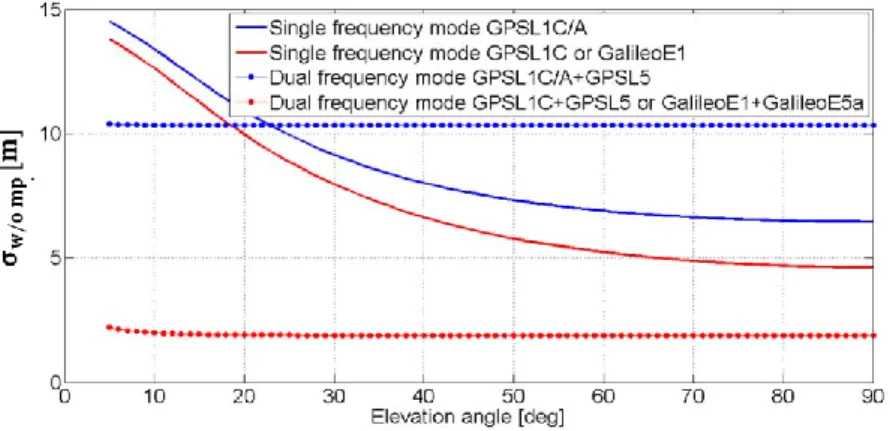
Figure 3-5 : Standard deviation of the nominal code ranging error in the absence of multipath, , Toulouse (France) latitude ... 46
Figure 4-1: Propagation channel and transmission channel ... 62
Figure 4-2: GNSS receiver architecture ... 67
Figure 4-3: General structure of a DLL ... 68
Figure 4-4: Normalized correlator outputs for GPSL5 – absence of multipath ... 71
Figure 4-5: Normalized correlator outputs for GPSL5 – presence of a single echo signal ... 72
Figure 4-6 : Multipath errors envelope for GPSL5 and GalileoE5a signals ... 73
Figure 4-7 : Multipath errors envelope for GPSL1C and GalileoE1 signals ... 74
Figure 4-8 : Multipath code tracking errors for GPSL5 and GalileoE5a signals ... 75
Figure 4-9: Multipath code tracking errors for GPSL1C and GalileoE1 signals as a function of the relative code delay ... 76
Figure 5-1 : Architecture of the deterministic GNSS multipath ranging error simulator ... 80
Figure 5-2: 3D modeling of the terminal buildings and terminal gates of Toulouse Blagnac airport, France ... 82
Figure 5-3: 3D L1 gain pattern of the GPS antenna mounted on a A319 aircraft... 84
Figure 5-4: 2D L1 gain pattern of the GPS antenna mounted on a A319 aircraft... 85
Figure 5-5: LVP path at Toulouse Blagnac airport, France ... 87
Figure 5-6: GNSS receiver antenna height and façade height representation ... 87
Figure 5-7: Raw code multipath ranging error in the static configuration ... 89
Figure 5-8: Raw code multipath ranging error in the static and dynamic configurations ... 90
Figure 5-9: Simulated multipath ranging error GPSL1C+GPSL5 in steady state at Toulouse Blagnac airport, France ... 91
Figure 5-10: Dual-frequency multipath ranging error due to the airport surface and the aircraft structure ... 94
Figure 5-11: Histograms of the L1 relative amplitude of the echo signals ... 95
Figure 5-12: Evolution of the multipath ranging error in steady-state over segment 3 ... 96
Figure 5-13: Evolution of the multipath parameters of echo signal “2” over segments [CD] and [ED] ... 98
x
Figure 5-14: Evolution of the GPSL1C+GPSL5 multipath ranging error over segments [CD]
and [ED] ... 99
Figure 5-15: Methodology to model of in the impact zone ... 101
Figure 5-16: Random position of the GNSS receiver antenna in the impact zone ... 102
Figure 5-17 : Estimated and over-bounding Gaussian PDFs of in the impact zone .... 103
Figure 5-18: as a function of the satellite elevation angle ... 104
Figure 5-19: as a function of the satellite azimuth angle, ... 105
Figure 5-20: Static and dynamic impact zones ... 109
Figure 5-21: L1 and L5 dynamic relative phase shifts over segment [DE] on segment 4 ... 110
Figure 5-22: GPSL1C+GPSL5 multipath ranging errors over segment [CD] and [ED] ... 110
Figure 5-23: Methodology to derive the multipath error model in the impact zone – dynamic configuration ... 112
Figure 5-24 : First-order Gauss-Markov process PSDs and estimated PSD of in the impact zone on segment ... 115
Figure 5-25: as a function of the aircraft speed, , ... 116
Figure 5-26: as a function of the satellite elevation angle, , .. 116
Figure 5-27: as a function of the satellite azimuth angle, , ... 117
Figure 6-1: Architecture of the GNSS/IRS/DEM positioning error simulator ... 123
Figure 6-2: General architecture of the GNSS module ... 124
Figure 7-1: Architecture of the GNSS/IRS/DEM tight coupling positioning algorithm ... 140
Figure 7-2: LVP path at Toulouse Blagnac airport, France ... 146
Figure 7-3: Aircraft azimuth angle and of the multipath ranging error for PRN 4 and PRN 62 satellites ... 148
Figure 7-4: Expectation of the horizontal position error ... 149
Figure 7-5 : Standard deviations of the North and East position errors induced by the multipath stochastic ranging error on PRN 62 ... 152
Figure 7-6: Steady state standard deviations of position errors induced by multipath as a function of ... 154
Figure 7-7: Steady state standard deviations of position errors induced by multipath as a function of ... 154
Figure 7-8: Representation of a surface operation ... 157
Figure 7-9: over three days on segments 1, 3 and 4 ... 162
Figure 7-10: Mean number of satellites and mean PDOP along segment 3 for each constellation configuration ... 163
Figure 7-11: Norm of the horizontal position bias along segment 3 for each constellation configuration ... 163
Figure 8-1 : Methodology to identify the GNSS multipath single ranging failures ... 178
Figure 8-2: Scenario to identify the worst case probability of positioning failure ... 179
Figure 8-3: Worst case probability of positioning failure in the presence of a stochastic multipath ranging error on a single GNSS pseudo-range measurement ... 182
Figure 8-4: Pairs characterizing the GNSS single multipath ranging failures .. 183
Figure 8-5: Impact zone related to satellite and positions of the GNSS airborne antenna .. 185
Figure 8-6: Taxi on taxiway and taxi on apron taxiway segments along the LVP procedure path ... 188
Figure 8-7 : First-order Gauss-Markov process parameters for different aircraft speeds, satellite elevation angles and satellite azimuth angles ... 191
Figure A-1 : Description of the scenario ... 218
Figure A-2 : Early and Late auto-correlation functions ... 223
Figure A-3: Dual-frequency raw code multipath ranging error due to the airport surface and the aircraft structure ... 225
xi
Figure A-4: EM waves scattered by the wing or by the vertical empennage ... 226
Figure A-5: Aircraft azimuth angle and GNSS multipath ranging error induced by the aircraft structure and by the airport obstacle ... 228
Figure A-6 : Aircraft azimuth angle and GNSS multipath position biases induced by the aircraft structure and by the airport obstacle ... 229
Figure B-1 : Representation of the single façade ... 233
Figure B-2: Representation of the null and low resolution concrete facades ... 234
Figure B-3: Power of the EM field scattered on the L1 frequency band ... 235
Figure B-4 : GPSL1C+GPSL5 ranging error along segments [AB] and [CD] in the static configuration ... 236
Figure B-5 : GPSL1C+GPSL5 ranging error along segments [AB] and [CD] in the dynamic configuration ... 236
Figure B-6: Estimated standard deviation of the Gaussian distribution that over-bounds over the impact zone on segment 4 ... 238
Figure B-7: Histograms of the L1 relative code delays of the direct and echo signals ... 239
Figure B-8 : Estimated PSD of in the impact zone on segment 4 ... 241
Figure C-1 : Advantages and drawbacks of navigation sensors and signals of opportunity .. 244
Figure E-1: Methodology to estimate the covariance matrix ... 258
Figure E-2: Normalized autocorrelation functions of the GNSS/IRS horizontal position errors ... 259
Figure F-1 : ECEF and NED and wander azimuth reference frames ... 262
Figure F-2 : Aircraft body reference frame ... 262
Figure G-1 : Architecture of the GNSS/IRS/DEM/WSS positioning error simulator ... 264
Figure G-2: Representation of the procedure path for Figure G-3 ... 271
xiii
LIST OF TABLES
Table 2-1: Minimum values of DH, visibility and RVR for approach and landing operations 12
Table 2-2: SIS performance requirements ... 18
Table 2-3: FTE standard deviation values ... 20
Table 2-4: Navigation system performance requirements – guidance function – category F airports ... 21
Table 2-5: Surface exposure times ... 21
Table 2-6: Updated navigation system performance requirements – guidance function – category F airports ... 22
Table 3-1: Current and future GNSS constellations ... 26
Table 3-2: Characteristics of the GPS and Galileo signals ... 30
Table 3-3: GNSS receiver parameters ... 41
Table 3-4: Causes and magnitude of GNSS multipath induced errors ... 44
Table 3-5: Causes and magnitude of errors induced by GNSS airborne antenna group delay variations ... 45
Table 3-6: Causes and magnitude of single ranging failures caused by control and space segment events ... 48
Table 3-7: Causes and magnitude of multiple ranging failures caused by common control and space segment failure modes ... 49
Table 3-8: Causes and magnitude of ranging failures caused by amplitude scintillations... 51
Table 3-10: Causes and magnitude of ranging failures caused by irregular TEC gradients .... 52
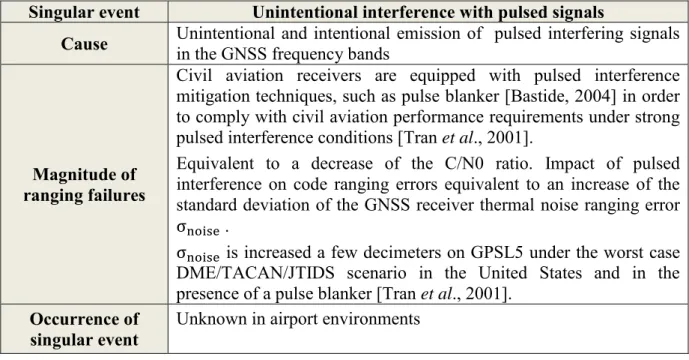
Table 3-11: Causes and magnitude of ranging failures caused by pulsed interfering signals .. 53
Table 3-12: Causes and magnitude of ranging failures caused by CW interfering signals ... 54
Table 3-13: Causes and magnitude of ranging failures caused by wideband and narrowband interfering signals ... 54
Table 3-14: Causes and magnitude of ranging failures caused by intentional interfering signals ... 55
Table 4-1: GNSS receiver parameters setting ... 70
Table 5-1: Assumed characteristics of the concrete and glass facades ... 83
Table 5-2: Taxi speeds ... 88
Table 5-3: Simulation parameters used for Figure 5-7... 88
Table 5-4: 99% response time related to the evolution of the raw code multipath ranging error ... 89
Table 5-5: Simulation parameters used for Figure 5-9... 91
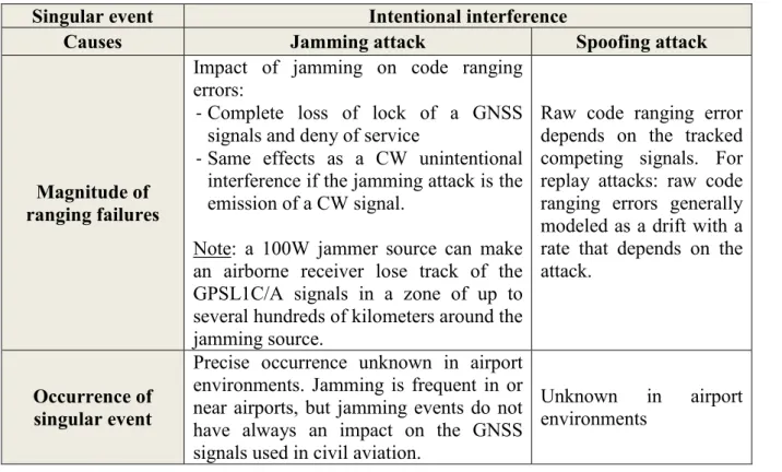
Table 5-6: Maximal variations of the multipath parameters and error from the ground echo signal along a 1km segment ... 92
Table 5-7: Simulation parameters used for Figure 5-11... 95
Table 5-8: Simulation parameters used for Figure 5-13... 97
Table 5-9: Peak-to-peak amplitude of the GPSL1C+GPSL5 multipath ranging error over segment [ED] ... 100
xiv
Table 5-11: Maximal variation of the dual-frequency raw code multipath ranging errors in the
dynamic configuration over a 30 meter long portion ... 107
Table 5-12 : Optimal for different simulation scenarios... 115
Table 6-1: Extension of Kalman filter equations to non-linear systems ... 133
Table 7-1: Taxi speeds used along the LVP path ... 146
Table 7-2: Satellite elevation and azimuth angles for PRN 4 and PRN 62 satellites ... 148
Table 7-3: Elevation mask angles for configurations 1 and 2 ... 149
Table 7-4: Characteristics of the Gauss-Markov process for PRN 62 satellite ... 151
Table 7-5: 99% response time related to the the position error variances ... 153
Table 7-6 : Percentage of satellite geometries for which and mean over all simulated satellite configurations ... 162
Table 8-1 : Integrity navigation system performance requirements – guidance function – category F airports ... 168
Table 8-2: Simulation settings for Figure 8-3 and Figure 8-4 ... 181
Table 8-3: Worst case probability of positioning failure in the absence of a multipath from airport obstacles ... 182
Table A-1: Description of the scenario ... 218
Table A-2 : Analytical expressions of the Early and Late auto-correlation functions ... 224
Table A-3 : Simulation parameters for Figure A-5 ... 227
Table A-4 : Simulation parameters for Figure A-6 ... 229
Table B-1 : Simulation parameters used for Figure B-3 to Figure B-5 and Table B-2 ... 233
Table B-2: Comparison of the static and dynamic model parameters for the null resolution and low resolution concrete facades ... 237
Table B-3: Simulation parameters used for Figure B-7 and Table B-4 ... 240
Table B-4: Comparison of between GPSL1C+GPSL5 and GalileoE1+GalileoE5a 240 Table D-1 : Power losses introduced by the satellite filters and by the payload components imperfections ... 245
Table D-2: Atmospheric and polarization losses ... 246
Table D-3: Computation of the minimum power of the signal at the satellite amplifier output ... 247
Table E-1: Number of GNSS/IRS position errors used in the estimation of ... 258
Table E-2: Estimated correlation times of the GNSS/IRS position errors ... 260
Table G-1 : Simulation settings for Figure 3 ... 270
Table G-2 : Accuracy performance of the GNSS/IRS/DEM/WSS algorithm and of the GNSS/IRS/DEM algorithm – Elevation mask angle 15° for GPS and Galileo ... 272
1
CHAPTER
1
1.
Introduction
1.1. Motivations
The constant growth of the traffic density in airports and the complex architecture of some airports induce operational errors during airport surface operations. As illustrations of operational errors there are runway incursions that may lead to aircraft collisions. The United States Federal Aviation Administration (FAA) has recorded a mean of 20 aircraft collisions a year [FAA, 2013], leading to FAA recommendations to mitigate the collision risks. Hence, there is a need to make the surface operations safer while maintaining the airport capacity under critical conditions that are:
- low visibility conditions, - high traffic density conditions.
Therefore, advanced capabilities are needed to ensure safety and to maintain aerodrome capacity in all weather conditions. In order to provide these advanced capabilities, Surface Movement Guidance and Control Systems (SMGCSs) are developed. SMGCSs should be capable of assisting aircraft to maneuver safely and efficiently on the airport surface and should support four primary functions that are defined as follows [RTCA, 1999]:
- The guidance function provides guidance necessary for movements through clear and continuous indications allowing pilots or autopilots to maintain their positions on the intended routes and for situational awareness.
- The surveillance function captures the information on aircraft, vehicles, and objects within the coverage area and updates data needed for guidance and control.
- The routing function provides assignment of a route to individual aircraft, which provide safe and efficient movement for its current position to its intended final position.
- The control function provides a safe and efficient means of managing movements and planning for requested movements, detects conflicts/incursions and provides solutions. Estimating the position of aircraft present in airport environments is of primary importance for both guidance and surveillance functions. It is thus required to design navigation systems that estimate aircraft positions during airport surface operations and that meet the performance requirements related to both guidance and surveillance functions in all visibility conditions. Since the guidance function requires higher requirements levels than the surveillance function, the main challenge for the civil aviation community is to develop a
2
navigation system that meets the performance requirements related to the guidance function in all visibility conditions. This thesis focuses on the guidance function.
Currently, some ASMGCs, such as the Onboard Airport Navigation System (OANS) developed by Thales and deployed on A380 Airbus aircraft, make use of GNSS to provide pilots with guidance information. The airport moving map and the route to follow are displayed on the navigation display during airport surface operations. However, this function, commonly called “position awareness”, requires the pilots checking visually the airport environment during the surface operations. Hence, one of the main limitations of the position awareness is that it cannot be used under zero visibility conditions. There is currently a need to extend the use of the guidance function during airport surface operations to zero-visibility conditions. Under zero-visibility conditions, the guidance function will enable to perform automatic airport surface operations without any visual observations of the airport environments by the pilots. The performance requirements levels related to the navigation system for the guidance function under zero-visibility conditions are higher than those for the position awareness function. Indeed, the guidance function under zero-visibility conditions requires sub-meter level accuracy and integrity navigation system performance requirements, as discussed in Chapter 2. In comparison, the navigation system accuracy requirement for the OANS position awareness function is of the order of 20 meters. No integrity requirements are related to the position awareness function since the displayed moving maps will be correlated with an outside visual check. Finally, note that only notional values of the navigation system performance requirements are provided in this thesis for the position awareness function, since these requirements are protected by the Airbus copyrights.
GNSS is an excellent candidate to be part of the navigation system that will meet the stringent performance requirements related to the guidance function under zero-visibility conditions. There are two main reasons for this.
- Firstly, GNSS is currently used in civil aviation from en-route to precision approaches (CAT I). GNSS infrastructures to support en-route to CAT I operations can be used for airport surface operations. In addition, the civil aviation community has collected feedback and information concerning the operations and the performance of Global Positioning System (GPS). For both reasons, it is interesting to assess the feasibility of extending the use of GNSS to airport surface operations.
- Secondly, the Air Navigation Conference (ANC) in [ANC, 2003] underlines that one of the challenge of the civil aviation community is to use GNSS “from gate to gate”. This implies extending the use of GNSS to surface operations. Regarding this guideline, extensive efforts concerning the enhancement of GNSS constellations, augmentation systems and signals used in civil aviation have been conducted during the last years. The improved constellations, augmentation systems and signals will be available by 2025. These improvements are expected to result in significant operational benefits [ANC, 2012]. Hence, it is interesting to assess the feasibility of extending the use of current and future GNSSs to airport surface operations.
The use of GNSS during airport surface operations under zero-visibility conditions raises issues since GNSS measurements may be affected by GNSS singular events during these operations. In this thesis, GNSS singular events are defined as events which effects on the GNSS measurements have not been totally taken into account in the design of current GNSS augmentation systems and that may lead to unacceptable position errors for the zero-visibility guidance function. Two main reasons explain why some singular events present in airport environments have not been totally taken into account in the design of current GNSS augmentation systems.
3
- Firstly, there is a lack of knowledge concerning some singular events that may affect GNSS measurements in airport environments. There are two reasons for this.
Some singular events occur rarely. A limited number of available observations concerning a singular event have been collected. In addition, the occurrence of some events, such as ionosphere anomalies, is difficult to predict since the physical phenomena inducing these events are not well-understood.
Some singular events, such as multipath inducing large measurement biases, are specific to the airport environments and are local phenomena. Their causes, occurrence and effects on the GNSS measurements and on the GNSS-based positioning errors have not been fully assessed since these singular events do not affect GNSS measurements for the operations that are currently covered by GNSS.
- Secondly, some singular events present in airport environments have not been totally taken into account in the design of current GNSS augmentation systems since they induce errors that are considered to be sufficiently low not to be considered for phases of flight currently covered by GNSS. However, these errors are significant for the guidance function during airport surface operations under zero-visibility conditions.
Six GNSS singular events are identified in airport environments:
- Space and ground segments failures inducing multiple GNSS ranging failures,
- Space and ground segments errors inducing nominal biases. Nominal biases on the GNSS measurements are nearly constant errors over the duration of the surface operation and are systematic errors. These biases are therefore addressed in the fault-free case and are not be assimilated to ranging failures.
- Group delay and phase center variations of the GNSS airborne antenna, - Ionosphere anomalies,
- Intentional and unintentional interference, - Multipath.
Among the singular events listed above, this thesis mainly focuses on multipath. Multipath is the reception of reflected or diffracted replicas of the desired signal [Kaplan et al., 2006] by the GNSS airborne antenna. For en-route to approach operations, the structure of the aircraft itself is the dominant source of multipath error. However, during surface operations, additional sources of multipath errors, such as other aircraft and buildings surrounding the GNSS airborne antenna, may affect the pseudo-range measurements [Chen, 2010]. This results in two main consequences. Firstly multipath replicas are one of the dominant contributors of errors for surface operations [Enge et al., 2010]. They may have a significant impact on the accuracy of the GNSS-based airport surface navigation system. Indeed, multipath may result in horizontal positioning errors of the order of a few meters [Braasch et al., 2000]. Secondly the standardized model used in current GNSS integrity monitoring algorithms from en-route to approach operations is not valid for taxi and parking operations. No multipath error model compliant with airport environments is currently standardized. Indeed, multipath errors during surface operations have not been fully assessed since this singular event does not affect GNSS measurements for the operations that are currently covered by GNSS. Hence, multipath in airport environments may affect the integrity of pseudo-range estimates.
In order to extend the use of GNSS to the guidance function under zero-visibility conditions during airport surface operations, it is necessary to assess the effects of multipath on the accuracy and integrity of GNSS-based airport surface navigation systems.
4
1.2. Objectives
The overall objective of this Ph.D. is to address the effects of singular events on the accuracy and integrity of GNSS-based airport surface navigation systems through modelling, with a special attention to multipath. The following research goals are distinguished:
1/ To review the causes, the effects and the occurrence of GNSS singular events in airport environments.
2/ To develop GNSS multipath measurement error models in an airport environment.
- To propose criteria for a representation of the 3D airport model that is suitable for the development of the GNSS multipath measurement error models.
- To assess the influence of the input parameters on the error models.
3/ To choose a GNSS-based positioning algorithm for the guidance function under zero-visibility conditions.
4/ To model the GNSS-based position error in the presence of multipath in airport environments.
- To model the impact of multipath on the GNSS-based position errors by taking into account the selected GNSS-based positioning algorithm.
- To assess the accuracy of the GNSS-based position error. 5/ To propose a methodology to identify:
- the GNSS multipath single ranging failures in airport environments,
- the occurence of such GNSS multipath ranging errors in airport environments.
1.3. Contributions
The contributions of this Ph.D. thesis are presented in this subsection.
1/ The impact of the six GNSS singular events identified in Section 1.1 on the accuracy and integrity of the GNSS-based airport surface navigation systems has been reviewed by means of a bibliographic study. Based on this study, the following singular events may have a significant impact on both accuracy and integrity of GNSS-based navigation systems for the zero-visibility airport surface guidance function:
- The space and ground segments errors inducing nominal biases as well as the group delay and phase center variations of the GNSS airborne antenna. Future Aircraft Based Augmentation System (ABAS) integrity monitoring systems will be designed to provide sufficient protection against these biases. Note that ABAS system is presented in Section 3.3.
- The space and ground segments failures inducing multiple GNSS ranging failures when Aircraft Based Augmentation System (ABAS) is used as the GNSS augmentation system. - The Continuous Wave (CW) unintentional interference and the intentional interference. - The ionosphere anomalies in the single frequency mode.
- The multipath.
Future multi-frequency GNSS navigation systems will mitigate the effects of the ionosphere anomalies. CW interference, intentional interference and multipath represent a threat in terms of accuracy and integrity for the application, regardless of the frequency mode and of the GNSS augmentation system. Multipath effects are further investigated in this Ph.D. thesis. 2/ GNSS multipath measurement error models have been developed for airport surface operations considering that the multipath sources in the airport environments are the airport
5
buildings and gates, the ground and the structure of the aircraft on which the GNSS antenna and receiver are mounted. The GNSS multipath measurement error can be modelled as the sum of:
- A deterministic error induced by multipath from the ground and from the aircraft structure. - A zero-mean stochastic error induced by multipath from the airport buildings and gates.
The stochastic nature of this error term comes from the uncertainties in the true aircraft positions along the procedure path followed by the aircraft during the surface operation. Simplifications can be done when representing the 3D model of the airport buildings and gates for the estimation of the stochastic error model parameters:
Isolated objects of size below 0.8m can be neglected [Chen, 2010].
Details in the range of the wavelength do not have to be represented [Ait Ighli, 2013].
Concrete sub-meter recesses and overhangs on concrete facades do not have to be represented.
3/ GNSS position error models have been developed for airport surface operations in the presence of multipath. For this analysis:
- A positioning algorithm based on a GNSS/IRS/DEM tight coupling linearized Kalman filter has been chosen to support the zero-visibility guidance function during surface operations.
- The analytical expressions of the impact of multipath on the bias and covariance matrix of the horizontal position error at the output of the positioning algorithm have been derived. 4/ The accuracy performance of the GNSS/IRS/DEM positioning algorithm during the taxi on taxiway, taxi on apron taxiway, and taxi on taxi lane sub-phases of a specific procedure path at Toulouse Blagnac airport, France, has been assessed. More specifically, taxi on taxi lane sub-phases is performed when the aircraft is moving under its own power in the gate area. At this occasion, it has been shown that:
- GPS/Galileo elevation mask angle of 15°/15° improves the accuracy performance compared to the standard elevation mask angle of 5°/10°
- The positioning algorithm does not meet the accuracy performance requirement for the zero-visibility guidance function during the taxi on taxi lane sub-phase.
- A positioning algorithm based on a GNSS/IRS/DEM/Wheel Speed Sensor (WSS) tight coupling Kalman filter has been implemented to test if this implementation enables meeting the accuracy requirements of the taxi lane sub-phase. This implementation does not account for the WSS correlation modes in the time domain and between the wheels. The aid of WSS measurements reduces the standard deviation of the horizontal position error in the longitudinal direction. However, this aid is insufficient to reach the accuracy requirements of the taxi lane sub-phase.
5/ A methodology to model the characteristics (standard deviation, correlation time) and the occurrence of GNSS single multipath ranging failures in a given airport environments and over a given procedure path has been developed.
1.4. Thesis outline
This sub-section presents the general organization of this thesis.
Chapter 2 is an overview of the different navigation performance requirements developed in civil aviation. Firstly, it defines the different phases of flight with a special attention to the taxi operation. The taxi operation consists in several sub-phases. Each taxi sub-phase is presented and defined. Secondly, the navigation performance requirements allocation is described. Thirdly, the navigation system performance requirements for the guidance function
6
under zero-visibility conditions and for the taxi sub-phases are presented and discussed. These requirements are compared to the Signal-In-Space (SIS) navigation performance requirements that have been standardized for en-route to PA operations.
Chapter 3 presents the current and future GNSS constellations, signals and augmentation systems as well as the different GNSS measurements errors in both nominal and faulty conditions. GNSS signals and constellations are firstly reviewed. The GNSS constellations and signals suitable for the application are selected by taken into account the civil aviation context and the performance requirements for the application. Next, the GNSS nominal and faulty measurement error models are presented and discussed. The choice to treat multipath as a priority is justified. Finally, GNSS augmentation systems are reviewed. The choice of ABAS as the augmentation system that will support the guidance function is also justified. Chapter 4 presents the impact of multipath on the GNSS measurements. Firstly, the different stages of the transmission channel model are defined and described. The impact of multipath on the GNSS signals received by the GNSS airborne antenna is analyzed. Secondly, the impact of multipath on the code tracking loops of the GNSS receiver and on the GNSS code measurements are assessed.
Chapter 5 proposes GNSS multipath measurement error models for the taxi on taxiway, taxi on apron taxiway and taxi on taxi lane sub-phases. Firstly, the GNSS multipath ranging error simulator used to derive the error models is presented. The assumptions and simplifications that have been done when developing the GNSS multipath error models are presented and discussed. Secondly, the static and dynamic configurations concepts are defined. Thirdly, the GNSS multipath error models are developed in both static and dynamic configurations. The impact of the input parameters on the error models is discussed.
Chapter 6 proposes a GNSS-based positioning algorithm suitable for the guidance function application during surface operations. Firstly, the Position Velocity Time (PVT) estimation techniques are reviewed. A PVT technique based on the integration of GNSS with other sensors is chosen based on the performance requirements for the application. Drawbacks and advantages of several navigation sensors and signals of opportunity are discussed. The navigation sensors that are integrated with GNSS are identified. After that, the coupling strategies are briefly reviewed and the open-loop GNSS/IRS/DEM tight coupling linearized Kalman filter architecture is selected. Finally, the architecture of the software that simulates the GNSS-based position error at the output of this tight coupling Kalman filter is presented. Limitations of this software are underlined.
Chapter 7 analyses the impact of multipath on the GNSS-based position error and assesses the accuracy performance of the positioning algorithm during surface operations. Firstly, the impact of the GNSS multipath measurement errors on the bias and on the covariance matrix of the horizontal GNSS-based positioning error at the output of the positioning algorithm described in Chapter 6 is assessed through a theoretical analysis. Next, the position bias induced by multipath and the increase of the covariance matrix induced by multipath are quantified by simulations. Finally, the horizontal position error model adapted to surface operations is proposed and the accuracy of the positioning algorithm presented in Chapter 6 is assessed. The impact of the satellite elevation mask angle on the accuracy performance is discussed.
Chapter 8 proposes a methodology to develop a GNSS multipath integrity failure model in airport environments. Firstly, the importance to develop integrity failure models for the design of a GNSS integrity monitoring system is shown. Secondly, GNSS multipath single ranging failures are defined. A methodology to identify the characteristics (standard deviation,
7
correlation time) of the GNSS multipath single ranging failures in a given airport is developed. Thirdly, a methodology to model the occurrence of such failures is proposed. Chapter 9 presents the main results and the conclusions of this thesis. Recommendations for future work are also presented.
9
CHAPTER
2
2.
Civil aviation requirements
GNSS can be used as a Navigation aid (Navaid) if GNSS can support the operational requirements established by the standardization bodies for both in-flight and surface operations. The highest global authority on aviation standardization is the International Civil Aviation Organization (ICAO), an agency of the United Nations, whose aim is to develop a global civil aviation system that consistently and uniformly operates at peak efficiency and provides optimum safety, security and sustainability [ICAO, 2013]. ICAO is responsible for establishing the Standards And Recommended Practices (SARPs) concerning air navigation. In particular, Volume 1 of Annex 10 defines the standards and the SIS navigation performance requirements for radio-navigation aids, including GNSS [ICAO, 2006].
The Minimum Operational Performance Standards (MOPSs) for GPS and Galileo airborne receivers are developed by the Radio Technical Commission for Aeronautics (RTCA) and by the European Organization for Civil Aviation Equipment (EUROCAE) bodies, respectively. RTCA and EUROCAE gather together administrations, aircraft manufacturers, equipment manufacturers and service providers. The RTCA SC-159 working group develops minimum standards that form the basis for FAA approval of equipment using GPS as a primary means of civil aircraft navigation. In Europe, EUROCAE WG-62 working group is responsible for the preparation of minimum standards for the first generation of Galileo airborne receivers. The use of dual constellation (Galileo+GPS) receivers will be standardized jointly by EUROCAE and RTCA in a future MOPS.
The main intent of this chapter is to present and to discuss the navigation system performance criteria for the zero-visibility guidance function during taxi operations. This chapter firstly defines the different phases of flight with a special attention to taxi phases, the navigation system performance concept and the navigation system performance criteria. Next, the chapter presents and discusses the navigation system performance requirements for the taxi operations proposed in [Schuster et al., 2011]. It also compares the requirements to the signal-in-space performance requirements for En-route to CAT I operations established in the ICAO SARPs. Finally, the accuracy and integrity requirements proposed in [Schuster et al., 2011] are modified and relaxed to account for les flight technical error budget guaranteed by Airbus.
10
2.1. Phases of flight definitions
A flight begins when any person boards the aircraft with the intention of flight and continues until such time as all such persons have disembarked [ICAO, 2001]. A flight consists of several phases of flight. In this document, a phase of flight refers to a period within a flight. This section presents and defines the different phases of flight.
2.1.1. Definitions
The ICAO and the Commercial Aviation Safety Team (CAST) have jointly defined the different phases of flight [ICAO-CAST, 2010]. The CAST body is independent of ICAO and includes experts from several air carriers, aircraft manufacturers, engine manufacturers, pilot associations, regulatory authorities, transportation safety boards. The different phases of flight are listed and defined below:
- Standing: “Prior to pushback or taxi, or after arrival, at the gate, ramp, or parking area, while the aircraft is stationary”.
- Pushback/Towing: “Aircraft is moving in the gate, ramp, or parking area, assisted by a tow vehicle”.
- Taxi: “The aircraft is moving on the aerodrome surface under its own power prior to takeoff or after landing”. The taxi phase includes the following sub-phases:
Power Back (for departure): “Takes place when the aircraft, under its own power, reverses from the stand or parking position”.
Taxi to Runway (for departure): “Commences when the aircraft begins to move under its own power leaving the gate, ramp, apron, or parking area, and terminates upon reaching the runway”.
Taxi to Takeoff Position (for departure): “From entering the runway until reaching the takeoff position”.
Taxi from Runway (for arrival): “Begins upon exiting the landing runway and terminates upon arrival at the gate, ramp, apron, or parking area, when the aircraft ceases to move under its own power”.
- Takeoff: “From the application of takeoff power, through rotation and to an altitude of 35 feet above runway elevation”.
- Departure (or initial climb): “From the end of the takeoff sub-phase to the first prescribed power reduction, or until reaching 1000 feet above runway elevation or the Visual Flight Rules (VFR) pattern, whichever comes first”.
- En-route. En-route operations are classified as follows:
The oceanic en-route phase covers operations over ocean areas generally characterized by low traffic density.
The continental en-route phase covers operations typically characterized by moderate to high traffic densities.
- Approach. The instrument approach phase includes the following sub-phases:
Initial approach: “That part of an instrument approach procedure between the initial approach fix and the intermediate approach fix”,
Intermediate approach: “That part of an approach procedure between the intermediate approach fix and the final approach fix or point”,
Final approach: “from the final approach fix to the beginning of the landing flare”. - Landing: “From the beginning of the landing flare until aircraft exits the landing runway,
comes to a stop on the runway, or when power is applied for takeoff in the case of a touch-and-go landing”.
11
Further details about approaches categories and taxi operations phases are presented in the next two sections.
2.1.2. Approach and landing operations categories
Instrument approach and landing operations are classified as follows [ICAO, 2010]:
- Non-Precision Approach (NPA) and landing operations: “An instrument approach and landing which utilizes lateral guidance but does not utilize vertical guidance”.
- Precision Approach (PA) and landing operations: “An instrument approach and landing using precision lateral and vertical guidance with minima as determined by the category of operation”. Three categories of precision approach and landing operations have been defined by the ICAO in [ICAO, 2010] and are denoted by CAT I, CAT II and CAT III operations.
- Approach and landing Procedures with Vertical guidance (APV): “An instrument approach and landing which utilizes lateral and vertical guidance but does not meet the requirements established for precision approach and landing operations”. Two different classes of APV approaches can be identified depending on the method utilized to provide the vertical guidance [Escher, 2003]:
The first class is characterized by a GNSS lateral guidance and by a barometric vertical guidance. This approach is called APV Barometric Vertical Navigation (BARO-VNAV).
The second class is characterized by a GNSS lateral and vertical guidance. This class was introduced to avoid the limitations presented by the barometric vertical guidance in terms of accuracy and integrity failures. The terms APV-I and APV-II refer to two levels of GNSS approach and landing operations with vertical guidance [ICAO, 2006]. Categories of approach and landing operations are defined according to the level of confidence that can be placed by the pilot into the system he is using to help him land the plane safely. Approach and landing operations are divided in two main segments: the aircraft first follows the indication provided by the landing system, and then secondly the pilot takes over in the final part and controls the aircraft using visual outside information. When the reliability of the landing system increases, the height of the aircraft over the ground at which the pilot takes over the final part of the landing can be decreased [Macabiau, 1997]. Approach and landing operations are specified by a decision height and two visual requirements, the visibility and the runway visual range. The decision height, the visibility and the runway visual range are defined as follows:
- Decision Height (DH): A specified height in the precision approach or approach with vertical guidance at which a missed approach must be initiated if the required visual reference to continue the approach has not been established [ICAO, 2010b].
- Visibility: Visibility for aeronautical purposes is the greater of [ICAO, 2005]:
the greatest distance at which a black object of suitable dimensions, situated near the ground, can be seen and recognized when observed against a bright background,
the greatest distance at which lights of approximately 1000 candelas can be seen and identified against an unlit background.
- Runway visual range (RVR): The range over which the pilot of an aircraft on the centre line of a runway can see the runway surface markings or the lights delineating the runway or identifying its center line [ICAO, 2010b].
Table 2-1 presents the minimum values of the DH, the visibility and the RVR required for each type of approach and landing operations.
![Figure 2-1 : Apron and maneuvering areas at Toulouse Blagnac airport [SIA, 2013] 2.1.3.2](https://thumb-eu.123doks.com/thumbv2/123doknet/3267495.93708/33.892.240.645.215.544/figure-apron-maneuvering-areas-toulouse-blagnac-airport-sia.webp)
![Figure 2-3 : Total System Error [ICAO, 2008]](https://thumb-eu.123doks.com/thumbv2/123doknet/3267495.93708/35.892.203.667.288.495/figure-total-system-error-icao.webp)
![Table 3-8: Causes and magnitude of ranging failures caused by amplitude scintillations [Hegarty et al., 2000] [Groves, 2004] [Eurocontrol, 2010] [ICAO, 2006b]](https://thumb-eu.123doks.com/thumbv2/123doknet/3267495.93708/71.892.97.792.105.521/causes-magnitude-ranging-failures-amplitude-scintillations-hegarty-eurocontrol.webp)
![Table 3-10: Causes and magnitude of ranging failures caused by irregular TEC gradients [Datta-Barua et al., 2010] [Pullen et al., 2006]](https://thumb-eu.123doks.com/thumbv2/123doknet/3267495.93708/72.892.97.787.207.554/causes-magnitude-ranging-failures-irregular-gradients-barua-pullen.webp)