HAL Id: hal-02096432
https://hal-mines-albi.archives-ouvertes.fr/hal-02096432
Submitted on 16 Apr 2019
HAL is a multi-disciplinary open access
archive for the deposit and dissemination of
sci-entific research documents, whether they are
pub-lished or not. The documents may come from
teaching and research institutions in France or
abroad, or from public or private research centers.
L’archive ouverte pluridisciplinaire HAL, est
destinée au dépôt et à la diffusion de documents
scientifiques de niveau recherche, publiés ou non,
émanant des établissements d’enseignement et de
recherche français ou étrangers, des laboratoires
publics ou privés.
Analysis of AA2XXX/AA7XXX friction stir welds
Rémi Bertrand, Hugo Robe, Damien Texier, Yasser Zedan, Eric Feulvarch,
Philippe Bocher
To cite this version:
Rémi Bertrand, Hugo Robe, Damien Texier, Yasser Zedan, Eric Feulvarch, et al..
Analysis of
AA2XXX/AA7XXX friction stir welds. Journal of Materials Processing Technology, Elsevier, 2019,
271, pp.312-324. �10.1016/j.jmatprotec.2019.03.027�. �hal-02096432�
Analysis of AA2XXX/AA7XXX friction stir welds
Rémi Bertrand
a,b,c, Hugo Robe
d,⁎, Damien Texier
e, Yasser Zedan
b,c, Eric Feulvarch
a,c,
Philippe Bocher
b,caUniv Lyon, ENISE, LTDS UMR 5513 CNRS, 58 rue Jean Parot, 42023, Saint-Etienne Cedex 02, France
bMechanical Engineering Department, École de technologie supérieure (ETS), 1100 Rue Notre-Dame Ouest, Montréal, H3C 1K3, Québec, Canada cREGAL-Laval, 1065 avenue de la Médecine, G1V 0A6, Québec, Canada
dInstitut de Soudure, Zone d’activités Aéroport de Metz, 2-4 Rue Pilâtre de Rozier, 57420, Goin, France
eInstitut Clément Ader (ICA), Université de Toulouse, CNRS, INSA, UPS, Mines Albi, ISAE-SUPAERO, Campus Jarlard, 81013, Albi Cedex 09, France
Keywords:
Friction Stir Welding Dissimilar weld Aluminum alloys Tensile properties Microhardness Thermal measurement A B S T R A C T
Comparable microstructures and mechanical properties are obtained for the different AA2139-T8/AA7020-T651 joints welded in the range 600–1000 rev. min−1/ 250–550 mm.min−1as rotation and advance speeds. Joints
exhibit tensile properties as good as 77%–79% of the yield strength and 88%–96% of the ultimate tensile strength of the AA7020 base material. Except for the high speed conditions that failed in the nugget, all joint variants failed in the heat affected zone (HAZ), which is also consistent with lower hardness properties. This drop in hardness in the HAZ is produced by reaching and keeping for a short time a critical temperature during welding between 225 and 260 °C. Such a combination of dissimilar alloys offers conservative mechanical properties for a large range of welding parameters suitable for the assembly purpose of high-performance structural components.
1. Introduction
Transportation applications, both aeronautical and terrestrial, are confronted to severe specifications in terms of lightweight design. For such a purpose, aluminum alloys are suitable materials as they exhibit reasonable mechanical properties for relatively low densities. Due to their high mechanical performances, 7XXX and 2XXX series aluminum alloys are commonly used for structural components in the aeronautic, aerospace, automotive, and defense industries as explained byJha et al. (2004). Kumar et al. (2014)have reported that, among the AA7XXX family, AA7020 is a medium strength Al-Zn-Mg alloy -type, pre-cipitation hardened. On the other hand,Al-Obaisi et al. (2016)andLach and Domack (2003)affirmed that 2XXX series as Al-Cu-Mg alloys are intended to progressively replace 7XXX alloys due to their higher me-chanical strength and lower density.Grujicic et al. (2011)have shown that the Al-Cu-Mg-Ag alloys (AA2139) demonstrate outstanding me-chanical properties in terms of ballistics and fatigue because of homo-geneous -type precipitation initiated by the formation of Mg-Ag clusters. Despite the strong optimization of the specific properties, the intensive use of AA2139 for structural applications is limited by its production cost. To overcome such an issue, cost-efficient designs of structural components using hybrid designs are promoted by
assembling medium-performance aluminum alloys (AA7020 for in-stance) in most structures with a high-performance aluminum alloy (AA2139 for instance) in specific locations subjected to high mechan-ical stress levels; however, these alloys cannot be easily assembled by the conventional fusion welding process due to their high thermal dif-fusivity. As explained byMishra et al. (2014), Friction Stir Welding (FSW), a solid-state welding process, has been found to be a particularly efficient method for assembling these materials.
During FSW, the friction contact of the material with a non-con-sumable rotating tool together with the large plastic deformations generates sufficient heat to lead materials to a soft state. By moving the pin, it is then possible to create a continuous joint between the mate-rials along the tool path. Another interesting development in FSW processes in regard to conventional welding techniques is the possibility to weld dissimilar materials.Noh et al. (2016)andAvettand-Fenoel and Simar (2016) have highlighted numerous advantages of the FSW in terms of mechanical properties. All these studies, among others, led FSW to be an alternative solution for dissimilar AA7XXX/AA2XXX al-loys assemblies. In FSW, the side where the tool rotation direction and the welding direction are the same is called the advancing side (AS). The other side is the retreating side (RS). A number of studies have focused on sample orientation. Yan et al. (2016) showed that this ⁎Corresponding author at: Institut de Soudure, Zone d’activités Aéroport de Metz, 2-4 Rue Pilâtre de Rozier, 57420, Goin, France.
E-mail address:h.robe@isgroupe.com(H. Robe).
parameter significantly affects the tensile strength and the material flow.Firouzdor and Kou (2010)have demonstrated that the heat input and the joint quality also depend on sample orientation. The influence of this parameter on the hardness was reported byLuo et al. (2016). All these studies suggest that the material with the highest mechanical properties should be placed in the advancing side. In some specific configurations, it is possible to observe local heterogeneities that form banded structures in the microstructure known as “onion rings”.
Krishnan (2002) explains that “onion rings” are due to the hetero-geneous process of friction heating due to the rotation of the tool and the forward movement which extrudes the metal around the retreating side of the tool. As demonstrated byTexier et al. (2016), textures and mechanical behaviors also change on the various bands.
Since 2010, the FSW of AA7020 has been studied repeatedly in si-milar and dissisi-milar configurations. Several studies have highlighted the influence of advance and rotation speeds on the mechanical and microstructural properties.Heidarzadeh et al. (2015)have shown, for AA7020 similar welding, that decreasing the speed ratio and axial force increases the tensile strength and elongation of the joint, and leads to a more ductile joint. A study conducted by Gaafer et al. (2010) on AA7020 similar welding has shown that, for a constant welding speed, increasing the tool rotational speed increases the average grain size, the hardness at the center of the welding zone, and the ductility of the joint. It also showed that for a given range of rotational speed, increasing the welding speed increases the tensile strength of the FSWed joints.Giraud et al. (2016)noticed the influence of the process parameters on material mixing, weld integrity, and mechanical behavior.Masoumi Khalilabad et al. (2018) observed that increasing the traverse speed of the tool increases the global hardness of the joint, but also creates defects like a kissing bond, in the case of an AA2198/AA2024 FSWed joint.
According to Mishra and Komarasamy (2016), the sequence of precipitation for most of the alloys from the 7XXX series is:
SSSS → GPZ → η’ → η
where SSSS is the supersaturated solid solution, GPZ the Guinier-Preston zones, η’ and η are respectively the metastable and stable phases responsible for the hardening. The η’-phase tends to evolve to the η-phase during additional heat treatment. As demonstrated by
Kamp et al. (2007), this overaged state is commonly found in the HAZ after welding. The η-precipitates present in the form of coarse inter-granular and incoherent precipitates in the aluminum matrix undergo a faster coarsening than the metastable phase η’ and lead to hardness decrease. In the welding of aluminum alloys, overaging is a typical consequence of the thermal cycle imposed by the process.Ma and den Ouden (1999)have shown from experiments and simulations of 7020-T6 alloy arc welding that softening in the HAZ occurs when the peak temperature exceeds 230 °C. In 7050-T651 FSWed similar joints,
Mahoney et al. (1998)have observed overaged precipitate in the frac-ture zone, which corresponds to the HAZ.Wu et al. (2015)andSun et al. (2017)both found that reducing the heat input induced by the tool during welding reduces the minimum hardness reached, the width of the HAZ and its distance from the center line of the joint. The use of high depth-to-width ratio tools has been studied byAhmed et al. (2019)
andHuang et al. (2018), and both concluded that increasing depth-to-width ratio narrows the HAZ. Similar welded joints with AA2139 were investigated byPrisco et al. (2013)andEberl et al. (2010). They noticed a softened region, surely in the HAZ, characterized by a drop of hard-ness for AA2139 as-welded and post-weld heat treated joints. Sree
Sabari et al. (2016)have studied the grain size for different rotating speeds and a fixed welding speed on an AA2519 welded joint. For all welding areas, the higher the welding speed is, the bigger the grain size is.Radisavljevic et al. (2013)showed that the best welds are obtained for cold welds, i.e. for high weld pitch, in the case of AA2024-T351 similar welding.Velotti et al. (2013)reported the same conclusions for similar AA2139 welds.
Welding combinations of 2XXX and 7XXX series is of great interest for the Aerospace and Defense industry. As proven by the work of
Cavaliere et al. (2006)andKhodir and Shibayanagi (2008), AA7075/ AA2024 weld has been widely studied for plane applications. In the literature, several studies have been conducted on 7XXX/2XXX joints, but AA7020/AA2139 is an innovative and undocumented combination. In the present study, various joints were produced with large ranges of industrial welding parameters, i.e. the rotation and advance speeds. The microstructure and the mechanical properties of the dissimilar friction stir welded joint variants made of AA2139-T8 and AA7020-T651 were investigated. Microhardness mapping was conducted to characterize the local variability of the joints whereas macroscopic tensile tests and fractography analyses were performed to evaluate the performance of the joints in comparison to the base metals. The link between the welding parameters and the global and local mechanical behaviors of the various joints was studied in detailed.
2. Materials and experimental procedure
2.1. Welding process
In this study, the two heat-treatable aluminum alloys, AA2139-T8 (T8: cold worked and artificially aged), and AA7020-T651 (T651: peak strength artificially aged and additional stretched) with a thickness of 5 mm were used, welded, and studied in as-welded condition after a natural aging time of several months. The chemical compositions of each material are listed inTable 1.
The FSW specimens were performed by TRA-C industrie with a CFSW (China Friction Stir Welding Center) LM-B equipment. The AA2139-T8 sheet is positioned on the advancing side (AS). The rolling directions (RD) of the two metal sheets are positioned parallel to the cross-welding direction (CWD), i.e. perpendicular to the welding direction (WD) (see
Fig. 1a). Process parameters and sample references were summarized in
Table 2. In addition, the speed ratio R (advance speed / rotation speed – mm.rev−1) is mentioned in order to see its effect on the welds. The tool is composed of a 15 mm diameter scrolled shoulder with a tapered, threaded Triflat™4.8 mm long pin (Fig. 1b), and is made of H13 (heat treated tool steel).
2.2. Microstructural analysis
As a reference, samples were extracted from base metals, and their cross-sections were investigated in planes normal to the three process directions: rolling direction (RD), transverse direction (TD), and normal direction (ND). The base metal samples were mounted and manually polished, following a standard polishing procedure with a finish down to 0.05 µm colloidal silica suspension. Samples were then placed in a BUEHLER VibroMet for 17 h with a 0.05 µm colloidal silica suspension. AA2139 samples were finally etched by Keller’s reagent [2 mL HF (48%), 3 mL HCl (conc.), 5 mL HNO3(conc.), 190 mL H2O] for 7 s at room temperature. AA7020 samples were etched by Graff-Sargent
Table 1
Chemical composition of 2139-T8, and 7020-T651 aluminum alloys, wt.-%.
Alloy Zn Mg Fe Si Cu Ag Cr Mn Ti Ni Al
2139-T8 0.041 0.43 0.07 0.031 4.92 0.33 0.0022 0.31 0.12 0.005 Bal. 7020-T651 4.0-5.0 1.0-1.4 0.40 0.35 0.2 – 0.10-0.35 0.05-0.5 – – Bal.
etchant [15.5 mL HNO3 (conc.), 0.5 mL HF (48%), 3 g CrO3, 84 mL H2O] for 30 s and by Keller’s reagent for 7 s at room temperature. Optical macro- and micrographs were conducted by means of an op-tical/laser confocal microscope. The optical micrographs of both base materials are presented inFig. 2in a 3-D view. AA2139-T8 has slightly elongated grains in RD and more equiaxed grains in the other two di-rections. On the other hand, AA7020-T651 reveals a typical elongated grain structure, due to rolling and stretching performed after the heat treatment stage, as reported by Giraud et al. (2016). All FSWed joint variants were examined with a metallographic method similar to the one previously described for the AA7020 base metal samples.
2.3. Hardness mapping
For each welding condition, samples were extracted from the joint and mounted in a cold epoxy resin. The samples were polished, using the standard polishing procedure detailed in the Section2.2. Micro-structural analysis. Vickers hardness was measured by means of an automatic microhardness apparatus with a 50gf load applied during 10 s. Maps composed of 39 profiles of 193 indents have been performed in the CWD-ND cross-section plane to form a regularly spaced square pattern (120 µm). The mapping covered all the welding zones over a total area of 23.2◊4.7 mm2. Hardness values were then numerically computed using MATLAB® to plot cross-section profiles and to draw 2D hardness maps.
2.4. Tensile tests
Tensile testing was conducted on the base metals and the different friction stir welded joints. Tensile specimens were machined out from both base metals for mechanical property references and others were extracted from the welded plates for the five welding conditions with the longitudinal direction of the specimen being aligned with CWD (the joint being perpendicular to the tensile direction). The joint centerline was centered in the gauge section of the specimen. The specimen geo-metry follows ASTM-E8 standards and is illustrated inFig. 3. The tensile tests were performed on a 100-kN servo-hydraulic machine at a nom-inal strain rate of 2.5 × 10⁻⁴s-1and repeated three times. The spe-cimen elongation was continuously recorded using a 25.4 mm gauge length extensometer. After failure, fractography analyses were carried out by means of a scanning electron microscopy (SEM) with a field emission-SEM in a secondary electron mode.
2.5. Mid-thickness thermal measurements for extreme conditions
In order to correlate the thermal history and the mechanical prop-erties of the joints, thermal measurements were acquired during welding for extreme conditions: BW03 (hot) and BW06 (cold) (condi-tion BW07 was not stable enough to conduct proper thermal mea-surements). Several points at various transverse distances from the center line of the joint and at a depth of 2.5 mm (mid-thickness) were chosen for measurements (Fig. 4). The measurements were repeated 4 times. Thin K-type thermocouples with a diameter of 0.2 mm were used. The sampling frequency has been set to 75 Hz.
3. Experimental results
3.1. Microstructure analysis
The evolution of the macrostructure in a CWD-ND cross-section and interface for all the FSWed joint variants is illustrated inFig. 5. Ob-servations prior and after etching at various magnifications have vali-dated the fact that defect-free joints were produced. A rather similar macrostructure was observed in the range of welding parameters. The nugget region consists of two parts corresponding to each base material flow. The micro- and macrostructure of the joints, and the shape of the interface between the two materials in the nugget are comparable and repeatable for all welding conditions. No real mixing between the two materials is achieved and only a small amount of material from one side is moved onto the other side of the nugget as illustrated with optical micrographsFig. 5. The classical regular and smooth S-shape of the two-material interface, reported by da Silva et al. (2011), does not appear and, for all welding conditions, continuous “onion rings” are formed on the lower two thirds of the nugget between the two mate-rials.
Depending on the welding speeds, some slight differences were found. Beyond the highest parameters of the BW07 condition (1000 rev. min−1/ 550 mm∙min−1), defects (voids and chips) are formed on
Fig. 1. (a) FSW setup and material orientation for the dissimilar welding trials (RD: rolling direction, TD: transverse direction); (b) 5 mm FSW tool with Triflat™pin and scrolled shoulder used for the welding trials.
Table 2
Sample references, welding parameters, and speed ratios for the various AA2139-T8 / AA7020-T651 configurations.
Samples Rotation speed,
rev. min−1 Advance speed,mm. min−1 Speed ratio R,mm.rev−1
BW03 600 250 0.42
BW04 600 400 0.67
BW05 800 400 0.5
BW06 800 550 0.69
the upper surface during the welding process (Fig. 6). As reported by
Jain et al. (2015)andHartmann et al. (2014), these defects are due to the abnormal sticking of the pasty aluminum and shearing under the shoulder. They are mainly due to an excessive heat input and could be deleted by enhanced welding parameters. Previous studies conducted on AA7020 alloy (similar and dissimilar configurations), such asGiraud et al. (2016)work, have revealed the ability to reach higher welding parameters without creating defects. This sensitivity in 2XXX/7XXX joints illustrates the limits of the process window.
Different regions were identified for each side of the weld on CWD-ND cross-sections: The base metal (BM), the heat affected zone (HAZ), the thermo-mechanical affected zone (TMAZ), the shoulder-affected nugget zone (SANZ), and the pin-affected nugget zone (PANZ). The PANZ corresponds to the nugget area with onion rings (about the lower two thirds of the nugget) while the SANZ corresponds to the rest of the
nugget (about the top third of the nugget). The different zones are depicted inFig. 7for the BW03 welding condition. When comparing the different zones for various welding parameters (Fig. 5), it can be ob-served that increasing the advance speed reduces the depth of the SANZ while a more vertical TMAZ is reported (especially in the AS i.e. AA2139-T8). The increase of the rotation speed does not reveal any specific modification of the SANZ depth or width.
As depicted inFig. 7a, some specific locations within the joint were investigated by means of optical observations. In the nugget, both materials have very small grain size most probably due to dynamic recrystallization due to high speed and high temperatures. The boundary between the nugget and the TMAZ is easily identifiable by the obvious difference of grain size and morphology (seeFig. 7b-details B, C, H). However, it is more difficult to precisely define the boundary between the TMAZ and the HAZ based on optical microstructural ob-servation, and impossible to locate the end of HAZ towards the base material.
3.2. Mechanical characterization 3.2.1. Microhardness
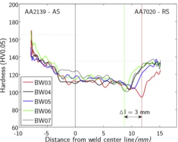
Vickers hardness measurements were conducted on both base ma-terials for references by taking the average value of 15 arbitrary mea-surements. The base material hardness is 165 HV0.05and 134 HV0.05for AA2139-T8 and AA7020-T651, respectively. Microhardness profiles along CWD performed at mid-thickness for the five conditions are presented inFig. 8. For all conditions, the hardness values progressively
Fig. 2. Pseudo-3D optical micrographs of base metals for: (a) AA2139-T8 and (b) AA7020-T651.
Fig. 3. Tensile specimen geometry used for both base materials and welded joints (all dimensions in mm).
decrease from the advancing side (AA2139) down to a plateau zone in the middle of the joint. Minimal values between 9 and 12 mm from the centerline of the joint are reported on the retreating side (AA7020), i.e. in the HAZ region, before going back to the base metal hardness. Even if significant microstructural (Fig. 5) and hardness differences are re-ported between the two base materials, the hardness in the nugget is relatively homogeneous and the interface between the two materials can only be identified using a microstructural criterion (see the absence of variation around the centerline of the weld (0 mm) inFig. 8). The average value inside the nugget (around 118 HV0.05) is practically not influenced by the welding conditions with a maximum variation of 20 HV0.05. No hardness drop was found on the AA2139 HAZ and except for the coldest welding condition (BW06) which exhibits slightly higher hardness values, all the hardness values in this region follow similar trends at ± 20 HV0.05. Things are different on the AA7020 side (RS) as the hardness distribution in the HAZ varies significantly and the posi-tion and the minimum values of the lowest hardness regions are a function of the welding conditions. Indeed, the hardness drop is found 12 mm from the weld center in the case of the hottest conditions (BW03), while the coldest condition (BW06) is found at 9 mm. The hottest condition reveals the lowest hardness value at 92 HV0.05while the other welding conditions display similar minimal hardness values 8 HV0.05higher.
Given the strong microstructural heterogeneities, a single hardness profile in mid-thickness is not sufficient to fully characterize the weld and a more global analysis using 2D hardness maps was performed. The
results are displayed in Fig. 9. The microstructural maps and the hardness maps correlate. The transition between the TMAZ + HAZ re-gion and the nugget can be easily distinguished on the AA2139 side (AS) due to a severe drop of hardness properties (ΔHV = 40 HV0.05 from 165 to 120) across this region, going from yellow/green to blue. Comparatively, this transition is less visible on the AA7020 side (RS) as the initial hardness of the base material is significantly lower and a continuous evolution of the hardness properties along CWD is to be noted.
The position of the minimal hardness was clearly associated with the HAZ on the AA7020 (RS) side. As observed on the filiation ofFig. 8
and onTable 3, the minimal hardness value levels are about 100 HV0.05 except for the hotter condition (BW03) for which a lower minimum hardness value is found around 92 HV0.05. If one defines the minimal hardness region (MHR) as the region of the material with hardness below 110 HV0.05, relatively straight bands can be identified on the hardness maps. They do correspond to any particular zone of the mi-crostructure maps and they move away from the joint center line as more heat is generated by the process. The advance speed is the process parameter that most affects the location of the MHR: the lower the advance speed is, the further away the MHR is from the nugget region. The closer to the centerline of the joint the MHR is, the more inclined and parallel to the TMAZ/nugget interface it becomes; far from the centerline of the joint, the MHR is mostly perpendicular to the sheet surface.
Increasing the advancing speed reduces the width of the MHR. The width of this MHR gets smaller as the MHR gets closer to the joint center, going from 2.7 mm when at a distance of 12 mm to a width of 0.84 mm for a distance of 9 mm. This significant decrease in width by a factor of 3.2 should improve the mechanical property of the joint by a notch strengthening effect; i.e., delaying necking in this region during tensile tests.
3.2.2. Tensile tests
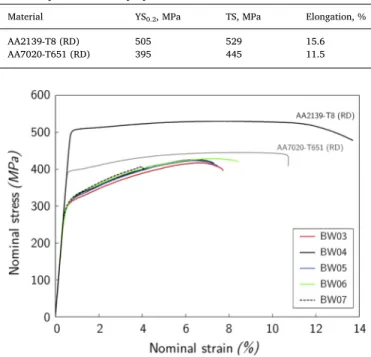
Tensile tests were performed to evaluate the macroscopic tensile properties of all the joint variants concerning the properties of the base metals. The tensile properties of both base metals are presented in
Table 4. AA2139-T8 demonstrates significantly stronger tensile prop-erties than AA7020-T651. Indeed, the 0.2% offset yield strength (YS0.2) and tensile strength (TS) are 28% and 19% higher in the RD direction
Fig. 5. Optical macrographs (CWD-ND plane) matrix for AA2139-T8 / AA7020-T651 configuration.
Fig. 6. Top view of weld surface with defect formation due to inappropriate welding parameters.
for the AA2139 than for the AA7020 in the same direction. While stronger, AA2139-T8 has also an interestingly higher ductility (+36%) than AA7020.
Fig. 10shows the stress-strain curves for the five welding conditions compared with both base metals in the rolling direction. The joint be-havior is close to base metal 7020-T651. The average tensile properties for each welding condition are listed inTable 5. The elastic domain is the same for all conditions while the plastic domain mainly differs for strains higher than 400 MPa. All samples show significant strain hard-ening compared to the base metals. Besides the BW07 condition, which failed suddenly at a relatively low strain of about 4%, the other four conditions display final elongations of about 7% and a curve typical of a necking behavior. Similar observations can be made concerning the necking strain, which reaches 3.5% for the BW07 condition and about 7% for the other four conditions. The efficiencies, defined as the ratio of the tensile properties of the joint to the base metal involved (using the weakest material in the case of dissimilar welding) are reported in
Table 5. Overall, the efficiencies are rather high going from 77 to 79% for the 0.2% offset yield strength and 88 to 96% for the ultimate tensile strength. Generally, increasing the welding speed tends to simulta-neously increase the yield and the ultimate tensile efficiency, whereas increasing the rotation speed reduces them.
The result dispersion is relatively low except for the highest rotation and advance speeds (condition BW07) which present a significant variability in the TS values and systematic low elongation-to-fracture. In fact, except for some samples in the BW07 condition, all joints sys-tematically failed in the HAZ on the AA7020 side (RS) between 7 and 13 mm from the centerline of the joint. For all samples that have failed in the HAZ, the MHR location matches with the maximum necking, with a slight offset due to the sample elongation during the tensile test.
Fig. 11 displays a clear example of such a behavior in the case of condition BW03. It can be noticed that the BW03 condition reaches the lowest hardness value and the largest MHR among all welding condi-tions. However, the BW03 weld is still fairly ductile regarding its
Fig. 7. BW03 welding condition: (a) optical detailed macrograph of the cross-section revealing the various zones inside the joint, (b) zooms on the different specific welding areas.
necking strain and elongation despite the drop of its TS. The remaining specimens in the BW07 condition failed in the nugget region close to the joint centerline.
3.2.3. Fracture surface analysis
Fracture surface analyses were performed for all processing condi-tions including base metals. All the joints failing in the HAZ of AA7020 had similar features to the ones displayed in Fig. 12a–c (condition BW03). A mixed mode fracture was found composed of dimples in-itiated from small intermetallic particles (dimples 10 µm in diameter) and transgranular regions revealing elongated grains. If compared to the fracture surface of the AA7020 base material (Fig. 12d–f) inter-esting differences can be found. The fracture surface of the AA7020 is mostly composed of relatively large dimples ( 20 µm in diameter) close to each other with only few elongated grain features. The sizes of the intermetallic particles found in the dimples are coarser in the base material than the ones found in the HAZ region. These fracture features are characteristic of highly deformed areas with localized stress
triaxiality. This is coherent with the fact that these minimum hardness regions are the locations of significant necking.
The fracture occurred in the nugget region of the joint for one sample of the fastest rotating condition (BW07). The fracture does not particularly follow this interface of the joint on the two thirds of the surface, but on the bottom of the weld, the fracture surface corresponds to the interface between the two materials (in green Fig. 13b). The fracture surface (Fig. 13c) reveals two regions along the WD: one with relatively homogeneous ductile features below the shoulder and related to the SANZ (Fig. 13d), and one deep enough in the material to be mainly controlled by the pin ability to mix the material (PANZ). In the latter region, periodic features that can be described as humps and hollows spaced by a distance equivalent to the advance per revolution of the tool can be observed. These periodic features can also be divided again into two zones, identified as zone I and zone II inFig. 13b. Zone I is located in the middle of the weld thickness and displays some regions with typical ductile fracture. This zone corresponds to a combination of both materials (part of the redFig. 13b) and large dimples (Fig. 13c) are found in humps, typical of the ductile behavior of AA7020. On the other hand, hollows correspond to the other material and no ductile features were found, even at high magnification (Fig. 13e). The alternation of these humps and hollows is quite similar to the alternative pattern found when cutting and polishing the sample in the WD-ND plane in the same location (Fig. 14b), justifying the fact that the joint interface is strong and that the crack propagates in both materials independently. Zone II, located in the lower part of the nugget, shows rough features and no sign of ductility at low magnification, even if some can be found locally at high magnification (Fig. 13h). This zone corresponds to the joint interface (greenFig. 13b) and documents the way the materials get mixed in that region. At the extreme bottom, an inclined foliation can be seen (Fig. 13i), documenting the lack of tool penetration. The spatial period between the coarse regularly spaced features is about 500 μm, which correspond to the linear advance for one tool revolution (R ratio = 0.55 mm.rev−1).
The periodic features corresponding to the various wavy patterns found in the nugget are well illustrated in both pictures ofFig. 14. A comparison betweenFigs. 13 and 14b is particularly interesting as an identical morphology is found where the SANZ consists only of AA7020 and the PANZ shows complex periodical features. The joint is defect free and the particular features observed on the lower part of the fracture surface reveal a weak material interface.
Fig. 8. Microhardness profiles at mid-thickness for the five welding conditions. Horizontal dot-lines show base material hardness while vertical green and red lines are the two extreme positions of the MHR function of the welding para-meters. (For interpretation of the references to color in this figure legend, the reader is referred to the web version of this article).
3.3. Mid-thickness thermal measurements around the MHRs for extreme conditions
Thermal profiles at mid-thickness during welding were performed for extreme conditions at each thermocouple location to see the effect of a given thermal cycle, and more precisely the effect of the peak temperatures and the exposure times, on the local mechanical proper-ties of the joints in the MHRs. Average temperature evolutions as a function of the time for thermocouple 5 (TC5), thermocouple 6 (TC6) and thermocouple 7 (TC7) at 10 mm, 12.5 mm and 15 mm from the center line, respectively, are shown for conditions BW03 and BW06 on
Fig. 15. It must be noted that the temporal offset between the curves has been removed to facilitate the analysis.
For a given thermocouple position, each peak value obtained for condition BW03 (hot condition) is 15–36 °C higher than that obtained for condition BW06 (cold condition). Table 6 summarizes the peak temperatures and the exposure times above 200 and 250 °C as measured for each thermocouple during welding for conditions BW03 and BW06. The exposure times obtained for condition BW03 are significantly higher than those obtained for condition BW06.
Since the distance of the MHR from the center line is different for each condition, the relative position of the thermocouple with respect to each MHR changes. For condition BW03, the MHR is between TC5 and TC6 whereas for BW06, the MHR is between TC5 and the center line of the weld. By extrapolation of the results presented inFig. 15and inTable 6, it is possible to estimate the thermal cycle undergone in the MHR for conditions BW03 (hot) and BW06 (cold). For the condition BW03, the MHR undergoes a peak temperature from 222 to 254 °C with exposure times from 3.7 to 0.9 s for 225 °C and from 4.3 to 5.9 s for 200 °C, respectively. For the condition BW06, the peak temperature is slightly higher than the one given by TC5, that is to say slightly higher than 234 °C and exposure times are slightly above 1 and 2.2 s for 225 °C
Table 3
Minimal hardness value in the MHR, width of the MHR (considering that the limit of the MHR corresponds to a hardness of 110 HV0.05) and position of the MHR from
the center line (at mid thickness) for various conditions.
Rotation speed, rev∙min−1/ advance speed,
mm∙min−1 Minimal hardness value(HV 0.05)
width of the MHR
(μm) position of the MHR from the center line(mm)
BW03 (R = 0.42) 600/250 92 2760 11.7 BW04 (R = 0.67) 600/400 101 1200 10.2 BW05 (R = 0.5) 800/400 101 1200 10.4 BW06 (R = 0.69) 800/550 99 840 8.7 BW07 (R = 0.55) 1000/550 97 960 9.2 Table 4
Room temperature tensile properties of the two base metals.
Material YS0.2, MPa TS, MPa Elongation, %
AA2139-T8 (RD) 505 529 15.6
AA7020-T651 (RD) 395 445 11.5
Fig. 10. Stress-strain curves for base metals and the five welding conditions. For each condition, one curve among the 3 performed was chosen (For inter-pretation of the references to color in this figure legend, the reader is referred to the web version of this article).
Table 5
Room temperature tensile properties and efficiencies (compared to AA7020-T651 RD) of welded samples for two different natural aging times. Average value represents average of test results of three samples.
Samples YS0.2, MPa TS, MPa Necking strain % Elongation, % Eff. RP0.2, % Eff. TS, % Eff. Elong., %
BW03 305± 0 417 ± 1 6.8± 0.1 7.2± 0.1 77 94 63
BW04 308± 0 425± 0 6.1± 0.1 6.4± 0.4 78 96 55
BW05 306 ± 0 422 ± 0 6.2± 0.3 6.6 ± 0.4 78 95 57
BW06 310 ± 1 427 ± 0 6.8± 0.4 7.2 ± 0.7 79 96 63
BW07 308 ± 1 389 ± 15 3.5± 0.5 3.7 ± 0.4 78 88 28
Fig. 11. Fracture analysis for the BW03 welding condition: correlation between the position of fracture and the microhardness map.
and 200 °C, respectively.
4. Discussion
The wide window of welding parameters tested on the dissimilar AA2139-T8 / AA7020-T651 welding configurations showed that similar microstructures were obtained in terms of morphology and hardness. Defect-free joints with a complex mixture that provides good mechan-ical bonding at the interface between the two materials have been
produced. Good mechanical results highlighted the great robustness of the FSW process in these conditions. Despite these relatively homo-geneous performances, the extreme welding condition (BW07 condi-tion) revealed a less predictable behavior and subsequent low me-chanical results related to the presence of a weak interface between the materials at the bottom of the joint.
To understand the possibilities to improve further the best tensile strength of the joints, the effects of the process heat on the character-istics of the MHR will be discussed below by looking at the thermal
Fig. 12. SEM fracture surface features at several magnifications. (a, b, c) welded joint (condition BW03): mixed mode fracture composed of dimples initiating from small intermetallic particles and transgranular fracture from elongated grains, (d, e, f) AA7020 base metal – dimples close to each other and only elongated grain features.
cycles seen in the nugget and in the HAZ.
The cycle in the nugget reaches temperatures higher than 260 °C resulting in a medium range of hardness levels (110–120 HV). Thus, the local temperatures are high enough to allow a complete dissolution of the initial precipitates followed by their precipitation thanks to the heat available in this region of the weld. These heat and precipitation cycles enable hardness levels close to the base metal hardness as reported by
Mahoney et al. (1998).
In the HAZ, the thermal cycle reaches a lower range of temperatures resulting in precipitation coarsening. This temperature range is called “critical temperature range” and result in MHR. According to the thermal results presented inFig. 15andTable 6, the critical tempera-ture range for this alloy can be determined: from 225 to 260 °C. In the literature,Ma and den Ouden (1999)identified a slightly higher critical temperature range in the case of AA7020-T6 arc welding (from 260 to 320 °C) whereas Mahoney et al. (1998) proposed a higher critical temperature range from 300 to 350 °C in a FSW study of AA7075-T651. These higher critical temperature ranges could be due to a shorter
exposure time. In fact, the MHR is not only governed by a range of temperatures but also by the exposure time to these temperatures. The thermal cycles decreasing the hardness vary from one welding condi-tion to another as the features of the welds change, such as the distance from the welding line to the MHR or the width of the MHR, which also change from one condition to another.
As the advancing speed increases, the MHR approaches the center line and so does the critical temperature range. This is due to the fact that, as the advancing speed increases, for a given time period, the same amount of heat is spread over a larger material surface. The resulting cooling rate of the weld is higher as the base material acts as a heat sink, and the critical temperature range moves closer to the center line of the weld. The advance speed plays the leading role in the heat input; in comparison, the rotating speed, and therefore the speed ratio R, do not have any significant effect.
In addition to their positions with respect to the welding line, the MHRs differ from one condition to another: their minimum values and their widths vary. Based on the thermal measurements performed, their
Fig. 13. Fracture on a BW07 sample failed in nugget: (a) Position of area “(c)”, (b) Cross weld section with green dotted line for the interfacial fracture and red dotted line for the non-interfacial fracture, (c) Fracture surface revealing homogeneous SANZ and periodic PANZ. In PANZ, two regions can be found according to surface morphology (zones I and II), (d, e, f, g and h) Zoom of various areas on the fracture surface in (c).
characteristics are directly dependent on the time of exposure to the critical temperature range. The higher the exposure time, the lower the minimum value reached and the wider the MHR and vice versa. As a result, the BW03 (hot) condition has the widest MHR and the lowest minimum hardness values compared to the other conditions. Conversely, condition BW06 (cold) has the lowest MHR and the highest minimum hardness value. Interestingly, these MHR characteristics are not influenced by the peak. As thermal measurements have been made only for conditions BW03 and BW06, the conditions that control the MHR characteristics cannot be verified for all conditions. However, it can be observed onFig. 9andTable 3that the width of the MHR de-creases as the advancing speed inde-creases with a minor contribution of the rotation speed. In fact, as the advancing speed increases, the welding process is faster and the exposure time to the critical
temperature range decreases; thus, decreasing the width of the MHR. However, there is no specific relationship between the width of the MHRs and the speed ratios R.
To summarize, the thermal measurements show that reaching a temperature that is within the critical temperature range, i.e. from 225 to 260 °C, generates the MHR while the exposure time influences the width and the minimum value of the MHR. The position of the MHR, as well as the exposure time, are mainly influenced by the advance speed of the tool which therefore controls the heat input.
The fact that the width of the MHR is significantly reduced when the temperature of the weld decreases is also an interesting trend as re-ducing the width of the low MHR may improve the mechanical property by notch strengthening. Indeed, reducing the width of the MHR may reduce the stress triaxiality in this region during the tensile test and could increase the tensile properties of the joints. However, the me-chanical results in Fig. 10 and Table 5 show that the mechanical properties do not significantly change with the MHR widths. This suggests that the width of the MHR obtained in the present work may not be small enough to benefit from this mechanical strengthening. Targeting lower heat exposure during the welding process by using faster advancing speeds for instance may further improve the me-chanical properties of the joints. This could improve the meme-chanical properties of the joints produced in two ways: by reducing the width of the MHR further or/and increasing the lower hardness value in the MHR. However, the excessive increase of the speeds leads to the in-stability of the process that produces defects in the welded joint. In this case, a lack of cohesion at the interface between the two materials in the nugget, itself due to a lack of metallurgical bonding, can be iden-tified for the high speed condition (BW07) and leads to a fracture at the same place. Therefore, the elongation has been halved.
5. Conclusions
•
The welding parameters have globally no influence on the tensile behavior. A satisfactory minimum efficiency of 88% regarding the TS and 77% regarding the 0.2% offset yield strength is reached.•
In the higher advancing and rotation speed condition, a weakness regarding TS and elongation was found; this was attributed to in-sufficient mixing of the material at the root of the joint due to a too small pin size.Fig. 14. (a) Bottom (CWD-WD) and (b) Longitudinal (WD-ND) views of the BW07 welding condition showing the patterns obtained etching. Darker ma-terial corresponds to AA2139 and light grey mama-terial to AA7020.
Fig. 15. Average mid-thickness thermal measurements measured during welding around the MHRs with locations of the thermocouples: (a) Condition BW03 (hot), (b) Condition BW06 (cold).
•
The highest the advancing speed is, the smaller the width of the MHR is and the closer it is to the nugget region. The exposure time to the critical temperature ranges is also mostly dependent on the advancing speed suggesting that with the present tool it is the main parameter to control the heat input.•
The regions whose hardness is below 110 HV0.05are located in the HAZ of the AA7020 side for all conditions. The origin of this weak zone was primarily linked to the precipitates coarsening in the base metal due to an exposure to temperatures in the range from 225 to 260 °C. The exposure time to this critical temperature range could also play a role in controlling the hardness decrease and the width of the MHR.•
The fractures in the MHR on the AA7020 side are similar for all joints (dimples and transgranular fracture). In the higher advancing and rotation speed condition, specimens failed in the nugget most likely because of a lack of cohesion at the interface between the two materials in this area. This lack of cohesion is certainly due to an instability of the process for high welding speed and a lack of ma-terial mixing in this region which leads to a lack of metallurgical bonding. It could be avoided by changing the tool geometry and increasing the length of the pin for higher welding speed conditions.Data availability
The raw and processed data required to reproduce these findings are available to download from Mendeley Data:https://doi.org/10.17632/ 4gc86ddp6s.2.
Acknowledgements
The authors are particularly grateful to the Ministry of Economy, Science and Innovation from Quebec government for the grant attrib-uted via the Research Support Program (PSR). This work was part of a research program supported by the Aluminum Research Centre -REGAL. A part of this work was also supported by the financial support of the French government defense agency, Direction Générale de l’Armement (DGA).
References
Ahmed, M.M.Z., Wynne, B.P., Rainforth, W.M., Addison, A., Martin, J.P., Threadgill, P.L., 2019. Effect of tool geometry and heat input on the hardness, grain structure, and crystallographic texture of thick-section friction stir-welded aluminium. Metall. Mater. Trans. A Phys. Metall. Mater. Sci. 50, 271–284.https://doi.org/10.1007/ s11661-018-4996-2.
Al-Obaisi, A.M., El-Danaf, E.A., Ragab, A.E., Soliman, M.S., 2016. Precipitation hardening and statistical modeling of the aging parameters and alloy compositions in Al-Cu-Mg-Ag alloys. J. Mater. Eng. Perform. 25, 2432–2444. https://doi.org/10.1007/s11665-016-2076-6.
Avettand-Fenoel, M.-N., Simar, A., 2016. A review about Friction stir welding of metal matrix composites. Mater. Charact. 120, 1–17.https://doi.org/10.1016/j.matchar. 2016.07.010.
Cavaliere, P., Nobile, R., Panella, F.W., Squillace, A., 2006. Mechanical and micro-structural behaviour of 2024/7075 aluminium alloy sheets joined by friction stir welding. Int. J. Mach. Tools Manuf. 46, 588–594.https://doi.org/10.1016/j. ijmachtools.2005.07.010.
da Silva, A.A.M., Arruti, E., Janeiro, G., Aldanondo, E., Alvarez, P., Echeverria, A., 2011. Material flow and mechanical behaviour of dissimilar AA2024-T3 and AA7075-T6
aluminium alloys friction stir welds. Mater. Des. 32, 2021–2027.https://doi.org/10. 1016/j.matdes.2010.11.059.
Eberl, I., Hantrais, C., Ehrtsrom, J.-C., Nardin, C., 2010. Friction stir welding dissimilar alloys for tailoring properties of aerospace parts. Sci. Technol. Weld. Join. 15, 699–705.https://doi.org/10.1179/136217110X12813393169499.
Firouzdor, V., Kou, S., 2010. Al-to-Mg friction stir welding: effect of positions of Al and Mg with respect to the welding tool. Metall. Mater. Trans. A 19, 672–684. Gaafer, A.M., Mahmoud, T.S., Mansour, E.H., 2010. Microstructural and mechanical
characteristics of AA7020-O Al plates joined by friction stir welding. Mater. Sci. Eng. A 527, 7424–7429.https://doi.org/10.1016/j.msea.2010.08.040.
Giraud, L., Robe, H., Claudin, C., Desrayaud, C., Bocher, P., Feulvarch, E., 2016. Investigation into the dissimilar friction stir welding of AA7020-T651 and AA6060-T6. J. Mater. Process. Technol. 235, 220–230.https://doi.org/10.1016/j.jmatprotec. 2016.04.020.
Grujicic, M., Arakere, G., Yen, C.-F., Cheeseman, B.A., 2011. Computational investigation of hardness evolution during friction-stir welding of AA5083 and AA2139 aluminum alloys. J. Mater. Eng. Perform. 20, 1097–1108. https://doi.org/10.1007/s11665-010-9741-y.
Hartmann, M., Böhm, S., Schüddekopf, S., Hartmann, M., Böhm, S., Schüddekopf, S., 2014. Influence of surface roughness of tools on the friction stir welding process. J. Korean Weld. Join. Soc. 32 (6), 12.https://doi.org/10.5781/JWJ.2014.32.6.22. Heidarzadeh, A., Barenji, R.V., Esmaily, M., Ilkhichi, A.R., 2015. Tensile properties of
friction stir welds of AA 7020 aluminum alloy. Trans. Indian Inst. Met. 68, 757–767.
https://doi.org/10.1007/s12666-014-0508-2.
Huang, Y., Xie, Y., Meng, X., Lv, Z., Cao, J., 2018. Numerical design of high depth-to-width ratio friction stir welding. J. Mater. Process. Technol. 252, 233–241.https:// doi.org/10.1016/j.jmatprotec.2017.09.029.
Jain, R., Kumari, K., Kesharwani, R.K., Kumar, S., Pal, S.K., Singh, S.B., Panda, S.K., Samantaray, A.K., 2015. Friction stir welding: Scope and recent development. Modern Manufacturing, Materials Forming, Machining and Tribology. Springer International Publishing, Cham, pp. 179–229. https://doi.org/10.1007/978-3-319-20152-8_6.
Jha, A.K., Narayanan, P.R., Diwakar, V., Kumar, K.S., Mittal, M.C., 2004. Metallurgical analysis of cracked aluminum alloy (AFNOR 7020) components used in satellite launch vehicles. Eng. Fail. Anal. 11, 463–474.https://doi.org/10.1016/j.engfailanal. 2003.05.016.
Kamp, N., Sullivan, A., Robson, J.D., 2007. Modelling of friction stir welding of 7xxx aluminium alloys. Mater. Sci. Eng. A 466, 246–255.https://doi.org/10.1016/j.msea. 2007.02.070.
Khodir, S.A., Shibayanagi, T., 2008. Friction stir welding of dissimilar AA2024 and AA7075 aluminum alloys. Mater. Sci. Eng. B Solid-State Mater. Adv. Technol. 148, 82–87.https://doi.org/10.1016/j.mseb.2007.09.024.
Krishnan, K.N., 2002. On the formation of onion rings in friction stir welds. Mater. Sci. Eng. A 327, 246–251.https://doi.org/10.1016/S0921-5093(01)01474-5. Kumar, M., Sotirov, N., Chimani, C.M., 2014. Investigations on warm forming of
AW-7020-T6 alloy sheet. J. Mater. Process. Technol. 214, 1769–1776.https://doi.org/10. 1016/j.jmatprotec.2014.03.024.
Lach, C.L., Domack, M.S., 2003. Characterization of Al-Cu-Mg-Ag Alloy RX 226-T8 Plate. Luo, C., Li, X., Song, D., Zhou, N., Li, Y., Qi, W., 2016. Microstructure evolution and
mechanical properties of friction stir welded dissimilar joints of Zn-Gd and Mg-Al-Zn alloys. Mater. Sci. Eng. A 664, 103–113.https://doi.org/10.1016/j.msea.2016. 03.117.
Ma, T., den Ouden, G., 1999. Softening behaviour of Al–Zn–Mg alloys due to welding. Mater. Sci. Eng. A 266, 198–204.https://doi.org/10.1016/S0921-5093(99)00020-9. Mahoney, M.W., Rhodes, C.G., Flintoff, J.G., Bingel, W.H., Spurling, R.A., 1998.
Properties of friction-stir-welded 7075 T651 aluminum. Metall. Mater. Trans. A 29, 1955–1964.https://doi.org/10.1007/s11661-998-0021-5.
Masoumi Khalilabad, M., Zedan, Y., Texier, D., Jahazi, M., Bocher, P., 2018. Effect of tool geometry and welding speed on mechanical properties of dissimilar AA2198–AA2024 FSWed joint. J. Manuf. Process. 34, 86–95.https://doi.org/10.1016/j.jmapro.2018. 05.030.
Mishra, R.S., Komarasamy, M., 2016. Chapter 2 - physical metallurgy of 7XXX alloys. Friction Stir Welding of High Strength 7XXX Aluminum Alloys. pp. 5–14 Butterworth-Heinemann.
Mishra, R.S., De, P.S., Kumar, N., 2014. Chapter 1 - introduction. Friction Stir Welding and Processing: Science and Engineering. Springer International Publishing, pp. 1–11.
Noh, S., Ando, M., Tanigawa, H., Fujii, H., Kimura, A., 2016. Friction stir welding of F82H steel for fusion applications. J. Nucl. Mater. 478, 1–6.https://doi.org/10.1016/j. jnucmat.2016.05.028.
Prisco, U., Squillace, A., Astarita, A., Velotti, C., 2013. Influence of welding parameters
Table 6
Average peak temperatures measured during welding around the MHRs for conditions BW03 (hot) and BW06 (cold).
Distance from the center line (mm) BW03, hot (600 rev. min−1/ 250 mm.min-1, R = 0.42 mm.rev-1) BW06, cold (800 rev. min−1/ 550 mm.min−1, R = 0.69 mm.rev−1)
Peak temperature (°C) Exposure time above (s) Peak temperature (°C) Exposure time above (s)
200 °C 225 °C 200 °C 225 °C
TC 5 10 254 5.9 3.7 234 2.2 1.0
TC 6 12.5 227 4.3 0.9 186 – –
and post-weld aging on tensile properties and fracture location of AA2139-T351 friction-stir-welded joints. Mater. Res. 16, 1106–1112.https://doi.org/10.1590/ S1516-14392013005000099.
Radisavljevic, I., Zivkovic, A., Radovic, N., Grabulov, V., 2013. Influence of FSW para-meters on formation quality and mechanical properties of Al 2024-T351 butt welded joints. Trans. Nonferrous Met. Soc. China 23, 3525–3539.https://doi.org/10.1016/ S1003-6326(13)62897-6.
Sree Sabari, S., Malarvizhi, S., Balasubramanian, V., 2016. Characteristics of FSW and UWFSW joints of AA2519-T87 aluminium alloy: effect of tool rotation speed. J. Manuf. Process. 22, 278–289.https://doi.org/10.1016/j.jmapro.2016.03.014. Sun, T., Roy, M.J., Strong, D., Withers, P.J., Prangnell, P.B., 2017. Comparison of residual
stress distributions in conventional and stationary shoulder high-strength aluminum alloy friction stir welds. J. Mater. Process. Technol. 242, 92–100.https://doi.org/10. 1016/j.jmatprotec.2016.11.015.
Texier, D., Zedan, Y., Amoros, T., Feulvarch, E., Stinville, J.-C., Bocher, P., 2016.
Near-surface mechanical heterogeneities in a dissimilar aluminum alloys friction stir welded joint. Mater. Des. 108, 217–229.https://doi.org/10.1016/j.matdes.2016.06. 091.
Velotti, C., Astarita, A., Buonadonna, P., Dionoro, G., Langella, A., Paradiso, V., Prisco, U., Scherillo, F., Squillace, A., Tronci, A., 2013. FSW of AA 2139 plates: Influence of the temper state on the mechanical properties. Key Eng. Mater. 554–557, 1065–1074.
https://doi.org/10.4028/www.scientific.net/KEM.554-557.1065.
Wu, H., Chen, Y.C., Strong, D., Prangnell, P., 2015. Stationary shoulder FSW for joining high strength aluminum alloys. J. Mater. Process. Technol. 221, 187–196.https:// doi.org/10.1016/j.jmatprotec.2015.02.015.
Yan, Z., Liu, X., Fang, H., 2016. Effect of sheet configuration on microstructure and mechanical behaviors of dissimilar Al–Mg–Si/Al–Zn–Mg aluminum alloys friction stir welding joints. J. Mater. Sci. Technol. 32, 1378–1385.https://doi.org/10.1016/j. jmst.2016.10.011.