Science Arts & Métiers (SAM)
is an open access repository that collects the work of Arts et Métiers Institute of
Technology researchers and makes it freely available over the web where possible.
This is an author-deposited version published in:
https://sam.ensam.eu
Handle ID: .
http://hdl.handle.net/10985/15465
To cite this version :
Angel SAPENA-BAÑÓ, Francisco CHINESTA, Jose Vicente AGUADO, Domenico
BORZACCHIELLO, Rubén PUCHE-PANADERO - Induction machine model with finite element
accuracy for condition monitoring running in real time using hardware in the loop system
-International Journal of Electrical Power and Energy Systems - Vol. 111, p.315-324 - 2019
Any correspondence concerning this service should be sent to the repository
Administrator :
[email protected]
Induction machine model with finite element accuracy for condition
monitoring running in real time using hardware in the loop system
A. Sapena-Bano
⁎,1, F. Chinesta
2, M. Pineda-Sanchez
1, J.V. Aguado
3, D. Borzacchiello
3,
R. Puche-Panadero
1Institute for Energy Engineering, Universitat Politècnica de València, Camino. de Vera s/n, 46022 Valencia, Spain
A R T I C L E I N F O Keywords:
Fault diagnosis
Hierarchical Lagrange interpolation Induction machines
Model order reduction Sparse subspace learning
A B S T R A C T
Most industrial processes are run by induction machines (IMs). Condition monitoring of IM assures their ctinuity of service, and it may avoid highly costly breakdowns. Among the methods for condition monitoring, on-line motor current signature analysis is being attracting a rising interest, because it is non-invasive, and it can identify a wide variety of faults at early stage. To favour the development of on-line fault diagnosis techniques, it is necessary to have real-time currents with which test the new techniques and devices. Models running in real time in hardware-in-the-loop (HIL) simulators are a suitable alternative to balance the drawbacks of test benches (costly, limited machines, faults and working conditions). These models must be accurate enough to reflect the effects of a fault and they must be running in real time. A promising technique based on the equivalent circuit parameters calculation of IM by finite element analysis (FEA) is attracting a rising interest due to its reliability, performance and the possibility of being run in a HIL. Nevertheless, prior to running in a HIL, it is necessary to compute the IM parameters using FEA, which requires long simulation times and high computing resources. Consequently, covering a whole range of degrees of a giving fault could be unaffordable. What is proposed in this paper is to apply the sparse subspace learning (SSL) in combination with the hierarchical Lagrangian inter-polation (HLI) to obtain the parametric solutions of the faulty IM model that cover the whole range of severity of a given fault, with a reduced number of FEA simulations. By means of this approach it is possible not only to boost the computation speed but also to achieve a significant reduction of memory requirements while retaining reasonable accuracy compared to traditional FEA, so enabling the real-time simulation of predictive models.
1. Introduction
Rotating electrical machines are critical components not only in the industry (working as a motors) but also in the electrical power gen-eration (working as generators). The electric machines are the driving force of the industry. Indeed, IMs account for a major fraction ( 64%) of total industrial energy uses[1]. Among all types of electrical ma-chines, squirrel-cage IMs have a prevalence in industry applications due to their low cost, robustness and low maintenance requirements, which are key issues in harsh industrial environments. Despite their robustness IMs are not free from suffering faults that can lead to unexpected fail-ures and production breakdowns, causing large economic losses [2]. Consequently, the detection of faults at early stage is crucial to adjust
the maintenance plans, allowing a faster reparation and avoiding un-expected shut-downs of the production line[3].
In this context, a wide variety of magnitudes have been used for the purpose of condition monitoring of the IMs such as thermal monitoring, either measuring or estimating the temperature or through the analysis of thermal images [4], the magnetic flux monitoring [5], vibration
[6,7], noise[7], partial discharges[8], air-gap torque monitoring[9], etc. However, these magnitudes have several drawbacks such as the use of expensive sensors, which most times cannot be installed and used in large machines for fault diagnosis. Besides, it is not easy to detect all types of faults using these magnitudes[10].
On the other hand, many recently published research works propose the use of the stator current for condition monitoring of the IMs.
⁎Corresponding author.
E-mail addresses:[email protected](A. Sapena-Bano),[email protected](F. Chinesta),[email protected](M. Pineda-Sanchez), [email protected](J.V. Aguado),[email protected](D. Borzacchiello),[email protected](R. Puche-Panadero).
1Institute for Energy Engineering, Universitat Politècnica de València, Spain. 2École nationale supérieure des arts et métiers, Paris, France.
3Ecole Centrale Nantes, France.
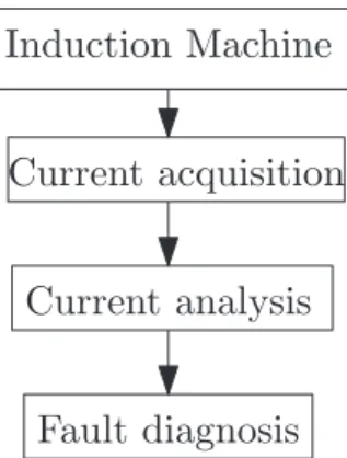
Indeed, motor 24 current signature analysis (MCSA) has become a no-table approach for IM fault diagnosis, because the currents of a faulty IM contain frequency components which can be related to both me-chanical faults (rolling bearings, eccentricity) and electric and magnetic asymmetries (stator winding short-circuits, rotor broken bars)[10]. Besides, MCSA is non-invasive, and it has low hardware (just a clip-on Hall effect probe) and software requirements [11–13] (Fourier Ana-lysis).Fig. 1shows the general diagram procedure for condition mon-itoring of IM through the analysis of the current.
However, MCSA faces some practical difficulties that are still lim-iting its industrial implementation. First, the rough industrial environ-ment in which the machine operates, the electromagnetic noise, the mechanical coupling with the load, the air ducts of the machine, etc. can induce harmonic components in the stator current, not related to the fault, which may lead to false positives [14,15]. Second, MCSA relies on failure thresholds, but there is not a clear line that determi-nates the presence or absence and the severity of a given fault, because they can be machine dependent. Finally, the working conditions can affect the diagnostic procedure. Most machines work under non-sta-tionary regimes, which require complex fault diagnostic algorithms that can operate in the joint time-frequency domain, where the FFT cannot be used to identify fault-related peaks in the current spectrum[16–18]. Due to the critical role of induction machines in industries and power generation plants, there is a need to address these problems in order to increase the reliability of condition monitoring systems. The main goal is to detect the faults at a very early stage, while reducing missed and false alarms rates [19]. To achieve this objective the use of the artificial in-telligence to develop expert systems based on support vector machines (SVM)[20]or artificial neural networks (ANN)[21]have been proposed in the technical literature. Besides, there is a rising interest in developing non-invasive, on-line assessment of the motor condition that can continuously monitor, detect and identify motor faults in an early stage, before an un-expected shut-down of the production line[2]. It implies the development of fault diagnostic algorithms running in embedded devices, such as digital signal processors (DSPs) [12,22], field programmable gate arrays FPGAs
[23]or even in the variable speed drive (VSD) that controls the machine. And these diagnostic systems must be able to perform on-line condition monitoring[9,24]of IMs, under different working conditions[25], both in steady state and in transient regime, as well as under non-stationary working conditions.
The development and training of these expert systems requires a large number of sampled currents, which should be obtained from several motors, with different types and severity degrees of a given fault or even with simultaneous faults. Besides, to enable the development and test of fault diagnosis techniques running in embedded devices, these signals must be produced and sampled in real-time. The main drawback is the access to many induction machines to fulfill the re-quirements aforementioned. It requires cooperation with industry, but the number of faulty induction machines that could be running in the industry is very limited.
Another option for obtaining faulty currents is to use IMs installed in laboratory test benches. Despite being necessary for the last stage of development (to test the fault diagnosis techniques, the devices, the expert systems, etc), this option not only has the same problems as with IMs installed in the industry, such as the limitation to those IMs available in the laboratory, but it has added drawbacks, such as the costs, the needs of a large number of destructive tests, the added challenge to obtain different degrees of failure or even simultaneous faults, and the difficulty to vary parameters that modify the working conditions, among others.
Alternatively, the use of accurate models of the faulty IM would have a major impact in the fault diagnosis field. These models aim at reducing the number of destructive tests needed to validate new diag-nostic techniques, to test fault diagdiag-nostic techniques implemented in embedded devices, to train expert systems to classify IM faults[26]or to develop vector classifiers[27]. These models are also very helpful for a better understanding of the observed phenomena[28]and to define and compare different fault indexes[29]which can lead to the devel-opment of new diagnostic techniques. In the next subsections, the most recent advances in the development of faulty IM models are reviewed, as well as the bottlenecks in their practical use.
1.1. Faulty induction motor models
Several models of rotating electrical machines have been proposed in the technical literature. The well-known dynamic d-q model[30,31]
is simple enough to be implemented in fast HIL[32]. However, this model cannot be used for fault diagnosis purposes, because it neglects the harmonic contents generated by phase windings, and is unable to model the torque pulsations that appear in the machine shaft due to the interaction between time and space harmonics[33]. The challenge is to perform the machine condition monitoring under conditions in which both the phase currents and the phase voltages are not sinusoidal and torque pulsations are present on the shaft[34]. Therefore, the machine model for diagnostic purposes should include the effect of spatial har-monics, as in the model presented in[35]. Afterwards, other analytical approaches have been proposed such as the multiple coupled circuit (MCC) model[36], the winding function approach (WFA) [37], the Concordia transformations[38], the use of natural variables[39], the voltage-behind-reactance formulation [40,41], or the magnetic equivalent circuit (MEC)[32,42]. However, these analytical approaches cannot properly model non-linearities and non-ideal conditions, as re-quired for an accurate motor model valid for diagnostic purposes.
The use of finite elements method (FEM) for modelling highly increases the accuracy in machine simulation [43], but it requires a significant computational capacity. Despite the improvements on computer speed, the computational effort required to complete FEM evaluation is significant even with modern processing power computers[44]. Indeed, it requires long simulation times, from minutes to days in case of highly asymmetrical faults such as mixed eccentricity or rotor broken bars. The savings in computational effort are crucial in situations where a large number of stu-dies are required, such as in fault diagnosis, optimization of the motor control, expert systems training, etc.
Therefore, some authors have proposed alternatives such as the use of advanced analytical models [45,46] or combined FEM-analytical model
[47]to reduce the computation time of FEM models. They are based on the equivalent circuit parameters calculation of IM by FEM models[48,49]. The resulting analytical model has a reliability similar to a FEM model and it can run in real-time in HIL, which is a need for fault diagnosis. Additionally, the test of fault diagnosis techniques requires a set of signals that cover a wide range of scenarios such as different degrees of a fault or combination of several types of faults. But the evaluation of each new scenario (fault con-ditions) can become extremely expensive, because it requires the full si-mulation of the new FEM model with their corresponding long sisi-mulation times and high computational effort. These issues are definitely limiting its implementation.
1.2. Contributions and paper structure
From the discussion in the previous sections, it can be concluded that the use of accurate IM models would have a major impact in the fault diagnosis field. On the other hand, the main bottleneck is that fault diagnosis requires accurate models of the faulty IMs (covering a wide range of scenarios: machine, type and degrees of a fault) running in real time. But both requirements are in conflict. The most accurate methods, such as those based on FEM, require a high computing power and long running times. On the contrary, HIL systems are able to run machine models in real time[32,50], but they are limited to analytical models. A promising technique is to use equivalent circuits of IM whose parameters are obtained through FEM simulations[48,49], due to its reliability, performance and the possibility of running it in a HIL. Nevertheless, each new scenario requires a complete FEM analysis, which is extremely costly and could be unaffordable.
In the technical literature, especially in computational mathematics, many methods have been developed to alleviate this problem. For example, design of experiment (DOE), widely used in the industry, reduces the number of simulations based on a series of statistical indicators[51]. An alternative approach is based on reduced order modelling (ROM) methods
[52–54], with both a-priori and a-posteriori ROM strategies. Since most of the time is consumed in multi-query simulation, ROM methods are designed so as to reduce the computational complexity of evaluating a given con-figuration [55]. However, the main drawback of these projection-based ROM is that not only the solution must be reducible but also the problem formulation must have a proper structure.
To address this limitation, recently, the SSL has been proposed in
[55]. The SSL is able to produce parametric solutions based only on the output of a deterministic solver to which the parameters are fed as input in a multi-level interpolation framework. More specifically, the SSL uses hierarchical collocation to compute a low-rank representation of the parametric solution. With this rationale, the predictions obtained from the hierarchical interpolation are used as an optimal initial guess to initialize the deterministic solver at a new sampling point. If this guess is good enough the solver will not even run. Therefore, the time re-quirements are drastically reduced. However, for fault diagnosis pur-poses, this approach still requires a full FEM analysis with its corre-sponding computational costs (memory resources and computing power) and long simulation times.
In an attempt to overcome these limitations, this paper proposes to apply the SSL method to obtain the parametric solutions of the faulty IM model that cover the whole range of severity of a given fault with a reduced number of simulations. In this paper the proposed method is applied to the case of static eccentricity fault, but the same procedure could be applied to the simulation of other types of faults such as rotor asymmetries, inter-turn stator short-circuit fault, other types of eccen-tricity (dynamic, mixed) etc. As a novelty, in this paper, the SSL is used to obtain the parametric solutions instead of the predictions to initialize
the deterministic model at a new sampling point as in[55]. It results in an impressive reduction of time and computing requirements while keeping a great accuracy.
The paper is structured as follows. InSection 2the equations that define a parametric model of a IM and the main drawbacks to compute the parameters are introduced. InSection 3the methodology used to compute the parametric solutions of the fault IM model is presented. The case of study introduced inSection 4is used to illustrate the SSL and the HLI method proposed in this paper, which is explained deeply inSection 5. Subsequently, inSection 6, the model is implemented in the HIL and the results, in terms of fault diagnosis purposes, are shown. Finally, the main conclusions of this work are presented inSection 7.
2. System equations
A general IM with m stator and n rotor phases can be modelled with the following equations[56,57]:
= + U R I s t [ ]s [ ][ ]s s d[ ]/d (1) = + U R I r t [ ]r [ ][ ]r r d[ ]/d (2) = L I + L I [ ]s [ ss][ ]s [ sr][ ]r (3) = L I + L I [ ]r [ sr] [ ]T s [ rr][ ]r (4) = … U u u u [ ]s [ ,s1 s2, , sm]T (5) = … U u u u [ ]r [ r1, r2, , rn]T (6) = … I i i i [ ]s [ ,s1 s2, ,sm]T (7) = … I i i i [ ]r [ ,r1 r2, , ]rnT (8)
where U[ ]is the phase voltages matrix, I[] is the phase currents matrix, R
[ ]is the resistances matrix, [ ] is the flux linkages matrix and L[ ]is the inductances matrix. Subscripts s andrare used for the stator and for the rotor, respectively. The mechanical equations are:
= T [ ]I d[L ] I d [ ] e sT sr r (9) = + T T J t B t d d d d e Load 2 2 (10)
where Te is the electromechanical torque generated by the machine,
TLoadis the mechanical load torque, J is the inertia moment,B is the
friction coefficient and is the rotor position.
The system Eqs.(1)–(10)must be solved using a simulink model to run in real time in the HIL. In this case, the model has been divided into two subsystems as can be seen inFig. 2. The subsystem sc_user_interface is used to modify set points and to monitor the results while the si-mulation is running. For instance, to cover a wide variety of industrial cases, the user could select the type of connection of the IM between
direct on-line (DOL) or through a VSD (with the usual open/close loop controls). Once the connection is chosen and the real-time simulation is running the user can modify, in real-time, different parameters of the power supply such as the voltage and/or the frequency (or reference speed depending on the VSD control selected). The user can, also, modify the load torque during the real-time simulation or even define torque profiles to simulate industrial processes. Moreover, from this subsystem, the user can monitor the main results of the real-time si-mulation such as the stator currents, the torque generated and the speed, and save them in a file for post-processing purposes. On the other hand, the subsystem called sm_computation is used to create the de-tailed model that solves the system Eqs.(1)–(10), as shown inFig. 3.
In the schema implemented inFig. 3the stator and rotor quantities have been grouped, allowing the system Eqs.(1)–(10)to be expressed as: = + U U R R I I t L L L L I I 0 0 d d s r s r s r ss sr rs rr s r (11) = T I I L L L L I I 1 2[ ] d d e s r ss sr rs rr s r (12)
where L[ ]ss contains the mutual inductances between the stator phases
and their leakage inductances, L[ rr] contains the mutual rotor in-ductances between rotor phases and their leakage inin-ductances and L[ ]sr
contains the mutual inductances between the stator and rotor phases. In case of a faulty IM all of these inductances depend on the rotor position. Therefore, to solve(11) and (12)the self and mutual inductances must be computed for each rotor position. Moreover, due to the presence of derivatives in(12)these inductances must be computed with high ac-curacy, specially, if different faulty conditions need to be detected and identified in a reliable way. As said before, in this paper, the elements of matrices L[ ]ss, L[ rr], L[ ]sr are computed using FEM software to obtain a
good accuracy but focusing on the reduction of the time and computing resources required in this process.
3. Methodology
The accuracy of FEA allows to create IM models that consider the non-uniform air-gap due to stator and rotor slots. Besides, FEA con-siders other possibles asymmetries produced due to IM faults such as eccentricity, rotor broken bars or inter-turn short circuits. In case of a faulty machine, usual simplifications that speed up the FEA, like sym-metry and anti-symsym-metry boundary conditions, can no longer be ap-plied. Hence, performing a single simulation is more time-consuming than in the case of healthy machines, because the whole geometry must be taken into account. Besides, a considerable number of simulations is required to compute the inductance matrix in every possible scenario that is likely to occur in the life cycle of an IM.
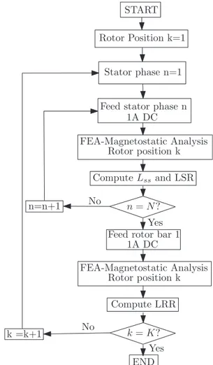
The diagram ofFig. 4shows the required steps to compute the in-ductances matrix of a faulty motor. For each rotor position the machine model is built in the FEA software. After that, each stator phase is fed with an unit direct current, the FEA magneto-static simulation is per-formed as shown inFig. 5and the stator-stator,Lss, and stator-rotor,Lsr,
inductances for the corresponding rotor position are computed by in-tegration of the magnetic potential in the areas occupied by the dif-ferent windings of the stator phase or the rotor bars. Finally, a rotor phase (the loop formed by two consecutive rotor bars) is also fed by an unit direct current to compute the rotor-rotor,Lrr, inductances for the
corresponding rotor position. The iteration process continues until the inductances matrix is computed for each rotor position. It becomes clear that, due to the complexity of the geometrical resolution, the large number of configurations that must be evaluated implies a significant cost in terms of time and computational resources.
4. Case of study
To test embedded equipment and fault diagnosis techniques it is required to acquire real-time signals to cover a wide range of scenarios. That means that it is necessary to obtain simulations with different
working conditions as well as types and severity of faults.
This paper is focussed in showing the benefits of SSL and the HLI in order to reduce the computational and time requirements to compute
the inductances matrix. This allows simultaneously to create parametric models which can run in real time simulators (HIL) and to consider different types and severity degrees of a given fault. Such approach would be unaffordable using a test bench or even using FEA models, due to the fact that all the steps shown inFig. 4are required for each degree of a given fault.
In this case, these benefits are illustrated using the model of a IM which main characteristics are depicted inTable 1, considering only the static eccentricity fault. The goal is to obtain the inductance matrix for each degree of fault severity, that is, from healthy conditions, where eccentricity is null, up to the maximum degree of static eccentricity. For the simulated machine, this implies a maximum displacement of the rotor rotation centre (considering the rotor perfectly cylindrical) of 0.28 mm (the air-gap width).
As it is shown inSection 3, for each degree of eccentricity it is ne-cessary to built a new FEA model. And for each rotor position, it is necessary to feed sequentially the stator phases ( =N 3inFig. 4), and a rotor phase, perform the magneto-static analysis and compute the in-ductance for each position. The number of rotor positions,K, depends on the accuracy required. In this case a total number of
=
K Rotor Bars Stator Slots· has been considered giving a total of 1008 positions and, hence rotor movements of2 /1008= /504 rad=0. 357 are applied.
From a practical point of view, each FEA simulation takes, ap-proximately, 1 min and 22.5 MB size on disk. So, considering a generic scenario, for each fault severity it would be necessary 4 FEA simulations times 1008 rotor positions, giving a total of 4008 simulations, 66.8 h and 88 GB of memory for a generic case. The SSL and HLI as proposed in[55]is aimed at reducing the FEA time of simulation. Considering this scenario, each simulation takes just one minute, so applying this method in this sense would not have a great impact in reducing the time
Fig. 4. Flowchart of inductance matrix computation of a faulty IM for each rotor position using FEA where N is the number of stator phases of the machine and K is the total of rotor positions to simulate.
Fig. 5. Magnetic flux density for a FEA simulation of the IM. Table 1
Parameters of the simulated machine.
Power 1.1kW Frequency 50Hz Voltage 230/400V Current 4.4/2.55A
Speed 1415rpm cos 50Hz
Pole pairs 2 No of stator phases 3 No of rotor bars 28 No of stator slots 36
requirements of each simulation. Therefore, in this paper, the SSL and the HLI are aimed to reduce the number of simulations required to obtain the inductances matrix for the whole range of severity of the static eccentricity fault.
Prior to apply the proposed method, and considering the type of fault, some simplifications due to symmetry can be performed to reduce the number of simulations. In this case, for static eccentricity (rotor rotation centre displaced) when a stator phase is fed, each rotor bar will see the same magnetic potential vector but with a certain geometric offset. Therefore, the rotor positions can be reduced to those necessary for a bar to travel through a stator slot 36 positions in this case) to compute theLssandLsrinductances matrix. On the other hand, when a
rotor phase is fed, at least, a total of the half rotor positions are needed. Hence, in this specific motor and with these conditions the rotor must be moved 504 positions while feeding a rotor phase to compute the rotor-rotor,Lrr, inductances matrix. Summarizing, for the case of study
(static eccentricity fault) the number of simulations can be reduced to + =
3·36 504 612 simulations which, in terms of time and computa-tional resources means 10.2 h and 13.45 GB for each severity degree of fault.
Definitely, it is a great reduction of time and memory that can be applied for this type of failure, but it is not enough if the wide range of fault severity has to be considered. For example, to have the inductance matrix of a severity fault between 10% and 20% each 1% it will be necessary112.2h and147.95GB. Besides, for other types of faults, or even simultaneous faults, the problem can be unaffordable for the full range of severity degrees.
Therefore, the main question that arises this paper is: how to obtain the IM inductance matrices for the full range of severity degrees for a given fault at a lower cost? In the following sections the use of SSL and the HLI will be presented in order to obtain the inductance matrix for each degree of a given fault just with a few FEA simulations. In this paper, the method is illustrated using the static eccentricity fault but using the same procedure other types of fault could be analysed.
5. Sparse subspace learning and hierarchical Lagrange interpolation
In[55]the sparse subspace learning (SSL) has been introduced to reduce the computing time requirements for solving parametric pro-blems in FEA. A collocation strategy has been integrated in existing deterministic solvers, which reduces the time computing requirements for parametric models which are no straightforward with traditional reduced order modelling strategies. It uses a SSL strategy for selecting the sampling points in order to obtain the HLI polynomial basis that allows computing an approximate low-rank solution in the parametric space. The solution predicted by the SSL model is evaluated at new points and used to initialize the FEA solver, making the convergence of the iteration computing process very fast, because the prediction is very close to the solution. Besides, as stated by the authors in[58], in many problems with moderate dimensionality, the hierarchical approxima-tion of the output alone yields accurate results for most engineering applications with reasonable computing costs. In our case the low-rank approximation of the full electromagnetic field solutions is beneficial for the convergence of the hierarchical sampling process in which every new point corresponds to a new FEA simulation.
5.1. Sparse subspace learning to compute the inductances matrix In[55]the SSL with HLI are applied to obtain the prediction values in the FEA nodes of the model, which reduces the computing time, but it does not reduce the requirements of memory resources. In case of faulty machines, the main interest is to compute the inductances matrix for a wide range of faulty severity degrees to properly check the fault diagnosis techniques implemented in the embedded devices. What is proposed in this paper, is to apply the SSL strategy to compute directly
the inductances matrix for each desired degree of failure, based on the values obtained from FEA simulations for only 9 degrees of failure.
In the case of study, we can assume that the inductances matrix values, L, vary smoothly with the static eccentricity degree,e, which is considered as the parameter which changes in the simulations. The parameter of static eccentricity,e, varies between 0% for healthy
ma-chine and 100% for the maximum rotor rotation centre displacement, which is 0.28 mm. In this case, it can be assumed a high order para-metric basis to represent the inductance matrix L pos e( , )depending on the rotor position (pos=0, 0.357, …,360 0. 357) in the parametric space of static eccentricity e [0, 100].
When using polynomial approximation an optimal choice for the sampling is defined by the set Gauss-Chebyschev-Lobatto (GCL) points:
= = + = … >
(
)
k e cos j k {0, 100} if 0 { 50·( 1) 1, 2 } if 0 k j j k k ( ) 2 1 2 1 ( 1) k (13) The corresponding parametric basis is constructed using HLI, which is based on a hierarchy of collocation points sets. This implies that at level k of the sampling hierarchy, the corresponding set of points hasNe( )k elements. This means that each level contains theNe(k 1)points of
the previous level plus Ne( )k Ne(k 1)additional points[55]. For a given
hierarchical level k andNe(k 1)<j Ne( )k:
= e e e e e ( ) j k e i j i j i , i ( )k (14)
Therefore, what is proposed is to use the set of GCL points to compute the inductance matrix for different levels of static eccentricity, using the FEA software analysis and the procedure displayed inFig. 4. After, the HLI is applied to compute the inductances matrix for the whole range of degrees of static eccentricity fault.
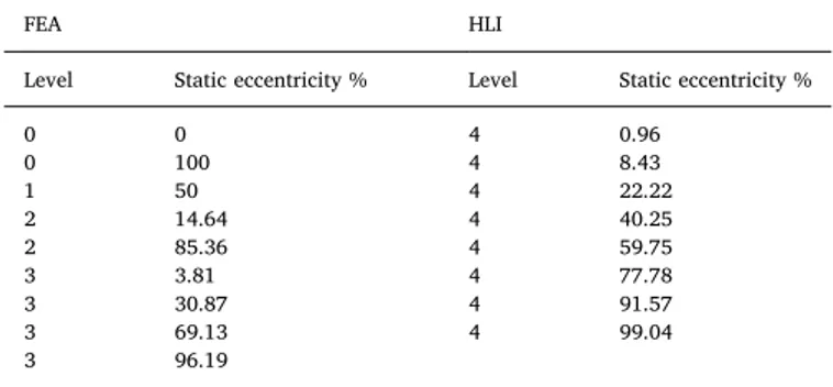
Table 2shows the GCL points for the first 5 hierarchical levels. For the levels 0–3 FEA software is used to compute the inductances matrix.
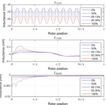
Fig. 6 shows some inductances computed for different degrees of a static eccentricity fault using the procedure show inFig. 4. Afterwards these results are used to create the HLI polynomial of(14)with which it is possible to compute the inductances matrix for the whole range of severity of the fault. Finally, the inductances matrix for the level 4 in
Table 2are computed using the proposed method (HLI) and compared with the results of FEA.
5.2. Results
With the HLI polynomial obtained using levels 0–3 ofTable 2the inductances matrix for level 4 are computed and compared with those obtained with FEA software, to check the validity of the method. The mutual inductances between stator phases 1 and 2, between stator phase 1 and rotor bar 1 and between rotor bars 1 and 2, depending on the rotor position have been computed for three levels of static
Table 2
Set of the GCL points of static eccentricity for performing the HLI.
FEA HLI
Level Static eccentricity % Level Static eccentricity %
0 0 4 0.96 0 100 4 8.43 1 50 4 22.22 2 14.64 4 40.25 2 85.36 4 59.75 3 3.81 4 77.78 3 30.87 4 91.57 3 69.13 4 99.04 3 96.19
eccentricity using the proposed method (HLI) and using FEA are shown inFigs. 7–9respectively.
As shown inFigs. 7–9, the proposed method obtains the same results as those obtained with FEA with a small error, but with much less computing power requirements. In fact, once the polynomial HLI are obtained, the computation of the inductances matrix for a new value of
eccentricity requires just30seconds and a disk space of 5 MB, versus the 10.2hours and 13.45 GB needed if FEA, using the procedure shown in
Fig. 4. That means boosting the simulation time in 99.92% and reducing 99.96%the amount of memory resources required.
Fig. 6. Mutual inductance between the stator phase 1 and the stator phase 2 (top), between stator phase 1 and rotor bar 1 (middle) and between rotor bar 1 and rotor bar 2 (bottom) for 5 different degrees of static eccentricity (inside the levels 0–3 obtained with the GCL set) depending on the rotor position using FEA.
Fig. 7. Mutual inductance between the stator phase 1 and the stator phase 2 for three different levels of static eccentricity depending on the rotor position using FEA software and the proposed method (HLI).
Fig. 8. Mutual inductance between the stator phase 1 and the rotor bar 2 for three different levels of static eccentricity depending on the rotor position using FEA software and the proposed method (HLI).
Fig. 9. Mutual inductance between the rotor bar 1 and the rotor bar 2 for three different levels of static eccentricity depending on the rotor position using FEA software and the proposed method (HLI).
5.3. Summary of the steps of the proposed method
The proposed method can be summarized in the following steps. These steps would be the same for other types of faults such as rotor asymmetries, inter-turn stator winding short-circuit, other types of ec-centricities (dynamic, mixed), etc.:
1. Select the type of fault to analyse.
2. Define the parametric space of the selected fault. 3. Create the set of GCL points using(13).
4. Compute the inductances matrix for the set of GCL points (step 3) using FEA software and the procedure shown inFig. 4.
5. Use the results of the FEA simulation (step 4) to create the HLI polynomial basis as in(14).
6. Compute the inductances matrix for the desired degree of severity of the fault using the HLI polynomial basis computed in the step 5.
6. Simulation implementation
To test the model and parameters computed in the previous sec-tions, the model has been implemented in the HIL model OP4500 from OPAL-RT shown inFig. 10and whose main characteristics are detailed in theAppendix A.
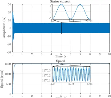
This model runs in real time, and the stator currents can be acquired through the analogue outputs of the HIL. Hence, these signals can be used to test fault diagnosis techniques implemented in embedded de-vices, to generate signals to develop and train expert fault diagnosis systems, to create data bases, to establish the thresholds for different types of faults, etc.Fig. 11shows the model running in real time in the OP4500 HIL, with the stator currents of the simulated model being acquired using a digital oscilloscope connected to the analogue outputs of the HIL. On the other hand,Fig. 12shows the stator current and the speed of the faulty IM during a simulation test.
6.1. Fault diagnosis using the proposed faulty IM model and the HIL model OP4500.
The use of the stator current has become a notable approach for con-dition monitoring of the IMs, not only due to its low requirements in hardware and software but also due to the great amount of information that contains about the state of the IM. In fact, each fault induces or amplifies frequency components in the stator current which can be related to both mechanical faults (rolling bearings, eccentricity) and magnetic and electric asymmetries (stator winding short-circuits, rotor broken bars)[10].
The presence of the principal slot harmonics (PSHs) due to rotor slot harmonics is used for the sensorless speed estimation of IMs of most drives and for the detection of eccentricity faults. The PSH and the static and dynamic eccentricity harmonics are given as[59]:
= ± ±
f kR n s p f [( )1 ]
h d 1 (15)
where k is any positive integer,Rare the number of rotor slots,ndis0
for static eccentricity or positive integer for dynamic eccentricity, s is the slip, p is the number of pole pairs, is the order of the stator time harmonics and f is the mains frequency. In this case and as can be seen in Table 1,R=28and =p 2. Moreover, as the static eccentricity re-lated harmonic components are being studiednd=0.
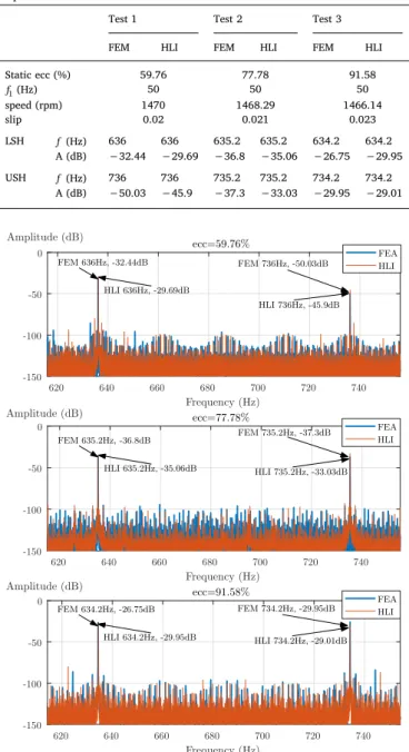
To check the validity of the inductances matrix obtained using the proposed method the three tests with different degree of static eccen-tricity shown inTable 3have been performed. These results are com-pared with those obtained with inductances matrix computed using FEA. This table also includes the frequencies (f) in Hz and amplitudes (A) in dB of the harmonic fault components more relevant for fault diagnosis which are the lower side harmonic (LSH) and the upper side harmonic (USH) corresponding to 1and+ 1of± in(15). The stator currents obtained in these tests have been sampled using a digital os-cilloscope during100seconds at a sampling frequency of10kHz.
Fig. 13shows the spectrum of the tests shown inTable 3. To better illustrate the results, the spectrum has been plotted only in the fre-quency range where the LSH and USH due to static eccentricity should appear. These results reinforces the use of the proposed method (HLI) to compute the inductance matrix of the faulty model for fault diagnosis purposes. The spectra obtained related to fault harmonic components are the same, with small errors, as if the matrix was fully computed with FEA.
Fig. 10. HIL hardware, model OP4500 from OPAL RT technologies, used to simulate the faulty induction motor model in real time.
Fig. 11. (Top) Faulty IM model developed in the previous sections running in real time in the OP4500 HIL while the stator currents are acquired using a digital oscilloscope connected to the analogue outputs of the HIL. (Bottom) Detail of the rear part of the HIL where the connections with the analogue outputs can be seen.
Fig. 12. Stator current (top) and speed (bottom) of the IM faulty model de-veloped with a static eccentricity of 59.76% during a simulation.
7. Conclusions
The parameter calculation of the equivalent circuit of the IM are computed by FEA is a promising technique to obtain accurate faulty IM models which can be run in real time. These models can be used in speeding up the development and test of new on-line condition mon-itoring techniques implemented in embedded devices. In this paper the SSL and the HLI are proposed to reduce the requirements needed to obtain accurate models of the faulty IM that cover the whole range of severity of a given fault. The method has been theoretically introduced and the results have been validated and compared with those obtained using FEA. In this paper, the method has been illustrated using the static eccentricity fault, but the same procedure can be used to obtain
the inductances matrix for other types of faults such as rotor asym-metry, inter-turn stator winding short-circuits, etc.
Using the proposed method (SSL and polynomial HLI) the para-meters of a model for the whole range of severity degrees of the IM fault are obtained with a similar accuracy than FEA, at a fraction of its computing cost. Indeed, as it has been demonstrated, the results ob-tained with the proposed method, regarding to fault diagnosis purposes, are precise and the same as the obtained using FEA but with a ex-tremely faster computation of the parameters of the equivalent circuit of the IM. It should be noted as a novelty, in addition to the benefits already mentioned, that in this paper, the SSL is used to obtain the parametric solutions, instead of the predictions to initialize the de-terministic model at a new sampling point, as in other works published in the technical literature. In this way the proposed method not only reduces the number of FEA simulations but also greatly reduces the computing resources required. In fact, the proposed method boosts 99.9% the simulation time and it reduces 99.9% the memory resources required to compute the inductance matrix for a new degree of a given fault.
Acknowledgements
This work was supported by the Spanish “Ministerio de Educación, cultura y Deporte” in the framework of the “Programa Estatal de Promoción del Talento y su Empleabilidad en I+D+i, Subprograma Estatal de Movilidad, del Plan Estatal de Investigación Científica y Técnica y de Innovación 2013–2016” in the subframework “Estancias de movilidad en el extranjero José Castillejo para jóvenes doctores”.
Appendix A. HIL OP4500 main features
Real-time target: 4 INTEL processor cores 3.3 GHz (only 1 core ac-tivated).
Solid state disk: 125 Gb. Memory RAM: 4 Gb.
Real-time operating system: Linux RedHat.
Xilinx Kintex 7 FPGA (326.000 Logic cells and 840 DSP slice). Sampling Rate: 200 MHz.
96 User Inputs/Outputs (I/O): 16 analog inputs and 16 analog outputs, 24 digital inputs and 24 digital outputs, 8 RS422 digital inputs and 8 RS422 digital outputs.
References
[1] Saidur R. A review on electrical motors energy use and energy savings. Renew Sustain Energy Rev 2010;14(3):877–98.
[2] Karmakar S, Chattopadhyay S, Mitra M, Sengupta S. Induction motor fault diag-nosis: general discussion and research scope. Induction motor fault diagnosis. Springer; 2016. p. 153–8.
[3] Culbert I, Letal J. Signature analysis for online motor diagnostics: early detection of rotating machine problems prior to failure. IEEE Ind Appl Mag 2017;23(4):76–81. [4] Glowacz A, Glowacz Z. Diagnostics of stator faults of the single-phase induction
motor using thermal images, moasos and selected classifiers. Measurement 2016;93:86–93.
[5] Frosini L, Harlisca C, Szab L. Induction machine bearing fault detection by means of statistical processing of the stray flux measurement. IEEE Trans Ind Electron 2015;62(3):1846–54.
[6] Seshadrinath J, Singh B, Panigrahi BK. Vibration analysis based interturn fault di-agnosis in induction machines. IEEE Trans Ind Inf 2014;10(1):340–50. [7] Delgado-Arredondo PA, Morinigo-Sotelo D, Osornio-Rios RA, Avina-Cervantes JG,
Rostro-Gonzalez H, de Jesus Romero-Troncoso R. Methodology for fault detection in induction motors via sound and vibration signals. Mech Syst Sig Process 2017;83:568–89.
[8] Stone GC, Sedding HG, Chan C. Experience with online partial-discharge mea-surement in high-voltage inverter-fed motors. IEEE Trans Ind Appl 2018;54(1):866–72.
[9] Mirzaeva G, Saad KI, Jahromi MG. Comprehensive diagnostics of induction motor faults based on measurement of space and time dependencies of air gap flux. IEEE Trans Ind Appl 2017;53(3):2657–66.
[10] Siddiqui KM, Sahay K, Giri V. Health monitoring and fault diagnosis in induction motor-a review. Int J Adv Res Electr Electron Instrument Eng 2014;3(1):6549–65. [11] Sahraoui M, Cardoso AJM, Ghoggal A. The use of a modified Prony method to track
Table 3
Test performed with the HIL using the inductances matrix computed with the proposed method HLI and with FEA.
Test 1 Test 2 Test 3 FEM HLI FEM HLI FEM HLI Static ecc (%) 59.76 77.78 91.58 f1(Hz) 50 50 50 speed (rpm) 1470 1468.29 1466.14 slip 0.02 0.021 0.023 LSH f(Hz) 636 636 635.2 635.2 634.2 634.2 A (dB) −32.44 −29.69 −36.8 −35.06 −26.75 −29.95 USH f(Hz) 736 736 735.2 735.2 734.2 734.2 A (dB) −50.03 −45.9 −37.3 −33.03 −29.95 −29.01
Fig. 13. Stator current spectrum obtained for three different levels of static eccentricity using FEA software and the proposed method (HLI) to compute the inductance matrix of the model. Besides, the frequency of the fault harmonic related components due to static eccentricity are highlighted for both the in-ductance matrix computed using FEA software and the proposed method (HLI).
the broken rotor bar characteristic frequencies and amplitudes in three-phase in-duction motors. IEEE Trans Ind Appl 2015;51(3):2136–47.
[12] Naha A, Samanta AK, Routray A, Deb AK. Low complexity motor current signature analysis using sub-Nyquist strategy with reduced data length. IEEE Trans Instrument Meas PP 2017;99:1–11.
[13] Bravo-Imaz I, Ardakani HD, Liu Z, Garca-Arribas A, Arnaiz A, Lee J. Motor current signature analysis for gearbox condition monitoring under transient speeds using wavelet analysis and dual-level time synchronous averaging. Mech Syst Sig Process 2017;94:73–84.
[14] Kim J, Shin S, Lee SB, Gyftakis KN, Drif M, Cardoso AJM. Power spectrum-based detection of induction motor rotor faults for immunity to false alarms. IEEE Trans Energy Convers 2015;30(3):1123–32.
[15] Yang C, Kang TJ, Lee SB, Yoo JY, Bellini A, Zarri L, et al. Screening of false in-duction motor fault alarms produced by axial air ducts based on the space-har-monic-induced current components. IEEE Trans Ind Electron 2015;62(3):1803–13. [16] Gritli Y, Rossi C, Casadei D, Filippetti F, Capolino GA. A diagnostic space
vector-based index for rotor electrical fault detection in wound-rotor induction machines under speed transient. IEEE Trans Ind Electron 2017;64(5):3892–902.
[17] Burriel-Valencia J, Puche-Panadero R, Martinez-Roman J, Sapena-Bano A, Pineda-Sanchez M. Short-frequency fourier transform for fault diagnosis of induction ma-chines working in transient regime. IEEE Trans Instrum Meas 2017;66(3):432–40. [18] Sapena-Bano A, Pineda-Sanchez M, Puche-Panadero R, Martinez-Roman J, Mati D. Fault diagnosis of rotating electrical machines in transient regime using a single stator current's FFT. IEEE Trans Instrum Meas 2015;64(11):3137–46.
[19] Duque-Perez O, Garcia-Escudero L-A, Morinigo-Sotelo D, Gardel P-E, Perez-Alonso M. Analysis of fault signatures for the diagnosis of induction motors fed by voltage source inverters using anova and additive models. Electr Power Syst Res 2015;121:1–13.
[20] Yin Z, Hou J. Recent advances on svm based fault diagnosis and process monitoring in complicated industrial processes. Neurocomputing 2016;174:643–50. [21] Ali JB, Fnaiech N, Saidi L, Chebel-Morello B, Fnaiech F. Application of empirical
mode decomposition and artificial neural network for automatic bearing fault di-agnosis based on vibration signals. Appl Acoust 2015;89:16–27.
[22] Samanta AK, Naha A, Basu D, Routray A, Deb AK. Online condition monitoring of traction motor. Handbook of research on emerging innovations in rail transporta-tion engineering. IGI Global; 2016. p. 489–523.
[23] Raksa M, Likitjarernkul T, Sengchuai K, Jindapetch N, Thongnoo K. An fft com-putation minimisation for an fpga-based mcsa while preserving frequency resolu-tion. Pertanika J Sci Technol 2017;25:105–12.
[24] Capolino G-A, Antonino-Daviu JA, Riera-Guasp M. Modern diagnostics techniques for electrical machines, power electronics, and drives. IEEE Trans Ind Electron 2015;62(3):1738–45.
[25] Sapena-Bano A, Burriel-Valencia J, Pineda-Sanchez M, Puche-Panadero R, Riera-Guasp M. The harmonic order tracking analysis method for the fault diagnosis in induction motors under time-varying conditions. IEEE Trans Energy Convers 2017;32(1):244–56.
[26] Palácios RHC, da Silva IN, Goedtel A, Godoy WF. A novel multi-agent approach to identify faults in line connected three-phase induction motors. Appl Soft Comput 2016;45:1–10.
[27] Mustafa MO, Varagnolo D, Nikolakopoulos G, Gustafsson T. Detecting broken rotor bars in induction motors with model-based support vector classifiers. Control Eng Pract 2016;52:15–23.
[28] Kia SH, Henao H, Capolino G-A. Trends in gear fault detection using electrical signature analysis in induction machine-based systems. Electrical machines design, control and diagnosis (WEMDCD), 2015 IEEE workshop on. IEEE; 2015. p. 297–303.
[29] Ghorbanian V, Faiz J. A survey on time and frequency characteristics of induction motors with broken rotor bars in line-start and inverter-fed modes. Mech Syst Sig Process 2015;54:427–56.
[30] Liang J, Qiu Y, Zhao M, Kang S, Lu H. The modeling and numerical simulations of wind turbine generation system with free vortex method and simulink. Energy Convers Manage 2015;103:762–77.
[31] Shukla RD, Tripathi RK. Isolated wind power supply system using double-fed in-duction generator for remote areas. Energy Convers Manage 2015;96:473–89. [32] Tavana NR, Dinavahi V. Real-time nonlinear magnetic equivalent circuit model of
induction machine on FPGA for hardware-in-the-loop simulation. IEEE Trans Energy Convers 2016;31(2):520–30.
[33] Chen X, Hu J, Chen K, Peng Z. Modeling of electromagnetic torque considering saturation and magnetic field harmonics in permanent magnet synchronous motor for hev. Simul Model Pract Theory 2016;66:212–25.
[34] Zhou Y, Bao X, Di C, Wang L. Analysis of dynamic unbalanced magnetic pull in induction motor with dynamic eccentricity during starting period. IEEE Trans Magn 2016;52(7):1–4.
[35] Taegen F, Hommes E. General system of equations of squirrel-cage motor taking into account space harmonic fields. 1. General theory. Archiv Fur Elektrotechnik 1972;55(1):21.
[36] Pantea A, Yazidi A, Betin F, Taherzadeh M, Carrière S, Henao H, et al. Six-phase induction machine model for electrical fault simulation using the circuit-oriented method. IEEE Trans Ind Electron 2016;63(1):494–503.
[37] Naderi P, Taheri A. Slot numbering and distributed winding effects analysis on the torque/current spectrum of three-phase wound-rotor induction machine using discrete modeling method. Electr Power Compon Syst 2015;43(15):1717–26. [38] Chang H-C, Lin S-C, Kuo C-C, Hsieh C-F. Induction motor diagnostic system based
on electrical detection method and fuzzy algorithm. Int J Fuzzy Syst 2016;18(5):732–40.
[39] Dong G, Ojo O. Efficiency optimizing control of induction motor using natural variables. IEEE Trans Ind Electron 2006;53(6):1791–8.
[40] Amiri N, Ebrahimi S, Chapariha M, Jatskevich J, Dommel HW. Voltage-behind-reactance model of six-phase synchronous machines considering stator mutual leakage inductance and main flux saturation. Electr Power Syst Res 2016;138:155–64.
[41] Gradev S, Reuss J, Herzog H-G. A general voltage-behind-reactance formulation of a multivoltage n 3-phase hybrid-excited synchronous machine. IEEE Trans Energy Convers 2016;31(4):1452–61.
[42] Faiz J, Moosavi SM, Abadi MB, Cruz SM. Magnetic equivalent circuit modelling of doubly-fed induction generator with assessment of rotor inter-turn short-circuit fault indices. IET Renew Power Gener 2016;10(9):1431–40.
[43] Martinez J, Belahcen A, Detoni J. A 2D magnetic and 3D mechanical coupled finite element model for the study of the dynamic vibrations in the stator of induction motors. Mech Syst Sig Process 2016;66:640–56.
[44] Gu B-G. Offline interturn fault diagnosis method for induction motors by impedance analysis. IEEE Trans Ind Electron 2018;65(7):5913–20.
[45] Jerkan D, Marčetić D. Advanced model of IM including rotor slot harmonics. COMPEL: Int J Comput Math Electr Electron Eng 2015;34(1):261–78.
[46] Ojaghi M, Sabouri M, Faiz J. Analytic model for induction motors under localized bearing faults. IEEE Trans Energy Convers 2018;33(2):617–26.
[47] Aguiar VP, Pontes RS, Neto TRF, Souza KN. Comparison of fea field models com-bined with analytical method to determine the performance characteristics of high efficiency induction motors. Power electronics conference and 1st southern power electronics conference (COBEP/SPEC), 2015 IEEE 13th Brazilian. IEEE; 2015. p. 1–6.
[48] Ling Z, Zhou L, Guo S, Zhang Y. Equivalent circuit parameters calculation of in-duction motor by finite element analysis. IEEE Trans Magn 2014;50(2):833–6. [49] Poveda-Lerma A, Sapena-Bano A, García-Lameiras A, Riera-Guasp M,
Martinez-Roman J. Induction machine model for fault diagnosis using hardware in the loop and finite element analysis. Congress on numerical methods in engineering CMN2017, vol. 3. 2017. p. 5.
[50] Saleem A, Issa R, Tutunji T. Hardware-in-the-loop for on-line identification and control of three-phase squirrel cage induction motors. Simul Model Pract Theory 2010;18(3):277–90.
[51] Montgomery DC. Design and analysis of experiments. John Wiley & Sons; 2017. [52] Quarteroni A, Manzoni A, Negri F. Reduced basis methods for partial differential
equations: an introduction vol. 92. Springer; 2015.
[53] Benner P, Gugercin S, Willcox K. A survey of projection-based model reduction methods for parametric dynamical systems. SIAM Rev 2015;57(4):483–531. [54] Chung E, Efendiev Y, Hou TY. Adaptive multiscale model reduction with
general-ized multiscale finite element methods. J Comput Phys 2016;320:69–95. [55] Borzacchiello D, Aguado JV, Chinesta F. Non-intrusive sparse subspace learning for
parametrized problems. Arch Comput Methods Eng 2017:1–24.
[56] Horen Y, Strajnikov P, Kuperman A. Simple mechanical parameters identification of induction machine using voltage sensor only. Energy Convers Manage
2015;92:60–6.
[57] Chatterjee A, Chatterjee D. An improved excitation control technique of three-phase induction machine operating as dual winding generator for micro-wind domestic application. Energy Convers Manage 2015;98:98–106.
[58] Peherstorfer B, Zimmer S, Bungartz H-J. Model reduction with the reduced basis method and sparse grids. Sparse grids and applications. Springer; 2012. p. 223–42. [59] Oumaamar MEK, Maouche Y, Boucherma M, Khezzar A. Static air-gap eccentricity fault diagnosis using rotor slot harmonics in line neutral voltage of three-phase squirrel cage induction motor. Mech Syst Sig Process 2017;84:584–97.