Science Arts & Métiers (SAM)
is an open access repository that collects the work of Arts et Métiers Institute of
Technology researchers and makes it freely available over the web where possible.
This is an author-deposited version published in: https://sam.ensam.eu Handle ID: .http://hdl.handle.net/10985/11336
To cite this version :
Ousmane FALL, JeanFrederic CHARPENTIER, Ngac Ky NGUYEN, Paul LETELLIER
-Performances comparison of different concentrated-winding configurations for 5-phase PMSG in normal and faulty modes in flux weakening operation for fixed pitch tidal turbines - In: 2016 XXII International Conference on Electrical Machines (ICEM), Suisse, 2016-09 - International Conference on Electrical Machines (ICEM; 2016;22) - 2016
Any correspondence concerning this service should be sent to the repository Administrator : archiveouverte@ensam.eu
ΦAbstract -- This paper aims to evaluate some configurations
of windings for low speed high power 5-phase permanent magnet synchronous generators (PMSG) associated to fixed pitch tidal turbines. Several Fractional-Slot Concentrated-Windings has been considered and compared for these specifications. The proposed structures are compared in terms of torque VS speed characteristics, including flux weakening operation, in healthy and faulty modes. In fault mode, the failure of one and two phases is considered. The results show that concentrated windings can be particularly useful for these particular specifications.
Index Terms--Synchronous generator, permanent magnet,
fault tolerance, open-circuit fault, tooth concentrated winding configuration, flux weakening, multiphase machines.
I. INTRODUCTION
NCREASING robustness and minimizing maintenance operations is a feature key for some specific applications based on electrical drives. Using multiphase drives instead of 3-phase ones is interesting for high reliability and high power applications because of their fault tolerance capability, their low torque pulsations at low frequencies and their ability to reduce the electrical ratings of the electronic components by power splitting[1, 2] These characteristics are particularly relevant in the high power tidal stream turbine context where it is desirable to produce electricity even if a fault occurs until a repair can be made. For off-shore tidal current application, a fault tolerant system is necessary because technical repairs and maintenance operations are limited by the high difficulties to access to the systems. This is why the ability of the system to harness energy during a long time even if a fault occurs is a key feature. For renewable energy systems, the more encountered faults on the electrical chain are due to the converter and leads after detection to open-phase configuration [3]. That is why, open circuited phase faults
O. Fall is with Research Institute of French Naval Academy, BCRM Brest, 29240 Brest, France (e-mail: ousmane.fall@ecole-navale.fr).
J.F. Charpentier is with Research Institute of French Naval Academy, BCRM Brest, 29240 Brest, France(e-mail: jean-frederic.charpentier@ecole-navale.fr).
N.K. Nguyen is with the Laboratory of Electrical Engineering and Power Electronics of Lille (L2EP), Arts et Métiers ParisTech, 8 bd Louis XIV 59046 Lille, France (e-mail: ngacky.nguyen@ensam.eu)
P. Letellier is with Jeumont-electric, 367 Rue de l’industrie, 59460 Jeumont, France (e-mail: paul.letellier@jeumontelectric.com)
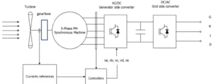
gearbox
Fig. 1. General scheme of the turbine/generator and drive association.
are considered in this paper.
If a PM generator is associated with a fixed pitch turbine, power limitation operation at high values of the tidal stream can be done based on flux weakening operation of the PMSG as demonstrated in [4, 5]. This strategy implies to operate the generator in a wide range of speed at a constant power under either healthy mode or faulty mode (in fault mode, the generator will be, of course, operated with a reduced power and reduced range of speed).
In this work, a 5-phase PM generator which is associated to a 1-stage gearbox (gearbox ratio around 5) and a fixed pitch tidal stream tidal turbine is considered. The general scheme of the turbine/generator and drive association is shown in Fig. 1.
Reference [6] originally proposes a control strategy being able to operate a 5-phase induction machine in healthy and also in faulty mode (open phase mode). This strategy has been adapted by the authors in [7] to flux weakening operations of 5-phase PM synchronous machines by taking into account the voltage and current limit related to machine and drive association. The method proposed in [7] is based on Maximum Torque Per Ampere control strategy (MTPA) under the base speed and flux weakening operation over the base speed with objective to maximize the available torque (and harnessed power) in a wider range of speed as much as possible in healthy and fault cases.
However, the value of the base speed, the corresponding base torque/power and the flux weakening range of speed depend not only on the control algorithms but also significantly on the electrical parameters of the machine and drive (these parameters are the waveform of the back-EMF, the self and mutual inductance values of the generator and the maximum voltage and current of the machine and the drive). Parameters related to the machine (back-EMF and
Performances comparison of different
concentrated-winding configurations for 5-phase
PMSG in normal and faulty modes in flux
weakening operation for fixed pitch tidal turbines
Ousmane Fall, Jean-Frédéric Charpentier, Ngac-Ky Nguyen, Paul Letellier
inductances) are strongly linked to the design options and particularly to the winding topology. Fractional-Slot Concentrated-Windings (FSCW) has been the subject of several studies in the last few years [8-10]. Indeed FSCW can be advantageous compared to classical distributed-windings in terms of fault tolerance, high density related to short end windings and low cogging torque. The present paper studies the possibility to use FSCW to obtain a performance as good as possible for the considered application. Several configurations of FSCW for 5-phase electrical generators will be investigated to evaluate the torque-speed characteristic in healthy and faulty modes taking into account the electrical limits of the drive (maximal voltage and current).
The paper is organized as follows, section II is dedicated to the modelling of 5-phase PM machines. The choice of slot/pole combination, the design methodology and the analytical calculation of inductances and back-EMF of the fault-tolerant PMSG with FSCW is presented in section III. Some results are presented in section IV in order to highlight the comparison between different configurations of 5-phases generators. Conclusions are given in section V.
II. 5-PHASE
PMSG– MODELLING ANDCONTROLTo establish an electrical model of a 5-phase PM machine, the following assumptions are considered:
• The considered machine is wye connected and a 5-leg PWM IGBT converter (PWM rectifier) is used in the machine side as shown in Fig. 2.
• The saturation of the machine iron is not taken into account in the calculation of the back-EMF and the fluxes
• Saliency is neglected
• The phases are regularly switched.
Fig. 2. Generator/converter association.
With these assumptions, the voltage vector can be written as:
[ ]
s[ ] [ ] [ ]
d v R i e dt φ = + + (1) where: •[ ] [
v = va vb vc vd ve]
• the flux vector
[ ] [
φ = φ φ φ φ φa b c d e]
• the current vector is
[ ] [
i = ia ib ic id ie]
• the back-EMF vector is[ ] [
e = ea eb ec ed ee]
In order to have an easier control, the model is done in the 2 rotor frames obtained by applying generalized Concordia and Park transformations, as explained in [11, 12]. This modelling allows splitting the phase 5-dimensional electrical variables into 2 d-q rotating frames (d1q1 and d3q3) and a
zero-sequence component. With a wye connection the zero sequence current is nullified. Then electromagnetic torque can be expressed as:
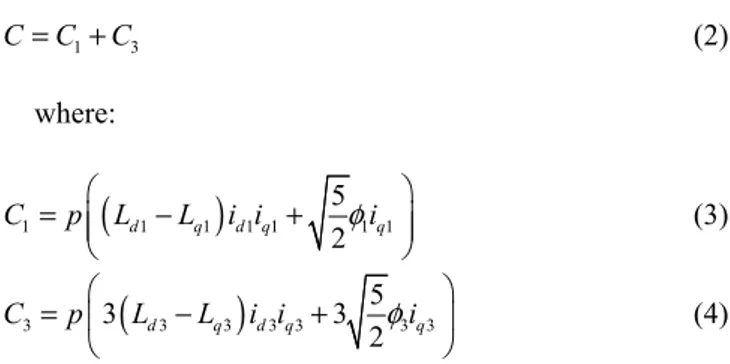
1 3 C C= +C (2) where:
(
)
1 1 1 1 1 1 1 5 2 d q d q q C = p L −L i i + φi (3)(
)
3 3 3 3 3 3 3 5 3 3 2 d q d q q C = p L −L i i + φi (4)C1 and C3 are the torques related to the main d-q frame
(d1q1, linked to the fundamental harmonics) and the second
d-q frame (d3q3, related to the 3rd harmonics) respectively.
Maximum Torque Per Ampere (MTPA) control strategy can be applied even with open-circuit fault [13, 14]. However, these approaches have been proposed without any constraint on voltage and current related to the rated values of the drive. At high speed operation, a flux weakening operation is sometimes used and all analytical formulations given by MTPA strategy are no more available. In [15] a flux weakening strategy for a 5-phase PM synchronous machine has been presented for healthy mode. In [7] a control strategy which allows flux weakening operation both in healthy and fault modes has been presented. With this strategy, it should be noticed that if the back-EMF has a negligible third harmonic, iq1 and id1 can be controlled to be
constant in steady state (id1 is controlled to be non-null in
flux weakening operations) as presented in [7] in healthy mode and fault mode. The experimental results of this control strategy has been given in [16]. Nevertheless, if the back-EMF has a significant part of the third harmonic, a pulsating torque is introduced by the control method proposed in [7] in fault mode, because iq3 cannot be
maintained as constant if both id1 and iq1 are controlled as
constant. To solve this problem, a 5-H-bridge converter instead of a 5-leg inverter can be used to add one supplementary degree of freedom (zero sequence current is non null). Then, new references of current can be determined.
However, another solution is to minimize the third harmonics of the EMF acting on the machine design. This is why in the studied cases the magnet arc to pole ratio is fixed to 2/3. This design option allows to minimize the third harmonics of the back-EMF for all the considered structures.
After knowing the analytical expressions of phases’
currents which are able to keep a constant electromagnetic torque, a numerical optimization is done in order to find the values of (id1,iq1) which maximize the torque value while
satisfying voltage and current drive constraints (i.e. |ia,b,c,d;e|<Imax and |va,b,c,d;e|<Vmax). As described in [7] this
optimization is carried out by using fmincon function, from Matlab.
III. 5-PHASEGENERATORSBACK-EMFAND INDUCTANCECALCULATIONWITHFSCW
TOPOLOGY
To choose FSCW topology several constraints must be considered:
• symmetry conditions must be satisfied : the number of slots Qs per phase (m is the number of phases) must be an integer value, such as:
•the value
2
s
Q
m must be an integer for single
layer winding • the value Qs
m must be an integer for double
layer winding
• Winding coefficient for the first harmonics must be
higher than 0.95 to improve the torque to mass ratio of the generator.
• The greatest common divisor of Q and p (p is the s
number of pole pairs), gcd(Q , p), must be s
relatively high to have a good repartition of radial forces in the machine.
• The lowest common multiple of Q and 2p , s
lcm(Q ,2p), must be high to minimize cogging s
torque
• The influence of magneto motive force spectrum in
the magnet losses must be carefully checked. After choosing the slot/pole combination, the winding distribution is determined in a similar way as the one described in [17] applied for 3-phase machines. This method is extended for multiphase machines. In order to be able to calculate the torque-speed characteristics of the proposed configurations in healthy and fault mode, the back-EMF waveforms and the mutual and self-inductance values have to be calculated. To be able to explore very quickly a lot of configurations, these calculations are done by analytical method and have been validated by 2-D finite element (FE) method. These validation shows that the differences between FE and analytical calculations are lower than 10%.
The winding coefficients are calculated by using the EMF phasors method, described in [17] and [18]. The back-EMF waveform is determined from the calculation of the radial component of the flux density in the airgap. The expression of this component (eq. (5)) is calculated by solving Maxwell’s equations separating radial and tangential variables, using the method described in[19].
( )
( )
(
)
(
)
(
)
( )(
)
( 1) 0 2 1,3,5... 2 1 1 2 2 2 2 2 2 1 1 2 , 1 1 2 1 1 1 cos np n r m n r np np np np m r m r np np np np np r r s r m s r m r r np np np s M np B r R np np R R R np R R R R R R R r R r np μ θ μ μ μ μ μ θ ∞ − − = + − − + − = − − + − + + − − − − +
(5) 0 sin 2 2 2 m n n B M n πβ β πβ μ = (6)p : number of pole pairs
s
R : inner stator radius
m
R : outer magnet radius
r
R : outer rotor radius
r
μ : relative permeability of magnet 0
μ
: vacuum permeabilitym
B
: remanenceβ
: magnet pole-arc to pole pitch ratioSlotting effect is taken into account using a permeance function as presented in [20].
( )
( ) ( )
_ , , ,
r real r
B rθ =λ θ r B rθ (7)
where
λ
is the relative airgap permeance.The back-EMF waveform can then be determined by: ( ) d t e dt φ = − (8)
Where
φ
( )
t
is the magnetic flux in one phase obtainedby integration of the radial component of flux density in the air-gap.
In PM machines, slot/pole combinations have a strong impact on the torque-speed characteristic because the back-electromotive force (back-EMF) harmonics and inductances are depending on these combinations [21]. So, knowing the inductances values is necessary to make comparison between several structures of FSCW. The knowledge of the inductance values allows also to evaluate the electrical time constant of the d1q1 and d3q3 systems. These time constants
have to be compatible with the converter frequency to be able to control the current in the two subsystems.
Analytical calculation of inductances is done as follow:
p m s ew tt
L
=
L
+
L
δ+ +
L
L
+
L
(9)where: p
L
: one phase self-inductance mL
: magnetizing inductances
L
: slot leakage inductance ewL
: end-winding leakage inductancett
L
: tooth-tip leakage inductanceThe leakages inductances are calculated by the method presented in [22]:
( )
2 0 1 s u m a m rR L
L
F
d
h
e
μ
θ θ
μ
=
+
(10)( )
( )
(
2 2)
0 1 s u a a m rR L
L
F
F
d
h
e
δμ
θ
θ θ
μ
=
−
+
(11) 2 0 s slot u q u L =N μL Z λ (12) 2 0 tt slot u q tt L =N μ L Z λ (13)μo is the vacuum permeability,
F
ais the winding functionof the phase “a” and Fa1 is the 1st harmonic of Fa. Nslotis the
number of slots per phase,
Z
qis the number of conductorper slot per phase, and L is the active length of the machine. u e is the mechanical airgap value,h is the magnet m
thickness and
δ
= +
e h
m. uλ
is the slot leakage factor andλ
ttis the tooth-tipleakage factor. They can be calculated as follow. -For double layer winding
3 4 1 2 4 1 2 3 4 1 4 1 1 4 ' ln ' 3 4 u h h h h h b h k k b b b b b b b λ = − + + + + − (14)
'
h
is the gap value between the two layers in the sameslot.
-For single layer winding:
3 4 1 2 4 3 4 1 4 1 1 ln 3 u h h h h b b b b b b b λ = + + + − (15) and 2 1 2 2 1 1 1 ln 4 arctan 2 4 2 tt b k b δ λ δ π δ = + + (16) h1, h4, b1, b4 are the geometrical parameters of the slot
presented in Fig. 3 and 2h =h3=b2=b3 0= . k1 and k2 are
given by 1 5 3 8 g k = + 2 1 2 g k = + Where g is calculated as in [22, 23] :
( )
1 1 cos slot N n n slot g N = γ =
(17) nγ
is the electrical angle between the current in the phase ‘a’ and the current of the other phase located in the same slot.Fig. 3. Slots scheme from [22].
It can be noticed that the expression of Lδ shows that PMSG with FSCW are characterized by a high value of self- inductance because of the high harmonics content of their winding function.
The mutual inductance between two different phases of PMSG is calculated as Mab=Mabm+Ms with:
( ) ( )
0 s u abm a b m r R L M F F d h e μ θ θ θ μ = +
(18) and 2 0 s slot u q Ms M = −N μL Z λ (19) Whereλ
Msis the permeance factor, calculated from [24] and adapted for 5-phase machines with FSCW. Fa, Fb arethe winding function of the phase “a” and the phase “b” respectively.
The term Mabm represents the mutual inductance term between the phase “a” and the phase “b” related to the coupling of the two phases corresponding to air gap fluxes. The term M represents the mutual inductance term related s to the coupling between phases located in the same slot and corresponds to fluxes located in the slot. This is why this term is only used for double layer winding [24].
Calculations of self and mutual inductances allow obtaining the cyclic inductances values in d-q frames using
generalized Park and Concordia transformations
[ ]
Lodq =[ ][ ][ ]
T5 L T5 t:[ ]
0 1 1 3 3 0 0 0 0 0 0 0 0 0 0 0 0 0 0 0 0 0 0 0 0 d q odq d q L L L L L L = (20) with: [ ]5 1 1 1 1 1 2 2 2 2 2 2 4 6 81 cos cos cos cos
5 5 5 5
2 4 6 8
2 0 sin sin sin sin
5 5 5 5
5
4 8 2 6
1 cos cos cos cos
5 5 5 5
4 8 2
0 sin sin sin s
5 5 5 T π π π π π π π π π π π π π π π = 6 in 5 π 2794
The use of the presented analytical models (for EMF and inductances) makes possible quick comparisons of torque-speed characteristics for several 5-phase FSCW structures.
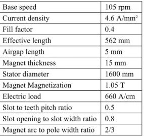
IV. TORQUE-SPEEDPERFORMANCECOMPARISON The studied generators are designed for a common data set corresponding to a realistic tidal stream generator with a number of poles around 60 (rated power about 1.05 MW at 105 rpm). These data corresponds to a reference 5-phase diametral windings machine. Common parameters of the generators are summarised in TAB. I.
TABLEI.COMMONPARAMETERSFORTHESTUDIEDPMSG
Base speed 105 rpm Current density 4.6 A/mm² Fill factor 0.4 Effective length 562 mm Airgap length 5 mm Magnet thickness 15 mm Stator diameter 1600 mm Magnet Magnetization 1.05 T Electric load 660 A/cm Slot to teeth pitch ratio 0.5 Slot opening to slot width ratio 0.8 Magnet arc to pole width ratio 2/3
For this common specifications set, a comparison between several structures of 5-phase FSCW is made. For all structures inductances and back-EMF are calculated. This calculation allows evaluating their torque VS speed characteristics in healthy and fault modes (one and two adjacent phases opened mode).
Several 5-phase PMSG structures are considered:
• S1: 60 slots and 58 poles structure with double layer FSCW (structure 1, noted S1)
• S2: 60 slots and 54 poles structure with single layer FSCW (structure 2 noted S2)
• S3: 60 slots and 54 poles structure with double layer FSCW (structure 3 notes S3)
• S4: 60 slots and 56 poles structure with double layer FSCW (structure 4 noted S4)
• S5: 45 slots and 54 poles structure with double layer FSCW (structure 5 noted S5)
The behaviours of these 5 structures are compared with the behaviour of the reference diametral winding machine (i.e. 300 slots, 60 poles, 1 layer (structure 0 noted S0)). For each structure the number of conductors per slot is calculated in order to reach the rated voltage value given in TAB. I at the base speed in healthy mode with rated sinusoidal current density and rated electric load value. For this base speed operating point, a MTPA control strategy is considered (1st
harmonics of EMF, [e] and current [i] are in phase).
For each structure, a torque-speed characteristic and a power/speed characteristic can be calculated for each mode
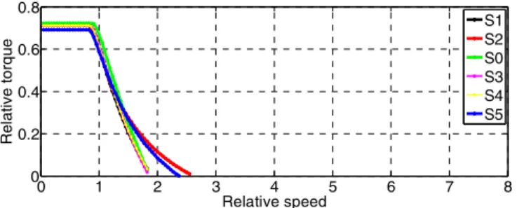
(healthy mode and fault modes). These characteristics are given in figures 5 to 10. The value of the power, torque and speed are given in per unit (p.u.). These p.u. values are obtained by normalizing to the rated values reached at the base speed of the reference machine (S0 structure) in healthy mode. 0 1 2 3 4 5 6 7 8 0 0.2 0.4 0.6 0.8 1 Relative speed Rel a ti ve t o rq u e S1 S2 S0 S3 S4 S5
Figure 5: Torque/speed characteristic in healthy mode
0 1 2 3 4 5 6 7 8 0 0.5 1 1.5 Relative speed Relat ive pow e r S1 S2 S0 S3 S4 S5
Figure 6: power/speed characteristic in healthy mode
In order to make comparison between the structures, several criteria are taken into account both in normal mode and in fault modes:
• The value of maximal electromagnetic torque (in p.u) in healthy mode and fault modes (this value is noted MT in table II)
• The range of operating speed, noted MS in table II (i.e the maximal speed where the energy can be harnessed)
• The power factor at rated point (base speed) given in table III
The results in healthy and fault mode for the maximal torque value (MT) shows that at low speed, the difference between the torques values is mainly due to the fundamental winding coefficient. Considering this fact structure S5 leads to a smaller value of maximal torque than the 4 other structures. The flux-weakening region is characterised by the relative inductances values. For example structures S2 and S5 have more flux-weakening capability in healthy and fault mode than the other structures, because of their high inductance value. They are able to operate in a wide range of speed even in fault mode. So they seem particularly suitable to be associated with a fixed pitch tidal turbine.
However, in the other hand these structures will have a lower power factor at base speed which leads to an oversizing of the machine side converter. This fact is particularly significant for structure S2 which is characterized by a power factor lower than 0.7 at base speed. Structures S1 and S4 have also more flux weakening capabilities than S0 (but significantly less than S2 and S5)
and have a higher power factor (0.852 and 0.864 respectively).
Considering the specific requirements of fixed pitch tidal turbine structures S2 and S5 seem attractive. S2 is characterized by a high level of base torque and large flux weakening capabilities which allow extracting energy efficiently in over speed operations even in fault modes, but have a relatively low power factor (0.66) at base speed. It leads to an oversizing and a overcost of the converter associated to the generator. S1, S3 and S4 has more limited over speed capabilities but are characterized by higher power factors. It can be noticed that FSCW structures are often associated with high contents of magneto motive forces (MMF) harmonics. This high content of MMF harmonics will be related to supplementary losses in the magnets which have to be considered carefully in the machine design process. 0 1 2 3 4 5 6 7 8 0 0.2 0.4 0.6 0.8 Relative speed Rel a ti ve t o rq ue S1 S2 S0 S3 S4 S5
Figure 7: Torque/speed characteristic in fault mode (1 phase opened)
0 1 2 3 4 5 6 7 8 0 0.2 0.4 0.6 0.8 Relative speed Re lat iv e p o w e r S1 S2 S0 S3 S4 S5
Figure 8: Power/speed characteristic in fault mode (1 phase opened)
0 1 2 3 4 5 6 7 8 -0.1 0 0.1 0.2 0.3 Relative speed Re la ti v e t o rq u e S1 S2 S0 S3 S4 S5
Figure 9: torque/speed characteristic in fault mode (2 adjacent phases opened) 0 1 2 3 4 5 6 7 8 -0.1 0 0.1 0.2 0.3 Relative speed Re la ti v e pow e r S1 S2 S0 S3 S4 S5
Figure 10: torque/speed characteristic in fault mode (2 adjacent phases opened)
TABLEII. TORQUE AND SPEED RANGE CHARACTERISTICS VALUES
Healthy mode 1 phase opened 2 phases opened
MT1 MS2 MT1 MS2 MT1 MS2 S0 1 2.54 0.72 1.83 0.276 1.27 S1 0.982 2.9 0.71 1.85 0.272 1.27 S2 0.987 >7 0.72 2.57 0.274 1.63 S3 0.975 2.65 0.71 1.86 0.271 1.27 S4 0.98 2.81 0.71 1.88 0.272 1.27 S5 0.951 >7 0.69 2.37 0.264 1.41
1 MTis the maximal torque valueat low speed, 2 MS : maximal relative speed
where the energy can be harnessed
TABLE III. Power factor values at base speed in healthy mode
S0 S1 S2 S3 S4 S5 PF 0.88 0.857 0.66 0.874 0.864 0.758
V. CONCLUSION
This paper aims to evaluate the performances of different concentrated-winding configurations for low speed 5-phase permanent magnet synchronous generators in normal and faulty modes. Several structures have been compared for a same set of specifications which corresponds to a generator associated to a high power fixed pitch turbine. In this particular context, the generator has to be operated with a wide range of speed and the system needs to be able to operate even if a fault occurs. The comparisons are based on a quick analytical calculation of the electrical parameters of the considered machines. This calculation allows establishing the torque V.S. speed characteristics of the converter machine association for healthy mode and for several fault modes corresponding to open phase configurations. The study has shown that the choice of slot/pole combination for FSCW has a strong influence on the torque/speed characteristics in healthy and fault modes. It underlines also that some concentrated windings 5-phases configurations can be particularly suitable to reach the specific requirements associated to fault tolerant operation of a tidal stream fixed pitch turbine because these specific requirements include operating in a large range of speed both in healthy and fault modes. In further studies the energy harnessed by a typical turbine in healthy and fault mode in a tidal cycle for several machine designs will be evaluated. These further works will also focus on the evaluation of radial forces and magnet and iron losses in these structures both in healthy and fault mode because these criterions must
be taken into account carefully for the design of such a machine.
VI. REFERENCES
[1] H. Jin, K. Min, Y. Jia-qiang, J. Hai-bo, and L. Dong, "Multiphase machine theory and its applications," in International Conference on Electrical Machines and Systems, ICEMS. , 2008, pp. 1-7. [2] E. Levi, "Multiphase Electric Machines for Variable-Speed
Applications," IEEE Transactions on Industrial Electronics, vol. 55, pp. 1893-1909, 2008.
[3] J. Ribrant and L. M. Bertling, "Survey of Failures in Wind Power Systems With Focus on Swedish Wind Power Plants During 1997–2005," IEEE Transactions on Energy Conversion, vol. 22, pp. 167-173, 2007.
[4] Z. Zhibin, F. Scuiller, J. F. Charpentier, M. El Hachemi Benbouzid, and T. Tianhao, "Power Control of a Nonpitchable PMSG-Based Marine Current Turbine at Overrated Current Speed With Flux-Weakening Strategy," Oceanic Engineering, IEEE Journal of, vol. 40, pp. 536-545, 2015.
[5] S. Djebarri, J. F. Charpentier, F. Scuiller, and M. Benbouzid, "A systemic design methodology of PM generators for fixed-pitch marine current turbines," in Green Energy, 2014 International Conference on, 2014, pp. 32-37.
[6] H. A. Toliyat, "Analysis and simulation of five-phase variable-speed induction motor drives under asymmetrical connections," IEEE Transactions on Power Electronics, vol. 13, pp. 748-756, 1998.
[7] O. Fall, J. F. Charpentier, N. Ngac-Ky, and P. Letellier, "Maximum torque per ampere control strategy of a 5-phase PM generator in healthy and faulty modes for tidal marine turbine application," in Electronics and Application Conference and Exposition (PEAC), 2014 International, 2014, pp. 468-473.
[8] A. M. El-Refaie, "Fractional-Slot Concentrated-Windings Synchronous Permanent Magnet Machines: Opportunities and Challenges," Industrial Electronics, IEEE Transactions on, vol. 57, pp. 107-121, 2010.
[9] A. M. El-Refaie, T. M. Jahns, and D. W. Novotny, "Analysis of surface permanent magnet machines with fractional-slot concentrated windings," Energy Conversion, IEEE Transactions on, vol. 21, pp. 34-43, 2006.
[10] J. Cros and P. Viarouge, "Synthesis of high performance PM motors with concentrated windings," Energy Conversion, IEEE Transactions on, vol. 17, pp. 248-253, 2002.
[11] X. Kestelyn, E. Semail, and J. Hautier, "Vectorial multi-machine modeling for a five-phase machine," International Congress on Electrical Machines (ICEM’02), 2002.
[12] E. Semail, A. Bouscayrol, and J.-P. Hautier, "Vectorial formalism for analysis and design of polyphase synchronous machines," The European Physical Journal - Applied Physics, vol. 22, pp. 207-220, 2003.
[13] S. Dwari and L. Parsa, "Fault-Tolerant Control of Five-Phase Permanent-Magnet Motors With Trapezoidal Back EMF," IEEE Transactions on Industrial Electronics, vol. 58, pp. 476-485, 2011. [14] X. Kestelyn and E. Semail, "A Vectorial Approach for Generation
of Optimal Current References for Multiphase Permanent-Magnet Synchronous Machines in Real Time," IEEE Transactions on Industrial Electronics, vol. 58, pp. 5057-5065, 2011.
[15] L. Lu, B. Aslan, L. Kobylansky, P. Sandulescu, F. Meinguet, X. Kestelyn, et al., "Computation of optimal current references for flux-weakning of multi-phase synchronous machines," presented at the International Conference on Industrial Electronics Society, IECON, Montreal, QC, 2012.
[16] O. Fall, N. K. Nguyen, J. F. Charpentier, P. Letellier, E. Semail, and X. Kestelyn, "Variable speed control of a 5-phase permanent magnet synchronous generator including voltage and current limits in healthy and open-circuited modes," Electric Power Systems Research.
[17] F. Libert and J. Soulard, "Investigation on Pole-Slot Combinations for Permanent-Magnet Machines with Concentrated Windings," presented at the ICEM, 2004.
[18] F. Magnussen and C. Sadarangani, "Winding factors and Joule losses of permanent magnet machines with concentrated windings," in Electric Machines and Drives Conference, 2003. IEMDC'03. IEEE International, 2003, pp. 333-339 vol.1.
[19] Z. Q. Zhu, D. Howe, E. Bolte, and B. Ackermann, "Instantaneous magnetic field distribution in brushless permanent magnet DC motors. I. Open-circuit field," Magnetics, IEEE Transactions on, vol. 29, pp. 124-135, 1993.
[20] Z. Q. Zhu and D. Howe, "Instantaneous magnetic field distribution in brushless permanent magnet DC motors. III. Effect of stator slotting," Magnetics, IEEE Transactions on, vol. 29, pp. 143-151, 1993.
[21] F. Scuiller and E. Semail, "Inductances and Back-emf Harmonics Influence on the Torque/Speed Characteristic of Five-Phase SPM Machine," in Vehicle Power and Propulsion Conference (VPPC), 2014 IEEE, 2014, pp. 1-6.
[22] J. Pyrhönen, T. Jokinen, and V. Hrabovcovà, Design of Rotating Electrical Machines, Wiley ed., 2007.
[23] P. Ponomarev, Y. Alexandrova, I. Petrov, P. Lindh, E. Lomonova, and J. Pyrhonen, "Inductance Calculation of Tooth-Coil Permanent-Magnet Synchronous Machines," Industrial Electronics, IEEE Transactions on, vol. 61, pp. 5966-5973, 2014.
[24] Z. Q. Zhu and D. Howe, "Winding inductances of brushless machines with surface-mounted magnets," in Electric Machines and Drives Conference Record, 1997. IEEE International, 1997, pp. WB2/2.1-WB2/2.3.
VII. BIOGRAPHIES
Ousmane Fall received B.Sc and M.Sc degrees from. École Polytechnique
de l’Université de Nantes (Polytech’ Nantes), Nantes, France, in 2013. He is currently working toward the PhD at Research Institute of French Naval Academy, Brest, France.
His current research interests include control and design aspects of multiphase machines and drive.
Jean-Frédéric Charpentier received the M.Sc. and PhD degrees in
electrical engineering from the INP Toulouse, France in 1993 and 1996 respectively. Since 2002, he has been an Associate Professor in the French Naval Academy in Brest, France.
His current research interests include design aspects on electrical machines and drives, electrical naval propulsion systems and marine renewable energy.
Ngac-Ky Nguyen received the B.Sc degree in electrical engineering from
Ho Chi Minh City University of technology, Ho Chi Minh City, Vietnam in 2005, the M.Sc. degree in electrical and electronic engineering from École Polytechnique de l’Université de Nantes (Polytech’ Nantes), Nantes, France, in 2007, and the Ph.D. degree in electrical and electronic engineering from the University of Haute Alsace, Mulhouse, France, in 2010. From 2011 to 2012, he was with the Department of Electrical Engineering, Institut National des sciences Appliquées (INSA) of strasbourg, Strasbourg, France.
Since September 2012, he has been an Associate Professor with the Laboratory of Electrical Engineering and Power Electronics of Lille (L2EP), Arts et Métiers Paristech, Lille, France. His research interests are modelling and control of synchronous motors, power converters and fault-tolerant multiphase machine drives.
Paul Letellier, graduated from Supélec, Ecole Supérieure d'Elecricité, is in
charge of the R&D in the Marine activities with the JEUMONT Electric company.
He has been involved for more than 35 years in the design and production of electrical propulsion systems for submarines and surface ships, both in terms of academic and commercial projects. He is particularly active within the area of large power rotating machines and his subjects of interest also include electrical generating systems for renewable marine energy from waves and tidal currents
![Fig. 3. Slots scheme from [22].](https://thumb-eu.123doks.com/thumbv2/123doknet/7320026.210694/5.892.564.729.87.269/fig-slots-scheme-from.webp)