HAL Id: hal-00852047
https://hal-polytechnique.archives-ouvertes.fr/hal-00852047
Submitted on 19 Aug 2013HAL is a multi-disciplinary open access archive for the deposit and dissemination of sci-entific research documents, whether they are pub-lished or not. The documents may come from teaching and research institutions in France or abroad, or from public or private research centers.
L’archive ouverte pluridisciplinaire HAL, est destinée au dépôt et à la diffusion de documents scientifiques de niveau recherche, publiés ou non, émanant des établissements d’enseignement et de recherche français ou étrangers, des laboratoires publics ou privés.
Ciliary White Light: Optical Aspect of Ultrashort Laser
Ablation on Transparent Dielectrics
Yi Liu, Yohann Brelet, Zhanbing He, Linwei Yu, Sergey Mitryukovskiy,
Aurélien Houard, Benjamin Forestier, Arnaud Couairon, André Mysyrowicz
To cite this version:
Yi Liu, Yohann Brelet, Zhanbing He, Linwei Yu, Sergey Mitryukovskiy, et al.. Ciliary White Light: Optical Aspect of Ultrashort Laser Ablation on Transparent Dielectrics. Physical Review Letters, American Physical Society, 2013, 110 (9), pp.097601. �10.1103/PhysRevLett.110.097601�. �hal-00852047�
Ciliary white-light: optical aspect of ultrashort laser ablation on
transparent dielectrics
Yi Liu1, Yohann Brelet1, Zhanbing He2, Linwei Yu3, Sergey Mitryukovskiy1, Aurélien Houard1, Benjamin Forestier1, Arnaud Couairon4, and André Mysyrowicz1
1 Laboratoire d’Optique Appliquée, ENSTA/CNRS/Ecole Polytechnique, 828, Boulevard des Maréchaux, Palaiseau, F-91762, France 2 Electron Microscopy for Materials Research (EMAT), University of Antwerp, Groenenborgerlaan 171, Antwerp B-2020, Belgium
3 Laboratoire de Physique des Interfaces et des Couches Minces, Ecole Polytechnique, CNRS, Palaiseau, F-91128, France 4
Centre de Physique Théorique, Ecole Polytechnique, CNRS, Palaiseau, F-91128, France
Abstract
We report on a novel nonlinear optical phenomenon, coined as ciliary white-light, during laser ablation of transparent dielectrics. It is observed in 14 different transparent materials including glasses, crystals, and polymers. This phenomenon is also universal with respect to laser polarization, pulse duration and focusing geometry. We interpret its formation in terms of the nonlinear diffraction of the laser generated white-light by the ablation crater covered by nanostructures. It carries rich information on the damage profile and morphology dynamics of the ablated surface, providing a real time in-situ observation of the laser ablation process.
PACS numbers : 79.20 Eb, 42.25 Fx, 78.68.+m, 42.65 Jx
Laser ablation on dielectrics has attracted many interests since the early days of the laser [1-3]. With femtosecond laser pulses, heat diffusion to the surrounding of the irradiated area is greatly suppressed, because the pulse duration is shorter than the electron-phonon coupling time in the materials [2, 3]. As a consequence, femtosecond laser ablation induces minimal thermal side effect. On the other hand, femtosecond laser induced modifications can even be confined to sub-wavelength scale due to the nonlinear nature of energy deposition[3]. These unique features, combined with laser beam scanning or sample translation, have enabled a wide spectrum of applications, such as deep hole drilling on hard or brittle glass [3, 4], fabrication of versatile microfluidic devices [5], femtosecond laser in situ keratomileusis (LASIK) and dental surgery [6, 7], synthesis of nanomaterials [8], thin film deposition [2, 9], artwork preservation and restoration [10, 11], etc. The physical mechanism underlying ablation on dielectrics is quite different from that of metals and semiconductors. Dielectrics are often transparent to laser emission. Therefore, initial free electrons are usually generated via strong-field ionization, followed by impact ionization while the electrons are heated by the laser field through inverse Bremsstrahlung. In the presence of free electrons, the remaining laser radiation starts to be absorbed strongly, leading to further heating of the electron in which case dielectrics start to behave like metals. Subsequent electron diffusion, electron-lattice coupling, vapor expansion, surface macroscopic Coulomb explosion, add further complexities to this multifaceted process [2, 3, 9, 12, 13]. Even if a lot of studies have focused on the fundamental aspect of laser ablation [2, 12, 13], surprisingly little attention has been given so far to the evolution of the laser pulse itself during this surface ablation process.
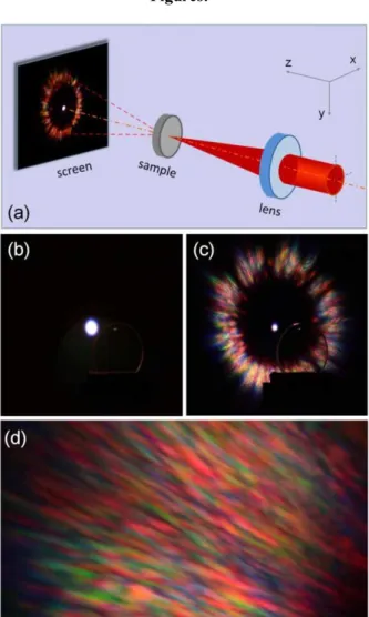
Here we present the first experimental investigation on the laser pulses evolution in the spatial and spectrum domain during laser ablation of transparent materials. Radiation patterns in the form of an ellipse and a ring with large opening angle (~ 100º) are observed, in addition to the directly transmitted laser beam. The elliptic radiation shows a laser polarization-dependent orientation while the ring-shaped does not. More interestingly, the ring-shaped radiation consists of numerous colored needle-like sub-structures with radial orientation. Owing to its spatial and spectral properties, we name this ring-shaped radiation “ciliary white-light” (CWL). We demonstrate the universality of the CWL with respect to the nature of materials (14 transparent media) and laser parameters (polarization states, pulse duration, and focusing geometry). This phenomenon, carrying abundant structural information of the ablation site, provides a real time in-situ observation of laser ablation on transparent materials. Figure 1(a) presents a schematic of the experiments. A chirped pulse amplification (CPA) system (Thales, Alpha 100) is used as the main laser source. This system delivers 50 fs laser pulses with a maximum pulse energy of 10 mJ at a repetition rate of 100 Hz. Femtosecond laser pulses are focused by different convex focal lenses on the front surface of samples in ambient air. With focal lens of f = 1000 mm, the beam waist is estimated to be 91 m. The polarization state of the laser pulses can be changed with a /2 or a /4 wave plate before the lens. The sample is
mounted on a mechanical 3-dimensional translation stage to insure a fresh site after each series of laser shots. A quasi-transparent tracing paper serving as a diffusing screen is installed 23 mm after the sample incident surface. A charge coupled device (CCD) camera captures the laser emission pattern on the screen.
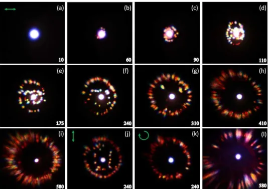
For horizontally polarized laser pulses with energy of Ein = 15 J, a stable, on axis, white light spot is observed on the screen even up to 200,000 laser shots (Fig. 1(b)). This white-light, also referred as supercontinuum emission, has been exploited in many applications such as laser spectroscopy and optical parametric chirped pulse amplification [14, 15]. Interestingly, beyond a threshold laser energy of Ein = 55 J, a new phenomenon becomes apparent with increasing laser shot numbers N. Figure 2 presents the result for Ein = 210 J. After N = 60, the stable white-light spot breaks up and a large number of flickering, colorful speckles appear around the central spot. With the further accumulation of laser shots, these colorful speckles self-organize into two structures: an inner ellipse and an outer ring (Fig. 2(c)-(f)). After 175 laser shots, the ellipse gradually disappears while the outer ring dominates (Fig. 2(e)-(i)). The ring-shaped radiation becomes quite stable after about 410 shots. It exhibits a divergence angle of about 100º, 9 times larger than the central light conical emission (Fig. 2(i)). In this stable state, the central white-light contains only 18.9% (18 J) of the total transmitted laser energy (95 J), indicating that 81.1% of laser energy is now contained in the CWL.
Several features are worth noticing in the above process. First, both the outer ring and inner ellipse structure become larger upon increase of laser shots. Fig. 3(a) shows their opening angles as a function of N. Second, the orientation of the inner ellipse depends on the laser polarization. With vertically polarized laser pulse, this ellipse orientates vertically (Fig. 2(j)). On the other hand, we observed no inner elliptic with circular polarization (Fig. 2(k)). Third, the ring-shaped radiation consists of numerous colorful needle-like rays, which are radially oriented (Fig. 1(c)-(d), Fig. 2(h)-(i)). This structure is found with linearly, circularly, and elliptically polarized laser pulses. The spectrum of this needle-like radiation is presented in Fig. 3(b), together with those of the central white-light and the incident laser pulse. The needle-like rays exhibit a similar spectrum to the central white-light, being significantly broadened compared to the incident laser.
More importantly, we found the CWL in a large number of transparent materials including 4 optical glasses (fused silica, Corning glass, BK7 glass, Pyrex), 6 optical crystals (Quartz, CaF2, MgF2, BaF2, Sapphire, KDP) and 4
transparent polymers (polymethyl methacrylate (PMMA), polyimide (PI), polycarbonate (PC), allyl diglycol carbonate (CR-39)). For example, the result for CaF2 after 580 shots is presented in Fig. 2(l). The thickness of the
various samples varies from 1.5 mm (Corning glass) to 9 mm (KDP) and we found that the CWL phenomena are similar with fused silica samples of different thickness (3 mm and 7 mm). However, the appearance of the ellipse radiation is sensitive to the nature of materials and the laser energy, a fact that requires a future systematic study. We therefore mainly focus on the CWL in this article. We also demonstrated the generality of CWL with respect to laser pulse duration and focusing geometry. For pulses of 500 fs and 1 ps duration with sufficient energy, we observed similar phenomenon as presented in Fig. 2. We changed the 1000 mm lens to 500, 200, 100, 50, 25 mm and always observed CWL emission from fused silica sample.
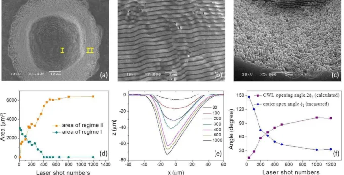
In the following, we propose an explanation for this spectacular phenomenon. We noticed that visible surface damage on the sample is produced once the incident laser energy exceeds the threshold for CWL generation. This indicates the CWL is closely related to the surface damage. For examination of the damage morphology, the sample is observed with a scanning electron microscope (JEOL JSM 6300) after being cleaned in ultrasonic methanol bath and coated for better surface conductivity. Figure 4(a) presents the damage morphology corresponding to N = 240 shots for horizontal laser polarization. There are two regimes with distinct features. Scanning electron microscope (SEM) images of those regimes are shown in Fig. 4(b) and Fig. 4(c). Well-aligned periodic ripple structures cover the central area (regime I), while the periphery is covered by irregularly distributed submicron rods and particles (regime II). Laser induced periodic surface structures (LIPSS) have attracted growing research interests since their discovery 40 years ago [16-19]. Here the ripple structure is parallel to the laser polarization (Fig. 4(b)), referred to as c-type ripple in the literature[16, 17].
We systematically examined laser damage on fused silica as a function of pulse numbers. It was found that after 5 shots, the damage site is entirely covered by the LIPSS. With increasing laser shots, the LIPSS on the peripheral area disappears progressively towards the center while it transforms into regime II. Further laser shots finally lead to disappearance of the central LIPSS. Figure 4(d) shows the dependence of the central and peripheral damage areas on the number of laser shots.
The simultaneous disappearance of the central LIPSS and of the inner ellipse-shaped pattern around 400 shots (Fig. 2(g)-(h) and Fig. 4(d)) suggests that the latter origins from the LIPSS. In fact, a similar effect was observed in a reflected geometry on metal surfaces with a continuous probe laser [16]. This naturally explains the polarization dependence of the orientation of the inner elliptic radiation. The underlying physical mechanism is that the direction of the LIPSS depends on the laser polarization [16-19]. For circularly polarized laser, no well defined LIPSS is generated. This agrees with the fact that no inner ellipse-shaped radiation is recorded in the corresponding case (Fig. 2(k)).
We further examined the damage profiles with a profilometer (Dektek 150). The results are presented in Fig. 4(e). The damage craters deepen progressively with successive laser shots. After about 400 shots the depth of crater becomes saturated, mainly due to the reduction of laser intensity caused by the increase of the lateral surface of the crater irradiated by the laser pulse. In the presence of the crater structure, the laser beam is expected to diffract. Considering the model of a conical crater sketched in Fig. 5(a), the relationship between the opening angle 25 of a
collimated incident beam and the crater apex angle 1 can be obtained as:
1 1 0 1 1 5 0 2 sin arcsin 2 sin sin n n n n . (1)Here n0 and n1 are the refractive index of air and the fused silica sample respectively. For quantitative analysis, we
plot in Fig. 4(f) the measured apex angle 1 of the crater, as well as the corresponding calculated opening angle 25
based on Eq. (1). The calculated results agree well with the measured opening angle of the CWL (Fig. 3(a)), indicating that the opening of the CWL is due to the gradual shape transformation of the crater under successive laser shots.
Based on these understandings, we performed numerical simulations of the beam propagation through the sample to obtain insight into the formation of such needle-like structure of the CWL. We take a spatial Gaussian beam A(x, y) containing a flat spectrum ranging from 500 nm to 1000 nm as incident laser, for simplicity. The measured crater spatial profile P(x, y), and the SEM surface morphology S(x, y) corresponding to the stable state (N > 500) are considered to impart spatial phases on the incident beam. For the sake of numerical feasibility, we obtained the radiation pattern at infinity by taking Fourier transformation of each incident spectrum component modulated by these spatial phases. By adding up the radiation patterns of each spectrum component assigned a false-color, the total radiation pattern in the far field F(kx, ky) is obtained as
nm nm y x y x k Ax y ik n n Px y S x y d ik x k y dxdy k F 1000 500 0 1 , , exp exp , , , (2) wherek
2
is the wavenumber in air and
d
is the modulation depth of the ablated surface. The opening angle is related to the wavevector as
x,y arcsin
n1kx,y k
. In the simulation, we tested different modulation depths and found that d1mproduced result most close to our experimental observation, which is presented in Fig. 5(b). It clearly shows the radially oriented needle-like structure, in good agreement with the measurement (Fig. 2(i)). Therefore, it confirms the CWL origins in the diffraction of the laser generated white-light on the damage crater covered by submicron structures.Based on the above simulation, we can now explain the formation of this radially elongated needle-like feature in an intuitive manner. Due to the strong nonlinear interaction of the laser pulses and the surface, the incident femtosecond pulse evolves into a broadband white-light, as presented in Fig. 3(b). At the same time, this white-light diffracts on the damage crater covered by numerous submicron structures. As a result of diffraction, each spectrum component exhibit an identical speckle radiation pattern in the far field, expect for a spatial scaling factor related to the wavelength. The superposition of a large number of identical patterns with continuously varying spatial scale naturally leads to a radially elongated needle-like structure. This is similar to the so-called ciliary corona phenomenon presented in our human eye vision system. In the night time, most people see a radiating pattern of numerous fine, slightly colored needles of light around bright lights against dark background [20]. The effect was attributed to the presence of specific distributions of small particles in natural eyes, a counter-part of the sub-micron random features on the damage crater in our experiments.
With the underlying mechanisms identified, this optical phenomenon then provides a real time in-situ observation of the laser ablation process. First, the appearance or not of the CWL indicates whether observable damage (by SEM)
occurs on the sample surface after successive laser irradiation. Second, the apex angle of the damage crater can be easily deduced from the opening angle of the CWL, based on Eq. (1). Finally, the species of the sub-wavelength structure (regime I and II) can be identified in-situ from the distribution of the white-light because the correspondence between the optical radiation pattern (CWL and the elliptic ring structure) and the nature of the damage morphology has been established.
In conclusion, we observed a universal novel phenomenon at the frontiers of nonlinear optics and material science, named as ciliary white-light, during laser ablation on transparent materials. This CWL features as a ring-shaped irradiation consist of numerous needle-like rays which are radially orientated. In addition to the CWL, another polarization-dependent ellipse-shaped radiation pattern was observed. We found that the CWL emission is generic with respect to laser parameters and the nature of materials while the ellipse-shaped radiation is not. We interpret the formation of CWL and the pulse evolution in terms of nonlinear diffraction of the laser pulse on the damage crater covered with different kinds of laser-induced surface nanostructures. Calculations and simulations agree well with the observations. This optical phenomenon carries rich structural information of the surface damage, providing a real time in-situ observation of the laser ablation process.
Acknowledgments: The authors thank M. Durand, J. Gotties, A. Santos, R. J. Hui, and J. Q. Wu for providing
various samples, B. Reynier, A. Van Herpen, P. Riberty, and J. Carbonnel for technical help, K. Plamann, S. H. Chen, B. Prade, M. Q. Ruan, Z. B. Liu, H. L. Xu for stimulating discussion. The project has been partially funded by Contract No. ANR-2010-JCJC-0401-01.
Corresponding authors: yi.liu@ensta-paristech.fr and andre.mysyrowicz@ensta-paristech.fr.
References:
[1] J. P. Anthes, M. A. Gusinow and M. K. Matzen, Phys. Rev. Lett. 41, 1300 (1978). [2] C. Phipps, Laser ablation and its applications, (Springer, New York, 2007).
[3] A. Miotello and P. M. Ossi, Laser-surface interactions for new materials production: Tailoring Structure and
Properties, (Springer, Berlin, 2009).
[4] R. R. Gattass and E. Mazur, Nature Photon. 2, 219 (2008). [5] F. Liao, et al. Opt. Lett. 35, 3225 (2010).
[6] F. Dausinger, F. Lichtner and H. Lubatschowski, Femtosecond technology for technical and medical
applications (Springer, Berlin, 2004).
[7] K. Plamann, et al., J. Opt. 12, 084002 (2010). [8] H. B. Zeng, et al., Adv. Fun. Mat. 22, 1333 (2012).
[9] J. C. Miller and R. F. Haglund, Laser ablation and desorption, (Academic Press, New York, 1998). [10] A. Nevin, P. Pouli, S. Georgiou and C. Fotakis, Nature Mat. 6, 320(2007).
[11] S. Siano and R. Salimbeni, Acc. Chem. Res. 43, 739(2010).
[12] S. I. Anisimov and B. S. Luk'yanchuk, Physics-Uspekhi, 45, 293(2002). [13] B. H. Christensen and P. Balling, Phys. Rev. B 79, 155424 (2009). [14] R. Butkus, et al., Appl. Phys. B 79, 693 (2004).
[15] A. Couairon and A. Mysyrowicz, Phys. Rep. 441, 47 (2007).
[16] J. F. Young, J. S. Preston, H. M. Van Driel, and J. E. Sipe, Phys. Rev. B 27, 1155 (1983). [17] G. Seifert, et al., Appl. Phys. A 81, 799 (2005).
[18] V. R. Bhardwaj, et al., Phys. Rev. Lett. 96, 057404 (2006).
[19] A. Y. Vorobyev, V. S. Makin and C. Guo, J. Appl. Phys. 101, 034903 (2007).
Figures:
Fig. 1. (a), Experiment setup. (b), White-light generated by pulses of energy Ein = 15 J. (c), Ciliary white-light generated by pulses of 210 J. In (b) and (c), scattering on the front surface of the sample is also visible. (d), Magnified structure of the CWL at the top-left section.
Fig. 2. (a)-(i), Laser emission patterns as a function of laser shot numbers for horizontally polarized pulses. The
number of laser shots is indicated in each panel. The laser pulse (210 J) is focused by a lens with f = 1000 mm. (j) and (k), Laser emission patterns for 240 laser shots with vertical and circular laser polarizations. Other conditions are the same as in (a). (l), Emission pattern obtained with CaF2 for 580 laser shots, with other experimental
conditions identical to (a). The full view angle of the image is 120º × 117.5º with respect to the laser ablation spot on the sample, for horizontal and vertical directions.
Fig. 3. (a), Opening angles of the CWL and the inner ellipse-shaped radiation (vertical direction) as a function of
laser shot numbers. (b), Spectra of the CWL, the central white-light, and the incident laser pulses. The CWL spectrum is an average over 10 different positions on the ring structure.
Fig. 4. (a), Morphology of the damage produced with 240 laser shots observed with SEM. Regimes I and II
represent the central area covered by LIPSS and the peripheral area covered by nanostructures respectively. (b) and (c), Higher resolution SEM image of the centre of regime I and the bottom of the regime II. (d), Evolution of the area of the two regimes. (e), Profiles of the damage produced with successive laser shots. (f), Apex angle 1
determined from (e) and the corresponding calculated opening angle 25 of a collimated beam shot at the damage
Fig. 5. (a), Modeling of the damage crater as a cone and its consequence on an incident collimated beam. (b),