HAL Id: hal-01819258
https://hal.archives-ouvertes.fr/hal-01819258
Submitted on 20 Jun 2018HAL is a multi-disciplinary open access
archive for the deposit and dissemination of sci-entific research documents, whether they are pub-lished or not. The documents may come from teaching and research institutions in France or abroad, or from public or private research centers.
L’archive ouverte pluridisciplinaire HAL, est destinée au dépôt et à la diffusion de documents scientifiques de niveau recherche, publiés ou non, émanant des établissements d’enseignement et de recherche français ou étrangers, des laboratoires publics ou privés.
Human to humanoid motion conversion for dual-arm
manipulation tasks
Marija Tomić, Christine Chevallereau, Kosta Jovanović, Veljko Potkonjak,
Aleksandar Rodić
To cite this version:
Marija Tomić, Christine Chevallereau, Kosta Jovanović, Veljko Potkonjak, Aleksandar Rodić. Human to humanoid motion conversion for dual-arm manipulation tasks. Robotica, Cambridge University Press, 2018, 36 (8), pp.1167-1187. �10.1017/S0263574718000309�. �hal-01819258�
Human to humanoid motion conversion for dual-arm
manipulation tasks
Marija Tomi憇*, Christine Chevallereau ‡, Kosta Jovanović †, Veljko Potkonjak †, and Aleksandar Rodić*
†School of Electrical Engineering, University of Belgrade, Bulevar kralja Aleksandra 73, 11000 Belgrade, Serbia
‡CNRS, LS2N, Ecole Centrale de Nantes, 1, rue de la No, 44321 Nantes, France *Robotics Laboratory, IMP, Volgina 15, 11000 Belgrade, Serbia
SUMMARY
A conversion process for the imitation of human dual-arm motion by a humanoid robot is presented. The
conversion process consists of an imitation algorithm and an algorithm for generating human-like motion
of the humanoid. The desired motions in Cartesian and joint spaces, obtained from the imitation algorithm,
are used to generate the human-like motion of the humanoid. The proposed conversion process improves
existing techniques and is developed with the aim to enable imitating of human motion with a humanoid
robot, to perform a task with and/or without contact between hands and equipment. A comparative
analysis shows that our algorithm, which takes into account the situation of marker frames and the
position of joint frames, ensures more precise imitation than previously proposed methods. The results of
our conversion algorithm are tested on the robot ROMEO through a complex “open/close drawer” task.
KEYWORDS: Motion capture system; dual arm manipulation; imitation algorithms; humanoid robot, motion planning.
1. Introduction
2
learning process is based on the repetition of observed motions. Once a human observes a task being
carried out for the first time, they are usually capable of immediately performing the same action. In
robotics, this process is more complex and can be interpreted in different ways, such as: the imitation
learning process and the motion imitation process [1]. The imitation learning process is aimed at
understanding the characteristics of human motions, based on data collected from multiple observations of
the demonstrated action. On the other hand, the motion imitation process is based on the imitation of
human movements without any analysis of the characteristics of the human motion. In this paper we
consider the latter approach and propose an algorithm based on how the robot imitates human motion, by
utilizing recorded data obtained from a marker-based motion capture system.
Today, there are numerous techniques for recording and analyzing human motions. Human motions can be
tracked by a number of different motion capture systems, such as inertial, optical, magnetic, acoustic or
mechanical. The type of motion capture system used depends on the volume of measurements taken, the
required resolution, the characteristics of the motion recorded and the environment in which the motion is
performed. Acoustic [2], inertial [3] and magnetic [4] motion capture systems are able to record outdoor
and indoor human motions. The most commonly used techniques for recording human movement are
marker-based and marker-less motion capture systems. Comparative analyses of different motion capture
systems are given in references [5-7]. In order to record a 3D model of human motion, including the
position and orientation of the required segments and joints, in this research we used an ART
marker-based motion capture system.
The imitation process can be defined in Cartesian space and/or joint space [8]. In Cartesian space, the
motions of the hands, head, or feet are recorded and a geometric inverse model of the humanoid can be
used to achieve the task. In joint space, the objective is to enable the robot to replicate joint motions of the
3
process and allows for human-like behavior, especially in the presence of a redundant robot. If a human
(or a robot) has to achieve the same task in Cartesian space as another human of different body size, they
have to modify the motion of the joints while keeping the end-effector (hands, feet or head) in the same
Cartesian position. Since the human (or robot) is a kinematic redundant structure, the same end-effector
trajectories are feasible for different joint trajectories. The main idea of the research was to achieve these
joint trajectories so they fit the motion of human joints as much as possible while keeping the required
end-effector motion in Cartesian space. Therefore, joint trajectory tracking was the object of optimization,
while end-effector trajectory tracking was an imposed constraint in the optimization process. It should be
noted that depending on the task being analyzed, various components in Cartesian space can be taken into
account (position, or position and orientation of the hands). In the case of a task that involves contact
between hands and equipment, the position and orientation of the hand should be included as a constraint
in the optimization process, whereas in a task without contact between hands and equipment, following of
the position of the hands is required. In short, to imitate a dual-arm human motion, where the robot
interacts with the environment using its hands and exhibits human-like motion behavior, the imitation
process needs to include mimicking of human motion in the joint and Cartesian spaces.
The human motion imitation problem can be solved at the kinematic or the dynamic level. In Ott et al. [9],
the robot imitated human motions by using dynamic equations. Based on measurements of marker
positions, they define a Cartesian control approach to real-time imitation of a human’s upper body. Virtual
springs connected the measured marker positions and corresponding points on the humanoid robot. Since
additional difficulties arise in the process of motion imitation by a humanoid robot, such as joint velocity
and torque limits, Suleiman et al. [10] also use dynamic equations to formulate a recursive optimization
algorithm for imitating human motion. It permits the imitation of upper-body human motion by using the
physical capabilities (joint, velocities, torques) of a humanoid robot. Huang et al. [11] present an
4
constraints and dynamic stability. Jamisola et al. [12] show modular task-space dynamic formulations for
a dual arm controlled as a single manipulator. They used existing kinematic and dynamics models of each
of the stand-alone manipulators to arrive at the overall dynamics of the single end-effector dual-arm. The
treatment of a dual-arm as a single end-effector manipulator through the use of the relative Jacobian
affords a drastic increase in the null-space dimension and lesser constraints in the task space. This
approach was tested for dual-arm manipulation tasks which did and did not require coordination between
hands.
The human motion imitation problem is addressed at the kinematic level by Ude et al. [13, 14]. They
propose a method for transforming the recorded 3D position of the markers into high dimensional
trajectories of the humanoid robot joints based on twist representation. The human body was modeled as a
scaled model of the humanoid robot. They established relationships between the motion of the robot’s
joints and the motion of the markers by using B-spline wavelets and large-scale optimization techniques.
The method was applied offline to a humanoid robot called DB. Ayusawa et al. [15, 16] propose a
gradient-based method for simultaneous identification of the geometric parameters of a human skeletal
model and calculation of inverse kinematics by using information about the recorded positions of markers.
In order to define the geometric parameters, as segment lengths, and the positions of the markers relative
to the robot segments, they introduced virtual translation of joints. In the present research, the problem of
human motion imitation was studied at the kinematic level.
According to the state of the art of the imitation process, we additionally explored:
• Imitation of the upper-body human motion by the humanoid, where the motion consists of phases without and/or with hand contact with the environment and a transition strategy between these two
5
• An analytical imitation algorithm based on the Jacobian matrix (instead of the standard optimization algorithm presented in our previous research [17]), which is capable of real time
extraction of Cartesian motions and joint motions that can be used by the humanoid.
In the present research, human-to-humanoid motion conversion is divided into two parts. In the first part,
we used the information provided by the motion capture system and analytically defined the imitation
algorithm to acquire the desired motion of the humanoid in the task and joint spaces. The algorithm is
based on the markers positioned on a scaled model of the humanoid (virtual markers), which follow the
motion of markers (real markers) placed on the human. The intermediate use of a scaled model of the
humanoid presented by Ude et al. [14] permits the size of the robot to be adapted to the size of the human
that has accomplished the task and thus to record the coherent joint and Cartesian motions. Since the task
of the imitation algorithm proposed in the present paper is to generate a motion where the hands and the
environment are in contact, precise imitation of the hand motions is important. This imitation algorithm
incorporated not only marker motion but also joint motion measurement, in order to increase the robot’s
imitation accuracy. Instead of twists in our kinematic model, the modified Denavit and Hartenberg (DH)
convention was used to simplify modeling [18]. The imitation algorithm is based on the kinematic
structure of the humanoid and can be used in real time.
In the second part of the conversion, the motion imitation of the scaled robot model was used to generate a
human-like motion on the robot ROMEO in its real size (1.40 m tall) and in the same environments. The
strategy differed depending on whether a contact with the environment did or did not exist during the
studied phase of motion. When there was contact with the environment, the hand motions were defined to
achieve the contact and the robot hand motions had to be the same as those of the human. During the phase
without contact, priority was given to motion that appeared visually close to human motion and was based
6
since they are not constrained by equipment. As such, if contact motion is observed, hand motion in
Cartesian space is perceived as a constraint while joint positions in joint space are the object of the
optimization process. Contrarily, if contact free motion is observed, the optimization process focuses on
both hand motion in Cartesian space and joint positions in joint space, and different priorities can be set.
The approach exploited in this research is elaborated in Section 4. Conversion from human to humanoid
motion is analyzed for a complex task that consists of both types of motion. A transition strategy for
motion with and without contact is introduced. Since the task is motion imitation with contact between
hands and equipment, the technique proposed by Ude is unable to generate these types of motions for the
robot. The advantage of the proposed conversion algorithm over existing algorithms is precise imitation of
the position and orientation of human hand motions, which is necessary to perform the task. The results of
the conversion algorithm were tested on the ROMEO robot in the same environment as that of the human.
The following paragraphs present kinematic parameters and their correlations for each model instance in
the conversation process (human and graphical/digital representation – avatar, scaled model of the
humanoid, and ROMEO). An overview of the entire human-to-humanoid motion conversion process is
provided in Section 2. Each step of the conversion process is explained in detail.
Fig. 1. Models in the human-to-humanoid motion conversation process and related parameters
The conversion process for human-to-humanoid motion imitation is directly related to the transformation
process from kinematic human parameters to those of the humanoid. To that end, three kinematic models
7
model of the ROMEO robot, and kinematic model of the real-size ROMEO robot (see Fig. 1). These
models were represented by their parameters in Cartesian space and joint space, as indicated in Fig. 1. The
conversion process started with the kinematic model of the human body, which was automatically
generated by the motion capture system. This digital/graphical representation of the human body was
denoted as the avatar model. The avatar model contained twenty spherical joints (60 degrees of freedom
(DoFs) in total), to define its kinematic model. The avatar segment sizes which corresponded to those of
the human were estimated by the motion capture system. To enable human motion imitation by a
humanoid robot, ROMEO was selected because it is a humanoid with 37 DoFs, but its segment sizes differ
from those of a human. In order to make a connection between the avatar and the humanoid kinematic
model, an intermediate model, called a scaled model of the humanoid, was defined. The scaled model of
the humanoid had the same kinematic structure as ROMEO (37 DoFs) and the same segment sizes as
those in the avatar model.
The conversion from the avatar to the model of the humanoid in Cartesian and joint spaces was described
by equations, to facilitate understanding of the scaling process. Considering the avatar model, Eq. (1)
relates generalized joint coordinates (q ) and hand position and orientation in Cartesian space: h
h h h
X =J q (1)
For dual-arm manipulation, X represents the position and orientation of both human hands, and h J is the h
Jacobian matrix of the avatar model. The dimension of vector q contains 60 elements that correspond to h
the avatar’s 60 DoFs. However, to enable conversion from the recorded human motion to the generated
ROMEO robot motion, the scaled kinematic model of ROMEO was used to represent the human body
model. To that end, the scaled robot model had 37 DoFs and segment dimensions equal to human. The
8
generating human-like motion of the humanoid in joint space. The marker trajectories and the joint
positions in Cartesian space obtained for the avatar model were translated to the scaled model of the
humanoid. Consequently, this information was input into the imitation algorithm to obtain the human
motion in joint space q . Accordingly, the human hand motions in Cartesian space generated by the sr
scaled model of ROMEO were calculated from the equation:
h sr sr
X =J q (2)
where J is the Jacobian matrix of the scaled model of ROMEO. For humanoid robot control, the joint sr
motion q is useful but the motions of the hand, which are in contact with the environment, are sr
mandatory. Since this information was not directly measured by instrumentation, it was defined via Eq.
(2) based on the joint motion resulting from the imitation process and the Jacobian matrixJ . To arrive at sr
human motion of the humanoid robot ROMEO, joint motion q can be played on the robot. However, the sr
motion of the robot’s hands in Cartesian space, resulting from joint motion q , was defined by the sr
equation:
robot robot sr
X =J q (3)
where Jrobotis the Jacobian matrix of the ROMEO model and Xrobotis the position and orientation of
ROMEO’s hands in Cartesian space. The scaling factors between models of different segment sizes were
integrated through the Jacobian matrices Jrobot and J . The motion of the robot’s hands in Cartesian sr
space (Xrobot) was different from the motion of human hands X since the segment sizes of the human h
and the robot were not the same. Therefore, the motion of the robot’s hands generated in this manner can
only be used for a motion without contact between hands and equipment. If the motion involves such a
9
robot h
X = X (4)
Thus, in contact tasks where the motion of the robot’s hands has to be the same as of human hands in
Cartesian space, and where, additionally, human motion needs to be imitated in joint space, the
generalized robot coordinates (qrobot) can be defined by the inverse kinematic algorithm (5). The inverse
kinematic algorithm is the object of optimization, as explained in Section 4.
( )
robot robot h robot robot sr
q =J+ X + −I J+ J q (5)
Here, Jrobot+ represents the pseudo-inverse of the matrix Jrobot and I is the identity matrix.
The paper is organized as follows. Section 2 presents the conversion steps from human to humanoid
motion and the basic characteristics of the robot and the capture motion system. Section 3 proposes our
imitation algorithm that converts data obtained from the capture motion system into joint trajectories of
the scaled robot model. The imitation process starts with the definition of the humanoid robot kinematic
model. The motion generation algorithm for the real robot ROMEO, which takes into account the output
from the imitation algorithm, is given in Section 4. The conversion process was tested for the dual arm
“open/close drawer” task and the results are presented in Section 5.
2. Conversion Steps from Human to Humanoid Motion
Regardless of the motion capture system, the conversion from human to humanoid motion can be
represented in four steps: the first step is recording of human motion; in the second, a digital/graphical
representation of the human body (avatar) is defined according to the data acquired by the motion capture
system; in the third step a human-size kinematic model of the robot (scaled humanoid model) is defined and
10
fourth step concerns the generation of ROMEO’s motion (with and without contact), using the output from
the imitation algorithm. An overview of the conversion from human to humanoid motion is given in Fig.
11
12
The motion capture system is able to recognize and find relations between the actor’s body segments in
consecutive frames and provide a graphical representation of the actor (avatar) in a virtual environment
[19] (see Fig. 2, step 1). The kinematic model of the avatar graphically represented the human body and
included 60 DoFs (20 joints with 3 DoFs per joint). Since the kinematic model of the humanoid, which
was used in the imitation process, had 37 DoFs in total (fewer DoFs than the avatar), the model of the
avatar could not be used directly and a reduced model that enabled human to humanoid motion replication
had to be adopted.
An adult human body has 206 bones linked by different types of joints, which can be flexible. The
imitation process needs to be based on the effective kinematic model of the humanoid robot, consistent
with its joint mobility and size. Many humanoid robots of a size close to that of a human have several
DoFs, e.g. at least 7 DoFs per arm and 6 DoFs per leg (see Fig. 3). A humanoid robot with these
characteristics, such as the humanoid robot ROMEO, can be used for accurate human motion imitation.
The closer the kinematic model of the humanoid is to the model of a human as regards the size, joint limits
and kinematic model, the better the imitation.
The transformation of the kinematic model of the avatar to the model of ROMEO is described on two
levels. At the first level, the simplification of the kinematic model was taken into account, so the kinematic
model of the avatar (which had 60 DoFs) was reduced to the model of the robot ROMEO (37 DoFs). This
kinematic model, which had the same segment size as that of the avatar model and the number of DoFs
equal to those of ROMEO, was defined as a scaled model of ROMEO. Therefore, the scaled model of
ROMEO was used in the imitation algorithm to define human motion in joint space. The output of the
imitation algorithm was coherent motions in joint space and Cartesian space for the scaled model of
ROMEO. At the second level, the difference in body segments between the human and ROMEO was
13
implemented with the algorithm for human-like motion generation. At this level, the motion defined in
joint and Cartesian spaces provided by the imitation algorithm was non-coherent (using the real size of
ROMEO) and the algorithm favored the motion defined in joint or Cartesian space depending on whether
the task did or did not involve contact with the environment.
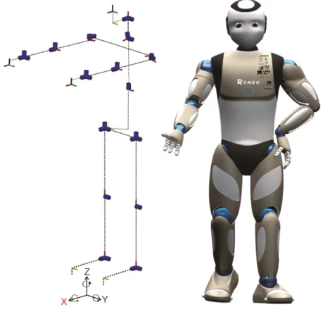
2.1. Robot ROMEO
The humanoid robot ROMEO has been developed by Aldebaran Robotics (see Fig. 3). ROMEO is 1.4
meters tall and has 37 DoFs, including 7 DoFs per arm, 6 DoFs per leg, 2 DoFs for each eye, 1 DoF for
each foot, 2 DoFs for the neck, 2 DoFs for the head, and 1 DoF for the spine [20].
14
Dual arm manipulation of the robot was analyzed in this research. To that end, an extended kinematic
model of ROMEO’s upper body was used. The model contained 19 DoFs and an additional 3 DoFs in the
trunk, which emulated leg motion (3 prismatic (see Fig. 4)).
2.2. ART Motion Capture System
The ART motion capture system consists of a hybrid suit of 17 sets of markers relative to the feet, shins,
thighs, shoulders, upper arms, forearms, hands, head, hip, back, and torso (see Fig. 2). A set of 8 infrared
(IR) cameras is used to record markers motions. The motion capture hardware is supported by DTrack
software and ART Human software is used for tracking and reproducing the motion of the actor in a virtual
environment. DTrack software acquires 2D marker positions using information from each IR camera and
provides the transformation matrices of each marker (position and orientation of the marker) relative to
different local frames attached to the body parts with respect to the global reference frame. ART Human
software uses the information provided by DTrack and provides a direct link between motion of the human
subject and motion of the 3D graphical model of the human (avatar) in real-time. ART Human estimates
the locations of the human joint frames and the human segment size using marker information. The digital
human representation, the avatar model, is created in this manner [19]. The flowchart showing how the
motion capture system works is depicted in Fig. 2, step 2. The sampling frequency for data acquisition is
set to 100Hz.
3. The Imitation Process
The information provided by the motion capture system can be used to define the characteristics of the
15
has been on estimating a kinematic model of the human body using data obtained by the motion capture
systems [21, 22]. In this research, we used data obtained by the ART motion capture system to scale the
kinematic model of the robot ROMEO to the characteristics of the actor.
The motion capture system always automatically generates the avatar model as a 3D graphical
representation of the human. Each avatar joint is represented as spherical. Therefore, the avatar model has
60 DoFs to represent human motion. The kinematic model of ROMEO was used to imitate human motion
in joint space. Therefore, the kinematic representation of the human body was reduced from the avatar
model to the kinematic model of ROMEO. Since the information obtained from the motion capture system
(such as the position and orientation of real markers and the position of joints) is defined according to the
model of the human-size avatar performing the recorded action, the kinematic model of ROMEO was
scaled to the size of the human. In that manner it was possible to calculate human motion in joint space.
An initialization process was introduced with the aim of defining the initial configuration of the actor and
to scale the size of ROMEO to the size of the actor and attach virtual markers to the scaled model of
ROMEO. The initial configuration of ROMEO (see Fig. 4(a)) is proposed as the initial configuration of
the actors (arms horizontally extended forward, with palms facing the floor (see Fig. 4(b))), because it is
16
Figure 4. The scaling process: (a) extended kinematic model of the robot ROMEO in its basic configuration; (b) extended kinematic model of ROMEO scaled to the dimensions of a human in the initial
configuration, with markers and marker frames
Since the kinematic model of ROMEO was taken as the kinematic model of a human, the size of the
robot’s segments had to be scaled to the size of the actor’s limbs. The dimensions of the human segments
were calculated by taking the mean Euclidian distance between two adjacent joints and using several
samples from the recorded data, when the actor retained the initial configuration. The dimensions of the
paired segments located on the left and right sides of the body, assumed to be identical, were calculated by
taking the mean value of the estimated segment dimensions on the right and left sides for each actor. The
scaling factor SF for each segment was calculated as the ratio of the actor segment length Lhuman to
ROMEO segment length Lrobot, human
robot
L SF
L
=
The position of the real marker relative to the corresponding proximal frame of the actor’s joint and the
dimensions of the segments were calculated and assumed constant in the scaled model of the humanoid. In
reality, this quantity varies during motion of the actor due to unmodeled joints of the human and motion of
17
and the real markers attached to the shoulders (see Fig. 5). Although the markers are firmly attached to the
body segments, the distance between a real marker and its proximal joint is not constant due to the motion
of the skin. This phenomenon is the most obvious in the case of hand and shoulder markers. An error
occurs and a perfect imitation of human motion by the scaled kinematic model of the humanoid is not
possible. Virtual marker fames were defined according to real marker frames in the initial configuration,
during the initialization process. Details about the calculation of virtual markers frames are provided in the
Appendix. The imitation algorithm was used to calculate the joint configuration of the scaled model of
ROMEO, in order to minimize the matching error between the virtual and real markers and the matching
error between the joint positions of the human to the joint positions of the scaled model of ROMEO.
Figure 5. Displacement of the shoulders and real markers attached to the shoulders during motion.
3.1. Imitation algorithm for the scaled model of the robot
In this section, an analytical imitation algorithm based on the Jacobian matrix capable of real time
extraction of Cartesian motions and joint motions is introduced. The imitation algorithm was formulated
as an optimization algorithm (6), which calculated the generalized coordinates of the joints qimitation i(t )
for the scaled model of ROMEO, for each time sample t ,i with i∈
[
1 N]
, where N is the number of time18
( )
( ) min imitation i q q t = ζ (6)The criterion function ζ, which should be minimized, was comprised of the error between the position of the frames attached to the actor joint Pajand those of the scaled model of the humanoid Prj; the error
between the position of the real marker frames Prmand virtual marker frames Pvm; and the error in
orientation between the real marker frames Rrm and virtual marker frames Rvm in the way proposed in
Eqs. (7) and (8). Since the precision of orientation measurement was lower than that of position
measurement, and the orientations of the proximal segments were implicitly taken into account via their
effect on distal joint positions and markers, the orientations of the proximal frames were disregarded in the
minimization criterion. Only the orientations of the distal segments were included.
The optimization criterion is:
2 ( , )t qi ζ = ε (7) where
(
)
(
)
(
)
(
)
(
)
(
)
( ) ( ) ( ) ( ) ( , ) ( , ) ( , ) ( ) ( ) ( ) ( ) LeftHand RightHand LeftHand LeftHand RightHand RightHand rm i vm aj i rj rvm i i rvm i aj i rj aj i rj P t P q P t P q e t q t q e t q P t P q P t P q ⎡ α − ⎤ ⎢ ⎥ ⎢ β − ⎥ ⎢ ⎥ ⎢ ⎥ γ Δ ⎢ ⎥ ⎢ ⎥ ε = ⎢ ⎥ γ Δ ⎢ ⎥ ⎢ ⎥ ⎢ δ − ⎥ ⎢ ⎥ ⎢ ⎥ δ − ⎢ ⎥ ⎣ ⎦ (8)where α ,β, γ and δ are the weighting factors for the errors in marker positions, joint positions, hand marker orientations, and hand joint positions, respectively;Prm i( )t and Paj i( )t are the vectors of the
recorded real marker positions and proximal actor joints at time sample ti, respectively; Pvm( )q and
( )
rj
P q are the vectors of the positions of the virtual markers and proximal robot joints in the current joint
19 ( ) ( ) ( ) ( ) ( ) ( ) ; ( ) ( ) ( ) ( ) LeftUpperArm LeftUpperArm RightUpperArm RightUpperArm LeftForeArm LeftForeA RightForeArm LeftHand RightHand rm i vm rm i vm rm i vm rm i vm rm i rm i rm i P t P q P t P q P t P P t P q P t P t P t ⎡ ⎤ ⎢ ⎥ ⎢ ⎥ ⎢ ⎥ ⎢ ⎥ ⎢ ⎥ =⎢ ⎥ = ⎢ ⎥ ⎢ ⎥ ⎢ ⎥ ⎢ ⎥ ⎣ ⎦ ( ) ( ) ( ) ; ( ) ; ( ) ( ) ( ) ( ) ( ) ( ) LeftShoulder LeftShoulder rm RightShoulder RightForeArm LeftElbow LeftHand RightElbow RightHand aj i rj aj i aj i rj vm aj i vm aj i vm P t P q P t P t P q P q P t P q P t P q ⎡ ⎤ ⎢ ⎥ ⎢ ⎥ ⎡ ⎤ ⎢ ⎥ ⎢ ⎥ ⎢ ⎥ ⎢ ⎥ ⎢ ⎥ =⎢ ⎥ = ⎢ ⎥ ⎢ ⎥ ⎢ ⎥ ⎢ ⎥ ⎢ ⎥ ⎢ ⎥ ⎣ ⎦ ⎢ ⎥ ⎢ ⎥ ⎣ ⎦ ( ) ( ) ( ) ( ) RightShoulder LeftElbow RightElbow rj rj rj q P q P q P q ⎡ ⎤ ⎢ ⎥ ⎢ ⎥ ⎢ ⎥ ⎢ ⎥ ⎢ ⎥ ⎢ ⎥ ⎣ ⎦ ( ) LeftHand aj i
P t and PajRightHand( )ti are the positions of the left and right actor hand joints at time sample ti,
respectively; PrjLeftHand( )q and PrjRightHand( )q are the positions of the left and right robot hand joints in the
current joint configuration q; and ΔervmLeftHandand ΔervmRightHand are the orientation errors between the
real and virtual markers attached to the left and right hands (distal markers) at time sample ti and in joint
configuration q, respectively. The orientation errors were represented in terms of quaternions. The
rotation matrices, RrmLeftHand( )ti and RvmLeftHand( )q (which express the real and virtual marker orientations
of the left hand, respectively), can be rewritten in terms of quaternions as
1 ( ) 2 ( ) 3 ( ) 4 ( )
LeftHand LeftHand LeftHand LeftHand LeftHand
rm rm i rm i rm i rm i
Q = ⎢⎡Q t Q t Q t Q t ⎤⎥
⎣ ⎦ and
1 ( ) 2 ( ) 3 ( ) 4 ( )
l LeftHand LeftHand LeftHand LeftHand
vm vm i vm i vm i vm i Q = ⎢⎡Q t Q t Q t Q t ⎤⎥ ⎣ ⎦ , respectively where 1 ( ) rmLeftHand QrmLeftHand ti η = , 2 ( ) 3 ( ) 4 ( )
rmLeftHand LeftHand LeftHand LeftHand
T rm i rm i rm i e = ⎣⎡Q t Q t Q t ⎤⎦ , vm 1 LeftHand( ) LeftHand Qvm q η = , and 2 ( ) 3 ( ) 4 ( )
vmLeftHand LeftHand LeftHand LeftHand
T
vm vm vm
e = ⎣⎡Q q Q q Q q ⎤⎦ . The orientation error
LeftHand rvm e Δ was calculated using Eq. [22]: ( , ) ( ) ( ) ( ) ( ) ( ( )) ( )
LeftHand vmLeftHand rmLeftHand
rmLeftHand vmLeftHand rmLeftHand vmLeftHand
rvm i i i i e t q q e t t e q S e t e q Δ = η ⋅ − η ⋅ − ⋅ (9)
where S( )⋅ is the skew-symmetric operator of the vector.
20
The minimization criterion is quadratic. The configuration at time sample ti can be expressed as the
configuration at time ti−1 plus the change in configurationΔq. Thus, the criterion can be expressed as a
function of Δq:
1 1 1
( , )t qi ( ,t qi imitation i(t−) q) α( ,t qi imitation i(t− )) β( ,t qi imitation i(t−)) q
ε = ε + Δ = ε +ε Δ (10)
where vector εα( ,t qi imitation i(t−1)) can be evaluated based on Eq. (8), and matrix εβ( ,t qi imitation i(t−1)) based
on its derivative. The analytical expression for Δq is deduced for the optimality condition
(
2)
1 ( , ( ) ) 0 i imitation i t q t q q q − ∂ ε + Δ ∂ζ = = ∂Δ ∂Δ , so that: 1 1 ( ,i imitation i( )) ( ,i imitation i( )) q β t q t− + α t q t− Δ = −ε ⋅ε (11)where εβ( ,t qi imitation i(t−1))+represents the pseudo inverse of the matrix εβ( ,t qi imitation i(t−1)). More details
about vectors εα( ,t qi imitation i(t−1)) and matrix εβ( ,t qi imitation i(t−1))are provided in the Appendix.
Factors α ,β, γ and δ in the imitation algorithm assigned different desired levels of precision for joint and marker tracking. The values of the weighting factors were set heuristically. Since contact tasks require
high precision of the hand positions and orientations in Cartesian space, weighting factors δ (hand position
weighting factor) and γ (hand marker orientation) had significantly higher values than other factors.
However, the weighting factor γ should be set to slightly less than δ, since orientation measurement
precision is lower than that of position measurement. The positions of proximal (shoulder and elbow)
joints in Cartesian space is less important than the Cartesian position of the hand joints, but they still have
a significant effect on the similarity between recorded human motion and generated humanoid motion.
The associated weighting factor was β. The similarity between the recorded human motion and the
generated humanoid motion was depicted by marker position as well, but with the aim of reducing the
effect of skin motion (which directly influences the motion of the markers), weighting factor α had to be
21 and δ=20.
The actor motion in Cartesian space X was re-calculated using h qimitation i(t ) and the direct geometric
scaled model of the ROMEO robot. Furthermore, the orientation of the hands’ joints, which was unknown
from the data obtained by the motion capture system, was also calculated in this manner. A comparative
analysis of the recorded hand positions and the position calculated by the imitation algorithm is given in
Section 5.
4. From Imitation Results to Motion of Robot ROMEO
The motion obtained with the previously described imitation algorithm could not be used directly by the
humanoid robot ROMEO because joint limitations had not been taken into account. If joint motion
( )
imitation
q t is used directly by ROMEO, the motion in Cartesian space will not be preserved and thus
contact with the environment will not be achieved. On the other hand, if Cartesian motion is used, human
skill will not be preserved. Therefore, we propose different strategies depending of the existence of
contact with the environment or not. A contact with the environment is assumed to exist via the hands of
the robot. The case of contact with another body part may be considered in a similar way. A transition
strategy will also be proposed between the contact and no contact phases.
During a motion with contact, the motion of the actor’s hands was constrained by the characteristics of the
equipment. In [24], we elaborated the types of contact constraints and the corresponding mathematical
representations. Here we studied the case in which the robot should do the task in the same environment as
that of humans, with the same type of contact. The moment when the robot’s hands established contact
with the equipment was calculated using the hand positions of the scaled model of the robot and the known
position of the equipment. To that end, the hand coordinates of the scaled robot model and the equipment
coordinates were represented in the same referent frame. For the phase of contact, the robot’s hands should
22
performing the task by the robot is that the trajectories of the actor’s hands (for the phase of contact) are
within the workspace of the robot. The workspace of ROMEO was defined according to the robot segment
size and the joint limits as proposed in [25, 26]. If this condition is satisfied, when the robot is initially in
the same place as the actor, the actor’s motion will be easily achieved by ROMEO. Otherwise, a new
initial position and orientation of the robot need to be calculated for the task to become feasible. In the
latter case, the transformation matrix that describes the displacement of the robot is taken into account, in
order to modify the desired motion of the robot’s hands accordingly.
4.1. Inverse kinematic algorithm as a tool for human-like motion generation
The human motion imitation process requires the robot to be able to perform a task like a human. Since the
structure of ROMEO is designed with redundant features, the same motion as that of human hands can be
obtained for different arm configurations. By using the inverse kinematic algorithm, the recorded human
joint motion can be imitated by ROMEO. The minimized difference between the current joint trajectories
( )
robot
q t and joint trajectories qimitation( )t obtained with the imitation algorithm for the scaled robot model
2
( ) ( )
robot imitation
q t −q t was included in the inverse kinematic algorithm as an additional criterion:
1 1
( ) ( ) ( )( ( ) ( ))
( ) ( ) ( )
robot i robot i robot robot robot i imitation i
robot i robot i robot i
dq t J dX t I J J q t q t q t q t dq t λ + + − − = − − − = + (12)
where Jrobot+λ is the damped least-square inverse of the Jacobian matrix Jrobot and damping factor
0.003
λ = (see [27]), which was introduced with the aim of solving the discontinuity problem of the
pseudoinverse solution for a singular configuration; Jrobot+is the pseudo-inverse of the Jacobian matrix
robot
J of ROMEO, calculated for the robot size; I is the identity matrix; and dX t( )i is the position and
orientation variation between the desired trajectories of the robot’s hands Xrobot id ( )t and the current
23 using the real size of the robot:
1
( )i robot id ( ) robotc ( robot i( ))
dX t = X t −X q t− (13)
The desired trajectories of the robot’s hands Xrobotd have to be the same as the motion of human hands in
Cartesian spaceX . The joint limits were included in the inverse kinematic algorithm by using the internal h
clamping loop that checked and removed the joints that reached their upper or lower joint limits min
robot
q and
max
robot
q , respectively. If a joint reached the limit, the joint value was clamped to the limit value. The elements
of the Jacobian matrix J and identity matrix I related to the clamped joint were set to zero. In this
manner, any further motion of the clamped joint is prevented. The inverse kinematic algorithm continues
to initiate other joints in order to reach the desired values for the hands. The inverse kinematic algorithm
with a clamping loop is explained in detail in Baerlocher et al. [28].
The primary task of the inverse kinematic algorithm was to follow the desired hand trajectoriesXrobot id ( )t .
If motion involved contact between hands and equipment, the robot needed to use the same equipment and
manipulate it in the same way as a human. The desired motions of the robot’s hands were defined in the
imitation algorithm, calculating the hand position and orientation using qimitation( )t and the direct
geometric model of the scaled ROMEO. However, it is important to note that qimitation( )t was defined for
a scaled model of the robot and that Jacobian matrix J used here was calculated for the real size of
ROMEO. Parameters qimitation( )t and Xrobot id ( )t were not consistent, thus the secondary task was not
achieved andqrobot( )t differed from qimitation( )t .
4.2. Motion of robot hands without contact
A robot is not able to simultaneously follow recorded hand and joint motions since the robot size and joint
24
preferable to follow human joint motions rather than human Cartesian motions, in order to express human
skills.
However, to keep the same control approach with and without contact with the environment, and to take
into account the joint limits, we used a slightly modified Eq. (12):
( )
1( ) c ( ) c ( ( ))
i robot imitationModif i robot robot i
dX t = X q t −X q t− (14)
where qimitationModif
( )
t is the modified value of i qimitation( )t , since the value of qimitation( )t can be outsidethe robot’s joint limits. The modification was implemented using the algorithm proposed by Safonova et al.
[29]. In this manner, c (
( )
)robot imitationModif i
X q t was inside the workspace of the robot and the desired motion
in the joint and Cartesian spaces was coherent and consistent with the dimensions of the humanoid robot.
The joint limits were also taken into account.
4.3. Transition strategy connecting motions with and without contact
For a motion with or without contact of the hands with the environment, we proposed the algorithm given
by Eqs. (12) and (14). The difference between the two cases is in the manner used to define the desired
Cartesian motion. As a consequence, we propose a transition strategy based on rescaling the size of the
robot to the size of the actor. The transition strategy starts during the motion without contact, if the
position of the robot’s hands relative to the object to be contacted reaches a prescribed vicinity. Here we
assumed the prescribed vicinity was a sphere of 0.1 m radius. During transition, the sizes of the robot
segments on the model were linearly modified to reach the sizes of the actor. The hand trajectories were
calculated for the incrementally rescaled model of the robot by using the value of qimitationModif
( )
t , which icorresponds to this part of the motion. The transition strategy was over when the size of the rescaled model
of the robot was the same as that of the actor and the value of qimitationModif
( )
t was the same as that i25
A connection between the hands and the equipment was therefore made.
The desired trajectories of the robot’s hands can be processed further. In order to smooth trajectories of the
robot’s hands, we applied the Savitzky–Golay filter which is based on fitting consecutive sub-sets of
adjacent data points with a low-degree polynomial by the linear least squares method [30].
4.4. Handling collision
This research also addressed dual-arm motions performed by actors. Any actor naturally avoids collision
with equipment and self-collision. Since we used data generated by the imitation algorithm, which
characterize human skills, to generate motion of the robot it is expected that the robot, similarly to the
actor, will avoid self-collision. Also, the trajectories of the robot’s hands during the contact phase of the
motion were the same as those of a human, thus collision with the equipment was eliminated. Collisions
did not occur in the tested motion. In other cases, collision avoidance could be included in the generation
of humanoid motion using the techniques developed in [31-33]. The vision-based path planning method
for dual-arm end-effector features proposed by Qu et al. [34] is also a useful tool for precise pose
alignment of two objects, which is the position and orientation of the hands and equipment in our case.
5. Results
In this section we will analyze the results of the imitation algorithm and the conversion process for the
“open/close drawer” task. “Open/close drawer” is a complex motion which consists of motions with and
without contact. Initially, the motion was without contact until the actor touched the drawer. The task
continued with a motion with contact, during which the actor performed the drawer opening and closing
functions. In order to show the general characteristics of the imitation algorithm, we tested it on a set of 7
different dual-arm tasks, each performed by 19 actors, and present the corresponding results. The results
obtained with the imitation algorithm are compared with those of the numerical algorithm proposed by
26
following the 3D position of markers physically attached to the human body, with markers placed on the
scaled robot model. That imitation algorithm has been developed for imitating free human motion (motion
without contact) and, consequently, precise imitation of the hand joints was not required.
5.1. Simulation results of the imitation algorithm
The imitation algorithm proposed in this paper was designed to give the highest priority to hand position
and orientation tracking, to ensure that the task was properly done. According to the results for the
“open/close drawer” task presented here (see Fig. 6, color blue), our imitation algorithm produced the
same motion of the actor’s hands as the scaled model of the ROMEO robot. The highest normed errors in
27
Figure 6. Orientation and position errors between the recorded motion and the motion generated by our (analytical) imitation algorithm (blue scale) and the numerical imitation algorithm proposed by Ude [13] (red scale): (a) normed orientation errors ΔervmRightHand andΔervmLeftHandof the right and left hand markers
28
Since the robot model had enough DoFs, the imitation algorithm performed well when following hand
orientations. Bigger errors in following the shoulder and elbow joint motions (larger amplitude around 25
mm) were the results of simplifying the kinematic model of the human by using the model of the robot
ROMEO. To highlight the performance of the proposed imitation algorithm, the results are compared with
the numerical algorithm proposed by Ude et al. [13, 14] and shown in Fig. 6, red scale. Since Ude’s
numerical algorithm is based on following 3D marker positions, the errors in following the joint position
and orientation are bigger compared to our imitation algorithm (see Fig. 6). In [14], big errors in following
hand joint position and orientation would not allow ROMEO to achieve contact between hands and
equipment and the task would not be accomplished. On the other hand, errors in following the position of
the real marker with the virtual marker obtained with the algorithm proposed by Ude are smaller compared
with the results of our imitation algorithm, since hand position tracking is of the highest priority in our
algorithm (see Fig. 7).
Fig. 7. Normed position errors in following real marker Prmwith virtual marker Pvmobtained with our
29 (red scale), in meters.
Although the algorithm proposed by Ude ensures a small error when the 3D position of the markers is
followed, precise following of the position and orientation of the hand joints is not guaranteed. The
reasons are the calculation of the transformation matrix between real markers and the closest proximal
joint, which is not so precise, and the fact that this transformation matrix may change due to skin motion.
It is apparent that our algorithm allows better tracking of the hand motion compared with the algorithm
proposed by Ude and also ensures correct tracking to the pose of the shoulder and elbow that characterize
the shape of the arm (i.e. its configuration).
Summing up, the hand trajectories generated through our imitation algorithm can be used as a desired
robot motion in the conversion process, in the inverse kinematic algorithm for the task with and without
contact between hands and equipment.
The imitation algorithm was tested on a set of different dual-arm motions (“rotation of valves”, “rotation
of canoe paddles”, “inflating a mattress with a pump”, “open/close drawer”, “rotation of a steering wheel”,
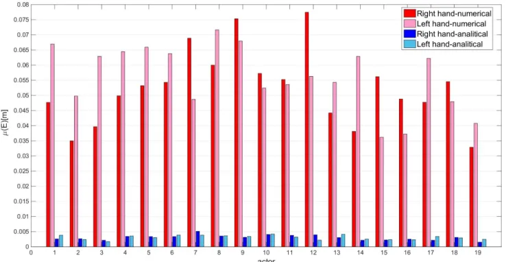
“cutting with knife” and “grating food”), each performed by 19 actors. The quality of imitation of one
motion was represented as
... ... ( ), ( ) ( a i N r i N ) hand hand P t P t d
Ε =µ , the mean value of the Euclidian distance
between the recorded positions of the hand joints
hand
a
P and those obtained with our imitation algorithm
hand
r
P for all samples of the motion. In order to present the general performance of the imitation algorithm
for each actor, we calculatedµ( )E and the mean value of E for all the motions performed by each actor. The general characteristics of our imitation algorithm for each actor expressed by µ( )E and the imitation algorithm proposed by Ude are shown in Fig. 8.
30
Figure 8. Quality of imitations of right and left hand motions of 19 actors, expressed by µ( )E , obtained by our (analytical) algorithm (blue) and the numerical algorithm proposed by Ude (red).
The results show that our imitation algorithm has average errors in following the desired hand positions of
about 3 mm for most actors. For some actors, these errors are somewhat bigger, about 5 mm. The reason is
a large disparity between the simplified human model represented by ROMEO and the kinematic model of
the real actor (confidence in the distance between joints).
5.2. ROMEO robot motion simulation and experimental results
The conversion process is based on the results obtained from the imitation algorithm, which are applied in
the algorithm for humanoid motion generation. The trajectories of the hand motions obtained for the
scaled robot model by using the imitation algorithm are shown in Fig. 9(b). Since the size of the robot was
not equivalent to the size of the actor, the desired hand trajectories during the motion without contact were
outside the robot’s workspace and the robot was unable to perform the motion. Therefore, the hand
31
characteristics, as proposed in our algorithm for humanoid motion. The generated trajectories of the
robot’s hands during the motion with and without contact, as well as the transition strategy, are shown in
Fig. 9(c).
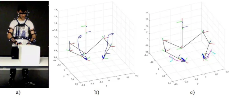
Figure 9. “Open/close drawer” task performed by the actor and the robot: (a) Actor during the task: simulation model of the robot and calculated trajectories of the robot’s hands, (b) in the imitation
algorithm, and c) in the algorithm for humanoid motion generation.
The trajectories depicted in cyan are the motions without contact with equipment, obtained as proposed in
Section 4.2; the trajectories in magenta represent the motions obtained with the transition strategy when
the contact between the hands and equipment was calculated according to the algorithm proposed in
Section 4.3; and dark blue represents the trajectories of the actor’s hands during motion with contact. The
desired trajectories of the robot’s hands are based on the results of the actor’s motion from the imitation
algorithm and/or the motion of the robot’s arms imitating human motion. Therefore, the robot’s hand
motion was free of both collision with equipment and self-collision, like the recorded human motion. The
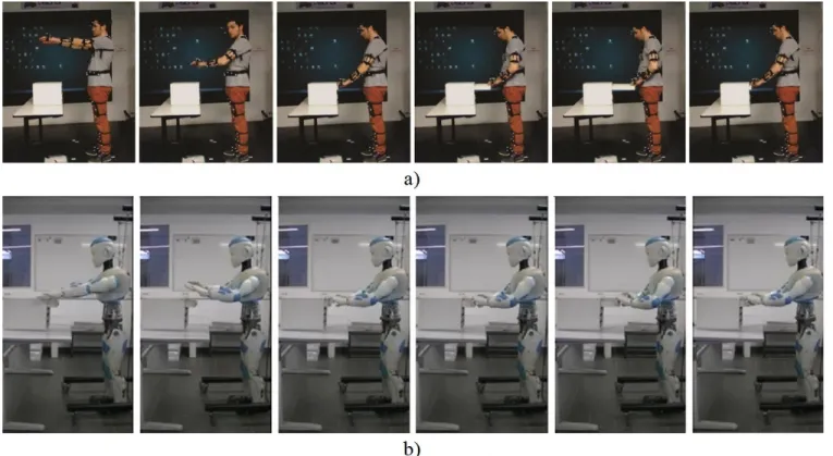
experimental results of the actor’s “open/close drawer” motion and the same motion performed by
ROMEO are shown in Fig. 10. The robot and the actor performed the task in the same environment. The
32
level of its chest, whereas the actor did so at waist level. ROMEO had conventional hands with flexible
fingers, which were not actuated and the robot was required to just open and close hands. This was the
reason why the drawer was ajar at the beginning of the experiment. With a robot that has complex hands
with actuated joints, the contact between the hands and the drawer would have been possible with the
drawer closed, exactly in the same manner as the actor performed the task.
Fig 10. Snapshot of the “open/close drawer” motion performed by: (a) the actor; (b) and the robot
ROMEO. The robot was able to perform the same task under the same conditions as the actor.
6. Conclusion
A conversion process for the imitation of dual-arm human motion, utilizing the upper body, has been
presented. It consists of an imitation algorithm and an algorithm for humanoid motion generation. The
imitation algorithm, defined for a scaled model of the robot ROMEO, is based on virtual markers which
33
is based on the analytical expression of Jacobian matrices and is able to define the expected motion of the
scaled robot in real time. Compared to existing algorithms, our imitation algorithm provides better
accuracy of motion imitation in Cartesian space. Precise imitation of hand motion in Cartesian space is
essential for a task where the hands come into contact with the environment. The algorithm for humanoid
motion generation is based on an inverse kinematic algorithm whose objective is to follow the desired
robot hand motions and, at same time, ensure that the motion of the humanoid resembles human motion
behavior. Since our task involved motion which included phases with and without contact between hands
and equipment, we additionally defined an algorithm for the transition between the phases. Therefore, by
way of an important contribution of this work, the proposed conversion algorithm is suitable for human
motion imitation by a humanoid for a task with and without contact, as well as complex tasks that involve
both types of motion, which other imitation algorithms are not. The results of our conversion process were
experimentally tested on the real robot ROMEO. Ultimately, one can say that the proposed conversion
methodology can be used as a universal and robust algorithm for human-to-humanoid motion conversion,
regardless of the type of dual-arm motion or the characteristics of the actor.
Acknowledgements
The research leading to these results has received funding from the Ministry of Education, Science and
Technological Development of the Republic of Serbia, under contract TR-35003, and the Equipex
Robotex project funded by CNRS under grant agreement No. ANR-10- EQPX-44-01.
References
1. M. Do, P. Azad, T. Asfour and R. Dillmann, “Imitation of human motion on a humanoid robot using
non-linear optimization,” In: Proceeding of the Humanoids 2008-8th IEEE-RAS International Conference
34
2. D. Vlasic et al, “Practical motion capture in everyday surroundings,” ACM transactions on graphics
(TOG) 26(3), 35 (2007).
3. N. Miller, O. C. Jenkins, M. Kallmann and M. J. Mataric, “Motion capture from inertial sensing for
untethered humanoid teleoperation,” In: Proceeding of the Humanoid Robots, 2004 4th IEEE/RAS
International Conference on IEEE (2004) 2 pp. 547-565.
4. S. Aloui, C. Villien, and S. Lesecq, “A new approach for motion capture using magnetic field: models,
algorithms and first results,” International Journal of Adaptive Control and Signal Processing 29(4),
407-426 (2015).
5. E. Ceseracciu, Z. Sawacha, and C. Cobelli, “Comparison of markerless and marker-based motion
capture technologies through simultaneous data collection during gait: proof of concept,” PloS one 9(3),
e87640 (2014).
6. H. Zhou, and H. Hu, “Human motion tracking for rehabilitation-A survey,” Biomedical Signal
Processing and Control 3(1), 1-18 (2008).
7. M. J. Gómez, C. Castejón, J. C. Garcia-Prada, G. Carbone and M. Ceccarelli, “Analysis and comparison
of motion capture systems for human walking,” Experimental Techniques 40(2), 875-883 (2016).
8. A. Billard et al, “Discovering optimal imitation strategies,” Robotics and autonomous systems 47(2),
69-77 (2004).
9. C. Ott, D. Lee, and Y. Nakamura, “Motion capture based human motion recognition and imitation by
direct marker control,” In: Proceedings of the IEEE-RAS International Conference on Humanoid Robots
(2008) pp. 399-405.
10. W. Suleiman et al, “On human motion imitation by humanoid robot,” In: Proceedings of the IEEE
International Conference on Robotics and Automation (ICRA 2008) (2008) pp. 2697-2704.
11. Q. Huang, Z. Yu, W. Zhang, W. Xu and X. Chen, “Design and similarity evaluation on humanoid
35
12. R.S. Jamisola, P.S. Kormushev, R.G. Roberts, et al., “Task-space modular dynamics for dual-arms
expressed through a relative Jacobian,” Journal of Intelligent & Robotic Systems 83(2), 205-218 (2016).
https://doi.org/10.1007/s10846-016-0361-0
13. A. Ude, C.G. Atkeson and M. Riley, “Programming full-body movements for humanoid robots by
observation,” Robot. Auton. Syst. 47(2), 93-108 (2004).
14. A. Ude, C. Man, M. Riley and C.G. Atkeson, “Automatic Generation of Kinematic Models for the
Conversion of Human Motion Capture Data into Humanoid Robot Motion,” In: Proceeding of the First
IEEE-RAS International Conference on Humanoid Robots (2000) pp. 2223 -2228.
15. K. Ayusawa, Y. Ikegami and Y. Nakamura, “Simultaneous global inverse kinematics and geometric
parameter identification of human skeletal model from motion capture data,” Mechanism and Machine
Theory 74, 274-284 (2014).
16. K. Ayusawa, M. Morisawa and E. Yoshida, “Motion retargeting for humanoid robots based on
identification to preserve and reproduce human motion features,” In: Proceeding of the Intelligent Robots
and Systems (IROS) (2015) pp. 2774-2779.
17. M. Tomić, C. Vassallo, C. Chevallereau, et al., “Arm Motions of a Humanoid Inspired by Human
Motion,” In New Trends in Medical and Service Robots. Springer International Publishing pp. 227- 238
(2016).
18. W. Khalil and J. Kleinfinger, “A new geometric notation for open and closed-loop robots,” Robotics
and Automation. Proceedings. 1986 IEEE International Conference on 3, 1174-1179 (1986).
19. ART GmbH, System user manual ARTtrack, TRACKPACK and DTrack, 2015, version 2.11.:
http://http://www.schneider-digital.com/support/download/Tools-Ressourcen/ARTTracking/Dokumentat
ion/ARTtrack DTrack TrackPACK User Manual 2.11.pdf/(last visited 2nd November 2016.)
20. FUI national Romeo project: http://projetromeo.com (last visited 2nd November 2016.)
36
3D Marker Data for Motion Recognition,” In: International Conference in Central Europe on Computer
Graphics, Visualization and Computer Vision (2008).
22. A. G. Kirk, J. F. O'Brien, and D. A. Forsyth, “Skeletal Parameter Estimation from Optical Motion
Capture Data,” In: Proceedings of the IEEE Computer Society Conference on Computer Vision and
Pattern Recognition (2005) 2 pp. 782-788.
23. B. Siciliano, L. Sciavicco, L. Villani, and G. Oriolo, “Robotics: modelling, planning and control,”
Springer Science and Business Media (2010).
24. K. Jovanović, V. Potkonjak, O. Holland, “Dynamic modeling of an anthropomimetic robot in contact
tasks,” Advanced Robotics 28(11), pp. 793-806 (2014).
25. M. Bagheri, “Kinematic analysis and design considerations for optimal base frame arrangement of
humanoid shoulders,” In: 2015 IEEE International Conference on Robotics and Automation (ICRA)
(2015) pp. 2710-2715.
26. P. Wenger, “Performance Analysis of Robots,” Modeling, Performance Analysis and Control of Robot
Manipulators 141-183 (2010).
27. C. W. Wampler, “Manipulator inverse kinematic solutions based on vector formulations and damped
least-squares methods,” IEEE Transactions on Systems, Man, and Cybernetics 16(1), 93-101 (1986).
28. P. Baerlocher and R. Boulic, “An inverse kinematics architecture enforcing an arbitrary number of
strict priority levels,” The visual computer 20(6), 402-417 (2004).
29. A. Safonova, N. Pollard, and J. K. Hodgins, “Optimizing human motion for the control of a humanoid
robot,” Proc. Applied Mathematics and Applications of Mathematics 78 (2003).
30. S. J. Orfanidis, “Introduction to Signal Processing,” Prentice-Hall (1996).
31. M. Mühlig, M. Gienger, and J. J. Steil, “Interactive imitation learning of object movement skills,”
Autonomous Robots 32(2), 97-114 (2012).


![Figure 6. Orientation and position errors between the recorded motion and the motion generated by our (analytical) imitation algorithm (blue scale) and the numerical imitation algorithm proposed by Ude [13]](https://thumb-eu.123doks.com/thumbv2/123doknet/12149124.311667/28.918.100.817.115.967/orientation-generated-analytical-imitation-algorithm-numerical-imitation-algorithm.webp)
![Fig. 7. Normed position errors in following real marker P rm with virtual marker P vm obtained with our (analytical) imitation algorithm (blue scale) and the numerical imitation algorithm proposed by Ude [13]](https://thumb-eu.123doks.com/thumbv2/123doknet/12149124.311667/29.918.90.834.629.997/position-following-analytical-imitation-algorithm-numerical-imitation-algorithm.webp)