HAL Id: hal-01619254
https://hal.archives-ouvertes.fr/hal-01619254
Submitted on 20 Oct 2018
HAL is a multi-disciplinary open access
archive for the deposit and dissemination of
sci-entific research documents, whether they are
pub-lished or not. The documents may come from
teaching and research institutions in France or
abroad, or from public or private research centers.
L’archive ouverte pluridisciplinaire HAL, est
destinée au dépôt et à la diffusion de documents
scientifiques de niveau recherche, publiés ou non,
émanant des établissements d’enseignement et de
recherche français ou étrangers, des laboratoires
publics ou privés.
A Review of Biogas Utilisation, Purification and
Upgrading Technologies
Olumide Wesley Awe, Yaqian Zhao, Ange Nzihou, Doan Pham Minh, Nathalie
Lyczko
To cite this version:
Olumide Wesley Awe, Yaqian Zhao, Ange Nzihou, Doan Pham Minh, Nathalie Lyczko. A Review of
Biogas Utilisation, Purification and Upgrading Technologies: Review. Waste and Biomass
Valoriza-tion, Springer, 2017, 8 (2), p.267-283. �10.1007/s12649-016-9826-4�. �hal-01619254�
A Review of Biogas Utilisation, Purification and Upgrading
Technologies
Olumide Wesley Awe1 · Yaqian Zhao1 · Ange Nzihou2 · Doan Pham Minh2 ·
Nathalie Lyczko2
of various technologies, recommendations are made on further research on the appropriate low cost technologies, especially using solid waste as low cost materials for biogas purification and upgrading.
Keywords Biogas upgrading · Biogas purification ·
Biogas utilization · Biomethane · CO2 removal · H2S removal
Introduction
Biogas is a renewable energy resource that can be an alter-native solution for the world insatiable energy demands and at the same time help in reducing waste and the greenhouse gases (GHG) emissions. It is also regarded as carbon neu-tral because the carbon in biogas comes from organic mat-ter (feedstocks) that captured this carbon from atmospheric CO2 over relative short timescale.
Biogas is produced from the methanation of biomass and organic wastes from sewage sludge anaerobic diges-tion, commercial composting, landfills, biomass gasifica-tion (thermos-chemical producgasifica-tion process), animal farm manure anaerobic co-digestion with energy crops, agro-food industry digestion facilities in both mesophilic (35 °C) and thermophilic (55 °C) conditions. These activities pro-duced biogas that is rich in methane (CH4), with higher heating value range from 15 to 30 MJ/Nm3 [1, 2]. Raw biogases from anaerobic degradation of sewage sludge, livestock manure, and agro-industrial bio-waste are gener-ally composed of methane (55–70%), and carbon dioxide (30–45%). Other gases (contaminants) present are nitro-gen (0–15%), oxynitro-gen (0–3%), water (1–5%), hydrocar-bons (0–200 mg m− 3), hydrogen sulfide (0–10,000 ppm
v), ammonia (0–100 ppmv), and siloxanes (0–41 mg Si m− 3)
Abstract Biogas is a valuable renewable energy and
also a secondary energy carrier produced from biodegrad-able organic materials via anaerobic digestion. It can be used as a fuel or as starting material for the production of chemicals, hydrogen and/or synthesis gas etc. The main constituents of biogas are methane (CH4) and carbon diox-ide (CO2), with various quantities of contaminants, such as ammonia (NH3), water vapour (H2O), hydrogen sulfide (H2S), methyl siloxanes, nitrogen (N2), oxygen (O2), halo-genated volatile organic compounds (VOCs), carbon mon-oxide (CO) and hydrocarbons. These contaminants pres-ence and quantities depend largely on the biogas source, which could be anaerobic digestion of many substrates and landfill decompositions. The removal of these contami-nants especially H2S and CO2 will significantly improve the quality of the biogas for its further uses. In parallel, biogas upgrading market is facing challenges in term of operating costs and energy consumption. The selection of appropriate technology depends on the specific biogas requirements, site specific, local circumstances and is case sensitive. This paper reviews the present state-of-the-art of biogas clean-ing and upgradclean-ing technologies, includclean-ing its composition, upgrading efficiency, methane recovery and loss. In addi-tion, biogas producaddi-tion, utilization and the corresponding requirements on gas quality for grid injection and vehicle usage are investigated. Based on the results of comparisons * Olumide Wesley Awe
wesley.awe@ucdconnect.ie
1 UCD Dooge Centre for Water Resources Research, School
of Civil Engineering, University College Dublin, Newstead, Belfield, Dublin 4, Ireland
2 Université de Toulouse, Mines Albi, CNRS UMR 5302,
Centre RAPSODEE, Campus Jarlard, Albi 81013 Cedex 09, France
[3, 4]. Biogas produced from landfills is some complex mixtures, which composed of methane (35–65%), carbon dioxide (15–40%), hydrogen (0–3%), carbon monoxide (0–3%), nitrogen (5–40%), oxygen (0–5%), water (1–5%), halogenated hydrocarbons (20–200 ppmv Cl−/F−), hydro-gen sulfide (0–100 ppmv), ammonia (0–5 ppmv), vola-tile organic compound (0–4500 mg/m3), and siloxanes (0–50 mg Si m− 3) [3, 5–7]. Typical compositions of differ-ent types of biogas which are comparable with natural gas and the possible impact of the contaminants are shown in Table 1.
Carbon dioxide (CO2) is a recalcitrant gas that reduces the density and decreases the calorific value of the biogas, but it is not toxic and corrosive like H2S. This last one is harmful to the environment and corrosive to the metallic parts of engines, pumps, compressors, gas storage tanks, valves and reduce the lifespan of process equipment [7, 8]. Contaminative components in biogas have to be removed before any eventual utilization. Basi-cally there are two steps involved in biogas treatment; cleaning (removal of harmful and toxic compounds such as H2S, N2, O2, Si, H, VOCs, CO, and NH3), and upgrad-ing (adjustment of CO2 content, to increase the calorific
value of the biogas to optimal level). Biomethane is the final product which composed of CH4 (95–99%) and CO2 (1–5%), with little or no trace of H2S [9]. Many biogas upgrading technologies has been developed in recent years, and their main differences are related to the nature of the operation. These include; physical, chemical, and biological, their efficiency and operational conditions, investment and maintenance costs. These technologies are still highly energy and chemical intensive, which has prompted the rapid development of biogas upgrading based on biotechnologies, because of their superior eco-nomic and environmental sustainability [10]. Therefore, as biogas upgrading market and technologies are rapidly evolving, there is need for frequent evaluation of these state-of-the-art technologies. This paper reviews the cur-rent available technologies for the removal of biogas con-taminants, with special focus on H2S, CO2, H2O, O2, N2, and siloxanes removal. The potentials and limitations of these technologies are also highlighted. In addition, new novel research by the authors on the valorization of cal-cium carbonate-based solid wastes, for removing the con-taminants from the biogas stream, was also discussed.
Table 1 Parameters and composition of gases from different origins, impurities and their consequences [1, 12, 33] Parameters Unit Biogas from AD Landfill gas North Sea
natural gas
Dutch natural gas Impact on biogas utilization
MJ/Nm3 23 16 40 31.6
Lower heating value KWh/Nm3 6.5 4.4 11 8.8
MJ/kg 20 12.3 47 38
Density Kg/Nm3 1.1 1.3 0.84 0.8
Relative density – 0.9 1.1 0.63 0.6
Wobbe index, upper MJ/Nm3 27 18 55 43.7
Methane number – >135 >130 73 –
Methane (CH4) Vol% 60–70 35–65 85–92 80–90
Heavy hydrocarbons Vol% 0 0 9 9
Water vapour (H2O) Vol% 1–5 1–5 – – Corrosion in compressors, gas storage tanks
and engines due to reaction with H2S,
NH3, CO2 to form acids
Hydrogen Vol% 0 0 0 –
Carbon dioxide Vol% 30–40 15–40 0.2–1.5 0.2–1.5 Decreasing calorific value, anti-knock prop-erties of engines and corrosion
Nitrogen, range Vol% 0–0.5 15 0.3–1.0 14 Decreasing calorific value, anti-knock prop-erties of engines and corrosion
Oxygen Vol% 0 1 – – Corrosion, fooling in cavern storage, risk of
explosion
Hydrogen sulphide Ppm 0–4000 0–100 1.1–5.9 – Corrosion, catalytic converter poison, emis-sion and health hazards. SO2, SO3 are
form
Ammonia (NH3) Ppm 100 5 0 – Emission, anti-knock properties of engines
and corrosion when dissolved Total chlorine as Cl− Mg/Mm3 0–5 20–200 – – Corrosion in engines
Recall of Biogas Production and Utilization
Due to its increased usage of biogas in many ways, such as production of heat and steam, electricity produc-tion and co-generaproduc-tion, vehicle fuel, feedstock for the production of bio-based chemicals and substrate in fuel cells, starting reactants in chemical processes, substitute for natural gas for domestic and industrial use, and gas grid injections [1], biogas production shows an increased trend in recent years. This is driven in Europe mainly by feed-in-tariffs, offered by different countries. This has led to the increase in biogas production plants in Europe from 17,240 with total installed electricity generating capacity of 8,339 MW at the end of 2014, a 18% increase compared to 2013. Germany leads the growth rate with 10,786 plants, followed by Italy with 1,491, UK 813, and France 733 [11]. The total amount of electricity produced from biogas is 63.3 TWh, enough for annual consump-tion of 14.6 million European. The major part of EU-27 renewable energy target (25%) by 2020 will be met by bioenergy [12]. According to Pike [13], the global power generation capacity will more than double in biogas pro-duction over the next decade, from 14.5 gigawatts (GW) in 2012 to 29.5 GW in 2022. Biogas can be deployed on both integrated and distributed basis, to meet demands in
heat, power, and transportation markets and at the same time address a range of environmental issues.
It should be noted that the final use of biogas is deter-mined by its composition, the upgrading process required, national framework such as tax systems, subsidies, avail-ability of heat and gas grids. Different countries have dif-ferent defined standard and specifications for utilization as vehicle fuel or for grid injection of upgraded biogas (Table 2). In Europe it is called gas grid injection and outside Europe, it is SoCalGas (Southern California Gas Company) “Rule 30”, which is stricter than European one and even Pacific Gas & Electric’s “Rule 21”. This is because of incremental specification for 17 “constituents of concerns” (CoCs) trace elements (it identified 17 for landfill gas, and 9 for digester gas) [14, 15]. The energy content (calorific value) of biogas is that 1 Nm3 (vol-ume) of biomethane contains 10 kWh primary energy, equivalent to 36 MJ, while natural gas energy content is 11.0 kWh. Considering 1 L of petrol equals to 9.06 kWh, implying that 1 Nm3 biogas corresponds to 1.1 L of pet-rol while 1 Nm3 of natural gas corresponds to about 1.2 L of petrol. This is the energy content of biogas in relation to other fuels. Other biogas utilization technologies and H2S requirements are shown in Table 3.
Table 2 Vehicle and grid injection specification standard requirement in some countries [4, 10, 14, 33]
a France allows flexibility in O
2 and CO2 under certain conditions
b Nertharlands also allowed <10–10.3 for regional grid c Chlorine compounds
d Flourine compounds e Ambient temperature
*Switzerland allowed unlimited gas injection
Compound Unit Germany Sweden France California Switzerland Netherlands Spain Wobbe index(H) MJ/Nm3 46.1–56.5 44.7–46.4 48.2–56.5 47.6–51.6 47.9–56.5 43.46–44.41 48.3–57.8
Lower (L) 37.8–46.8 43.9–47.3 42.5–46.8 *Unlimited
Methane content Vol% – ≥97 ≥86 – ≥96 ≥85 ≥95
Carbon dioxide Vol% ≤6 (dry) ≤3 ≥2.5a 3 ≤4 ≤6b 2.5
Hydrogen Vol% ≤5 ≤0.5 ≤6 – ≤4 <12 – Oxygen Vol% ≤3 ≤1 ≤0.01 <0.2 ≤0.5 ≤0.5 0.01 CO2 + O2 + N2 – – ≤5 – – – – <4 H2S Ppm <5 <15.2 ≤5 88 ≤5 ≤5 15 Total sulfur Ppm <30 <23 <30 265 <30 <45 50 Mercaptans Ppm ≤15 – ≤6 106 ≤5 ≤10 17 Ammonia (NH3) Ppm ≤20 ≤20 ≤3 ≤0.001 mol% ≤20 ≤3 ≤3
Siloxanes (Si) mg m− 3 0.1 or free ≤5 ppm
6.2 (Si) ≤10 Halogenated compounds mg m− 3 ≤1 ≤1 ≤1c
<10d ≤0.1 ppm ≤1 ≤50
c
≤25d ≤1
Water dew point °C Ground Temp ≤ −5e
Biogas Upgrading Technologies
Biogas purification and upgrading had been researched extensively in recent years. Hosseini and Wahid [2] reviewed biogas purification processes with the focus on contaminants removal, while Ryckebosch et al. [7] reported on various techniques for biogas transformation regarding their conditions, functioning, bottlenecks and efficiency. Bauer et al. [16] reviewed the commercial technologies on biogas upgrading. Most recently, Munoz et al. [10] pro-vided a state of the art review on the biogas upgrading tech-nologies with emphasis on biotechtech-nologies for CO2, H2S, Siloxanes and halocarbon removal. Sun et al. [12] worked on appropriate biogas upgrading technology, focusing on product purity and impurities, methane recovery and loss, upgrading efficiency, investment and operating cost.
From the literature, the main techniques for biogas upgrading and purification are: water scrubbing, adsorption (physical and chemical), cryogenic separation, membrane technology, biological upgrading and in-situ upgrading methods.
CO2 Removal from Gas Stream
Removal of CO2 is necessary in order to increase the den-sity and calorific value of the gas to meet Wobbe Index quality and specifications (Table 2). The current technolo-gies are: pressure swing adsorption, physical absorption (water and organic solvent scrubbing), chemical absorp-tion, cryogenic separaabsorp-tion, membrane separaabsorp-tion, biologi-cal methane enrichment. These are discussed in the order of old, current trends, and future technologies and ideas.
3.1.1 Physical Absorption (Water Scrubbing and Organic Solvent Scrubbing)
The separation principle of absorption is based on dif-ferent solubility of various gas components in a liquid scrubbing solution. The absorbed gas components are physically bound to the scrubbing liquid. In this case water is a selective absorbent and it is widely used in water scrubbing of biogas at an industrial scale, with 41% share of the global biogas upgrading market because of its less sensitivity to biogas impurities [17]. The solubil-ity of CH4 is 26 times lower at 25 °C than that of CO2 [18]. Also according to Persson et al. [3], the different biding forces of the more polar CO2 or H2S and the non-polar methane are used to separate these compounds.
Therefore, H2S can be removed together with CO2 in principle because the solubility of H2S in water is higher than that of CO2. It is however advisable to separate the H2S prior to CO2 removal because the dissolved H2S is very corrosive and odour nuisance can cause opera-tional problem. Biogas scrubbing is carried out in a col-umn packed with Pall or Raschig to support an efficient gas–liquid mass transfer, in a countercurrent (compressed gas at 6–10 bar the bottom and water pressures from the top) [7, 16]. The used water is regenerated in desorp-tion column with, either air or steam that release the CO2 from the water at a decreased pressure (Fig. 1). It should be noted that N2 and O2 cannot be separated because they are non-condensable. Energy consumption is for gas compression, recirculation pumps and water regenera-tion. Constant purging of water is necessary to avoid H2S poisoning and fouling.
An organic solvent such as methanol and dimethyl ethers of polyethylene glycol (DMPEG) can be employed in CO2 removal. The solvent can simultaneously absorb CO2, H2S and H2O since they have higher solubility in polyethylene glycol than CH4. The scrubbing and regeneration process is the same as water solvent (Fig. 1). The trade names for the solvents are Selexol® and Genosorb® and they exhibit higher affinity for CO2 and H2S than water by five times, especially Selexol®, which is a mixture of dimethyl ethers of polyethylene glycol [19]. As a result, smaller absor-bent volume is needed with compact size and little pump-ing with the same quantity of biogas, thereby reducpump-ing the investment and operating cost. According to Bauer et al. and Sun et al. [12, 16], a consistent biomethane con-tent of 96–98.5% and less than 2% methane losses, can be achieved in an optimized full-scale plant, with the similar energy consumption as water scrubbing [7, 8, 17]. This process can produce high purity CO2, and additional dry-ing of the upgraded gas is not necessary due to the fact that water and halogenated hydrocarbon (from landfill) are absorbed by glycol [3].
Table 3 Biogas utilization technologies and H2S requirements [3, 16,
33]
Technology H2S tolerance (ppm) Heating (boilers) and stirling
engines <1000
Kitchen stoves <10
Internal combustion engines <500 ppm (depending on the kind of engine; it can be <50 ppm)
Turbines <10,000
Micro-turbines <70,000 Fuel cells
Proton exchange membrane
(PEM) <1
Phosphoric acid fuel cell
(PAFC) <20
Molten carbonate fuel cell
(MCFC) <10 in fuel (<0.1–0.5 at the anode) Solid oxide fuel cell (SOFC) <1
3.1.2. Chemical Absorption
This is the same way as water/glycol scrubbing for biogas–liquid mass transfer principles, but chemical reac-tion takes place between the solvent and the absorbed sub-stances. It relies on CO2 reactive absorbents such as alkanol amines (mono ethanol amine (MEA)) or di-methyl ethanol amine (DMEA), and alkali aqueous solutions such as KOH, K2CO3, NaOH, Fe(OH)3, FeCl2 [20]. The unit consists of a packed bed (random or structural) coupled with desorption unit equipped with reboiler to simplify process configura-tion, with no risk of biomass growth as result of high pH of the amine solutions [4]. Amine solution is widely used to absorbed CO2 and there is little or no methane losses (0.1–1.2%), with methane recovery greater than 99% because the chemical solvent reacted selectively with CO2. Although some reports [7, 8, 16, 20] reported methane losses up to 4% due to CH4 dissolution in alkanolamine. It also operated like water scrubbing countercurrent flow configuration, and H2S should be treated prior to chemical scrubbing because of amine poisoning (Fig. 2). The regen-eration is usually accomplished with steam or heat and CO2 with purity of 93% reportedly recovered in the process [21]. Despite its high CO2 removal efficiency, energy con-sumption is relatively high (high regeneration heat), there is likely possibility of salt precipitation and foaming to occur coupled with O2 poisoning of amine and other chemicals [4, 21].
3.1.3 Pressure Swing Adsorption (PSA)
The process take place in vertical columns packed with absorbents under adsorption, depressurization, desorp-tion and pressurizadesorp-tion sequences, and the molecular sieves material is regenerated (Fig. 3). In the pressurized column methane-rich gas passed through while CO2 is adsorbed. The most commonly used adsorbents are zeo-lite, activated carbon, activated charcoal, silica gel and synthetic resins. This can be used to separate CO2, N2, O2 and H2S from the gas streams by selectively adsorption of CO2 over CH4 onto the porous adsorbents with a high specific area, since CH4 molecule is larger than the other gas molecules [4]. It is also advisable to dry (cool) the gas and also remove H2S prior to CO2 adsorption because H2S will adsorbed irreversibly to the molecular sieves [6].
After saturation with CO2, biogas is led to a new col-umn, while CO2 saturated column is stepwise depressur-ized (almost atmospheric pressure), to release CO2/CH4 mixture with high methane content, which is vacuum and recycle back to the PSA inlet. According to Bauer et al. [4], several columns were linked together to create a continu-ous operation and to reduce energy need for gas compres-sion. The CH4 recovery rate of 96–98%, with 2–4% meth-ane losses had been reported [7, 16]. The off-gas must be treated (burnt in a flox burner) to avoid release methane to the atmosphere, or use for combustion.
3.1.4 Cryogenic Separation of CO2
This new technology uses temperature difference to sepa-rate the gases. CO2 has a boiling point of −78 °C, while methane is −160 °C, resulting in CO2 separation from the biogas by cooling the gas mixtures at elevated pressure (Fig. 4). This difference in condensation temperatures can be exploited to separate other gases like N2, O2 and silox-anes from the biogas through condensation and distilla-tion. According to Hosseini and Wahid [2], the process
is of specific value when the final product is liquid biom-ethane (LBM), which is equivalent to liquid natural gas (LNG). The process is more advantages for treating land-fill gas, for pure CO2 production (98%), high-purity meth-ane with less than 1% losses and can be utilized directly for vehicles or injected to grid as gas. The energy con-sumption is however high with raw biogas compressed at 200 bar, which can amount to 5–10% of the biomethane produced [6, 12, 15].
Fig. 2 Biogas upgrading by chemical absorption (Amine scrubbing) of CO2
3.1.5. Membrane Separation
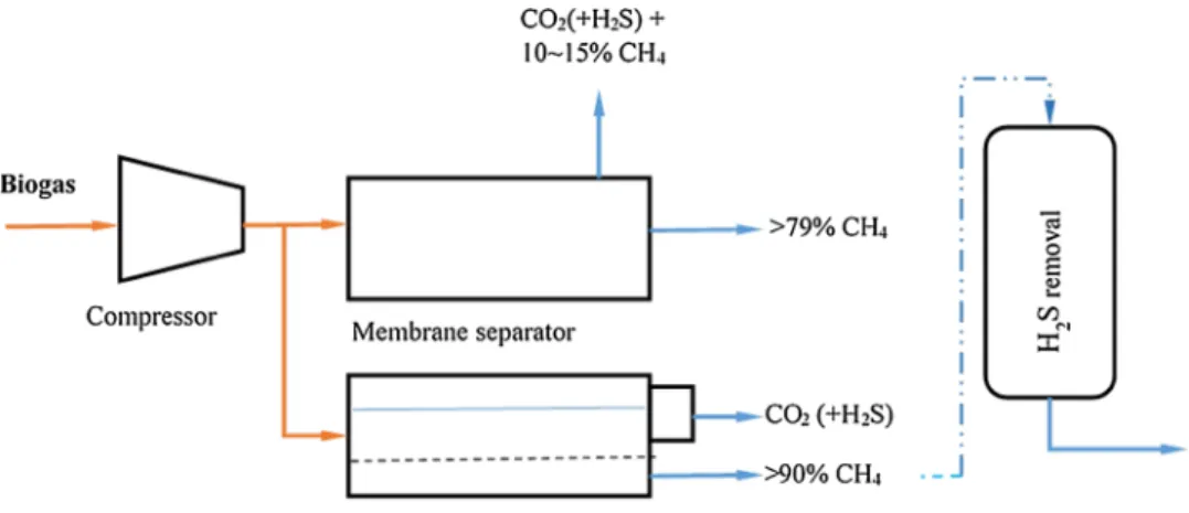
The separation is based on the selective permeability prop-erty of the membranes, which can be gas–gas separation (gas phase on both side of the membranes) or gas–liquid separation (liquid absorbs the H2S and CO2 molecules dif-fusing through the membranes). The liquid solution can be amine and the system is highly selectively compared to the solid membrane systems, and operated well at low pres-sure [3]. The material used is micro porous hydrophobic membrane, which separates the gaseous molecules stream flowing in one direction with the liquid flowing in counter-current flow from the other side and diffused through the membrane. The amine solution can be regenerated with heating to release the CO2, which can be collected sepa-rately (Fig. 5).
On the other hands, the gas–gas separation works at high pressure greater than 20–40 bar or at lower pressure of 8–10 bar, resulting in 92–97% methane production [16]. This technology allows CO2, H2S, H2O, O2 pass through the membrane to the permeate side while retaining CH4 on the inlet side. Some methane losses are possible since the CH4 may also pass through the membrane in an effort to achieve higher purity [3, 12]. Higher purity of CH4 can be achieved with larger size or several membranes in series. Therefore, there is need to balance the desire for high purity methane and low methane loss. Recirculation of off-gases
can help in reducing this loss. Membrane is based on dif-ferent molecules of different sizes with different permeabil-ity through the membrane, and is also driven by pressure difference between the two sides of the membrane and the biogas temperature [7]. Deng and Hagg [21] worked on the efficiency of CO2-selective polyvinylamine/polyvinylacho-hol blend membrane and reported that the optimal process can deliver 98% CH4 purity. Scholz et al. [22] reviewed membrane based technologies used for commercial biogas upgrading. He reported that single stage permeation pro-cess are not able to produce high CH4 purity and simul-taneously obtain a high CH4 recovery. He concluded that, multistage concepts are mandatory.
3.1.6 Hydrate Formation
The process was firstly proposed by Yoon and Lee [23] who investigated clathrate phase equilibrium for the water-phenol-carbon dioxide system based on the equilib-rium partition of the components between gaseous phase and the hydrate phase. Kang et al. [24] used this princi-ple to work on gas hydrate process of recovery of CO2 from fuel gas. According to Tajima et al. [25], the basic mechanism of the separation process is a selective parti-tion of the target component between the hydrate phase and the gaseous phase. Generally, the hydrate phase is stable under high pressure-low temperature conditions.
Fig. 4 Flowsheet of cryogenic
separation of biogas (removal of CO2)
Fig. 5 Membrane biogas
puri-fication process combined with H2S removal (hybrid system)
This has attracted other researchers to look at the possi-bility of employing this technology to reduce CO2, H2S, and other contaminants from biogas and syngas streams. For example, Wang et al. [26], investigated the recov-ery of hydrogen from refinrecov-ery (hydrogen + methane) gas mixtures using hydrate technology, while Yang et al. [27] worked on progress and perspectives in converting biogas to transportation fuels. The process has also been suc-cessfully utilized to remove CO2 from contaminated natu-ral gas. According to [3], there was 16% reduction in the CO2 content from CH4/CO2 ratio of 75/25%, but meth-ane loss was still relatively high. It was also reported that the CO2 capture by hydrate formation consumes a large amount of energy, as a result of high pressure required for hydrate formation [12, 25–27]. This technology can be improved upon to reduce energy consumption, meth-ane loss and simplify the separation process for adaptable for future use.
3.1.7 Biological Methane Enrichment (Biotechnological)
Strevett et al. [28] reported the microbial conversion of CO2 and H2 to CH4 based on the ability of hydrogenotropic methanogens capacity to use CO2 as their carbon source and electron acceptor, and H2 as electron donor in the energy yielding reaction.
Other studies of CO2 conversion using H2 as electron donor were also reported in recent years. Kim et al. (2013) used CO2 off-gases from electronic production waste to produce methane under mesophilic and thermophilic con-ditions. Luo et al. [30] worked on simultaneous H2 utilisa-tion in in-situ biogas upgrading with CH4 content of 95% under various conditions, while Bauer et al. [4] investigated process performance and microbial activities during co-digestion of manure with whey. Several microorganisms’ species from Archaeal family such as Methanobacterium sp., Methanothermobacter sp., Methanococcus ap.,
Metha-nosarcina sp., Methanosaeta sp., Methanoculleus sp. and Methanospirillums sp. were reported in stand-alone
biore-actors and anaerobic digesters upgrading CO2 to CH4 by H2 injection [10, 29, 30].
It is equally possible to upgrade syngas to methane since biomass gasification process contained CO, CO2, H2, based on the ability of methanogens to convert CO to CH4 and CO2, with the following reaction [10]:
Also, Yan and Zheng [31] employed microalga photo-synthesis to sequester anthropogenic CO2 and reported that CH4 content of the upgraded gas could reach 90–95%.
(1) 4H2+CO2 → CH4+2H2O (ΔGo= −131KJ)
(2) 4CO + 2H2O → CH4+3CO2
3.1.8 Perspectives on CO2 Removal
Table 4 summaries the advantages and disadvantages of the technical alternatives and features of CO2 removal from biogas streams. The chemical and physical absorp-tion technologies are feasible and had been used widely in practice. Water as absorbent is cheap, efficient and environmentally friendly, but required intensive energy for pressurization and regeneration. More effective absorbents are very expensive and usually have nega-tive environmental impacts. Yet, these technologies can be improved, especially their efficiency and reduction in their energy demand by looking at possibility of upgrad-ing biogas at low temperature and pressure to save cost. Ideally, biogas produced exit digesters at minimum 35 °C, heat exchanger can be used to increase or decrease the heat need for various upgrading systems. For example, the saved heat can be used for water regenerations in water scrubbing, PSA, steam generation during the strip-ping of CO2 for water and solvent recirculation.
Innovative approach to solvent based CO2 absorption is required, and this must be economically viable with minimum environmental impacts. This will also depend on the selection of appropriate absorbents, the separation process, the intensity of the energy requirement, effective integration of biogas purification, and the upgrading pro-cess to save cost.
Cryogenic is a promising upgrading technology for CO2 removal, especially with capability to produce liquid CO2, which can be utilized in technologies that requires pure CO2. It can also produce liquid biomethane (LBM) which is equivalent of liquid natural gas (LNG) for trans-portation fuel [1]. The energy consumption is very high for separating the gases into various components, but with recent interest in LBM production, the solution to the existing problem can be overcoming through research and development.
Hybrid systems involving the integration of two or more purifications and upgrading methods in order to exploit their advantages and also bridge their drawbacks is another possible option for CH4/CO2 separation. The integration of different technologies into one unit will lead to reduction in CH4 losses, minimising capital cost and recurrent cost, reduce footprint of the conditioning systems. Innovative solution can overcome other impu-rities such as H2S degradation or contamination of the absorbent, and thereby allow the absorbent to be eas-ily and cheaply regenerated with minimum of gases concentration.
It is worthwhile noting that the valorization or the stor-age of CO2 recovered is also an option in biogas upgrad-ing. However, it is out of the scope of the review.
Table 4 Alter nativ es and tec hnical f eatur es of CO 2 remo val fr om g as s treams [ 3 – 5 , 7 , 8 , 10 , 30 ] Tec hnology/alter nativ es Adv ant ag es Disadv ant ag es Absor ption (w ater scr ubbing) High e ffi ciency (>97% CH 4 ) Simult aneous r emo val of H2 S (when H2 S <300 cm 3/m 3) Capacity is adjus table b y c hanging tem per atur e or pr essur e Lo w CH4 losses (<2%), t oler ant t o im pur ities, R eg ener ation pos-sible Expensiv e in ves
tment and oper
ation Cos t: 0.105 € m − 3 (250 Nm 3/h) and 0.052 € m − 3 (2000 Nm 3/h) Po wer cos t: 0.4–0.5 kWh m − 3 pr oduce g as Clogging due t o bacter ial g ro wt h Possible f oaming, lo w fle xibility t ow ar d v ar iation of in put g as Absor ption (or ganic sol vent–pol ye th ylene g ly col) High e ffi ciency (>97% CH 4 ) Simult aneous r emo val of or ganic com ponents, H2 S, NH 3 , HCN and H2 O Ener ge tic mor e f av or able t han w ater Lo w CH4 losses, r eg ener
ation possible wit
h lo w-tem per atur e w as te heat Expensiv e in ves
tment and oper
ation Po wer cos t: 0.21 kWh m − 3 of g as Di ffi cult oper ation Incom ple te oper ation when s tripping/v acuum (boiling r eq uir ed), reduced oper
ation when dilution of g
ly col wit h w ater Chemical absor ption (Amines) High e ffi ciency (>99% CH 4 ) Cheap oper ation, r eg ener ativ e, mor e C O2 dissol
ved per unit of
volume com par ed wit h w ater , v er y lo w CH4 losses (<0.1%) Po wer cos t: 0.05–0.25 kWh m − 3 of g as Expensiv e in ves tment, heat r eq uir ed f or r eg ener ation, cor rosion, decom
position and poisoning of t
he amines b y O2 or o ther c hemi-cals, pr ecipit ation of salts, f oaming possible PS A/V SA
(Carbon Molecular sie
ves, Zeolites Molecular sie
ves Alumina silicates) Highl y e ffi cient (95–98% CH 4 ), H2 S is r emo ved, lo w ener gy used: high pr essur e but r eg ener ativ e, com pact tec hniq ue, also f or small capacities, t oler ant t o im pur ities Expensiv e in ves
tment and oper
ation, e xtensiv e pr ocess contr ol needed, CH 4
losses when malfunctioning of v
alv es Membr ane tec hnology (Gas/g as or g as/liq uid) H2 S and H2 O ar e r emo ved, sim ple cons truction, sim ple oper ation, high r eliability , small g as flo ws tr eated wit hout pr opor tional incr ease of cos ts Gas/g as r emo val e ffi ciency <92% CH 4 (1 s tep) or >96% CH 4 , H2 O is r emo ved Gas/liq uid r emo val e ffi ciency >96% CH 4 , c heap in ves
tment and oper
ation, Pur e C O2 can be pr oduced Lo w membr ane selectivity : com pr omise be tw een pur ity of CH 4
and amount of upg
raded biog as, multiple s teps r eq uir ed (modular sy stem) t o r eac h high pur ity , CH 4 losses Cos t: 50 Nm 3 /h (0.432 ct Nm − 3 ); 200 Nm 3 /h (0.211 ct Nm − 3 ) Po wer cos t: 0.22 kWh m − 3 pr oduce g as CH4 losses <10% Cr yog enic separ ation 90–98% CH 4 can be r eac hed, CO 2 and CH 4 in high pur ity , lo w extr a ener gy cos t t o r eac h liq uid biome thane (LBM) Expensiv e in ves
tment and oper
ation CO2 can r emain in t he CH 4 , High ener gy r eq uir ed f or cooling Biological r emo val Air/o xy
gen dosing dig
es ter slur ry Biofilter/Bio tric kling filter (Biog asCleaner ®, Biopur ic ®, DMT filter ®) Bioscr ubber (Thiopaq™) Remo val of H2 S and CO 2 Enr ichment of CH 4 No un wanted end pr oducts DMT filter
® can handle air flo
w r ates of be tw een 10 m 3/h and 100,000 m 3/h wit hout an y pr oblem Addition of H2, s till on e xper iment al basis (no t on lar ge-scale)
H2S Removal from Biogas Stream
Hydrogen sulfide along with other S bearing compounds (mercaptans etc.) are the most common contaminants in biogas and their quantity, which can vary from 100 to 10,000 ppm, depends largely on the composition of the organic matter (but, mostly protein-rich). They must be removed before any utilization because they are highly cor-rosive to pipes, pumps and engines and they have environ-mental concerns due to their conversion to sulfur dioxide (SO2) and sulfuric acid (H2SO4) [2]. Ammonia, like H2S, is highly corrosive when combusted and can transformed into nitrogen oxides (NOx), which are part of greenhouse gases that are causing climate change and polluting the environ-ment. As such, H2S and NH3 need to be removed early in the upgrading process, preferably in the digestion chambers or in the gas stream of the upgrading process.
3.2.1 Physical and Chemical Absorption
The upgrading process takes place in conventional gas–liq-uid contactors (packed bed or spray towers) using either water or organic solvent in the physical absorption process or using aqueous chemical solutions to convert H2S to ele-mental sulfur or metal sulfide [32]. Single pass absorption and regenerative absorption are commonly used, but high water consumption is needed without the regeneration step. Therefore, Selexol (mixture of dimethyl ethers of polyeth-ylene glycol), which exhibits higher affinity for H2S than water by five times can be used, resulting in smaller absor-bent volume with compact size and require regeneration step [7]. This is suitable for the removal of low concentra-tion of H2S or in combination with CO2 removal (Fig. 6).
To achieve an efficient H2S mass transfer, the addi-tion of chemical reagents, such as NaOH, FeCl2, Fe3+/MgO, Fe(OH)
3, Fe3+/CuSO4 and Fe3+/EDTA
(ethylenediaminetetraacetate), will reduce liquid to gas ratio because of the quick chemical reactions with these solvent [7, 12]. Petersson and Wellinger [33] reported the reaction of H2S with NaOH and produced soluble salt of sodium sulfide (Na2S) and sodium hydrogen sulfide (NaHS), where the precipitate is not regenerated with consequence of disposal problem. The dilution of iron salt (FeCl2) solvent with H2S is based on the formation of insoluble FeS that also needs to removed and disposed, while Fe(OH)3 addition can remove H2S, resulting in for-mation of Fe2S3 and regeneration is possible with oxygen or air [32].
Regarding the chemical absorption of H2S, an iron-chelated Fe3+/EDTA solution (0.2 mol) is the most popular catalyst to be used, resulting in production of elemental sulfur (S) during the reduction of Fe3+ to Fe2+ according to the following reaction:
The regeneration of iron-chelated Fe3+/EDTA solution occurs by its oxygenation according to Eq. 4, followed by conversion of pseudo-catalyst into its active form Fe3+ in Eq. 5:
Large consumption of chemical is avoided due to the regeneration Fe3+/EDTA solution and it is H
2S spe-cific, with H2S removal rate of 90–100% at a gas flow rate of 1 dm3/min with catalytic solution flowing rate of 83.6 cm3/min [7]. The iron-chelated based technologies were also reported to remove 50–90% of the mercap-tans presented in the biomethane, without any significant reduction in the concentration of CO2 with operation cost of 0.2–0.3 €kgS− 1 [2]. The available materials for (3) S2−+2F3+ → S + 2Fe2+
(4) 0.5O2(g) + H2O(l) → 0.5O2(aq)
(5) 0.5O2(aq) + 2Fe2+ ↔ 2Fe3++2OH−
Fig. 6 Biogas upgrading by
chelated and non-chelated are Lo-Cat®, SulFerox®, and Sulfothane® Bailon et al. [6].
3.2.2. Dosing with Air/Oxygen into Biogas System (In-situ)
Microorganisms can be employed for desulphurization of biogas. This technique is based on the conversion of H2S to elemental sulfur by a group of specialized microorganisms through microbiological oxidation process. The microor-ganisms employed are Thiobacillus family and they use the CO2 from the digester as their carbon source. Depending on the H2S concentration, small amount of oxygen (2–6% of air in biogas) is needed for the biological reaction to take place (Eq. 6), by injecting air directly into the digester.
H2S concentration can be reduced by 95% to less than 50 ppm, depending on the temperature, the reaction time, and the amount of air added. However, safety measures must be taken to avoid overdosing of air, as biogas air in the range of 6–12% is highly explosive [3, 33]. However, it is worthwhile noting that this approach is not suitable for upgrading biogas to natural gas quality since excessive oxy-gen and inert gas use have to be remove from the treated gas [5].
3.2.3. Iron Chloride (FeCl2) Dosing into the Digester
(In-situ H2S Precipitation)
H2S can be reduced by adding Fe2+ or Fe3+ in the form of FeCl2, FeCl3 and FeSO42 into the digester or the influent mixing tank. According to Persson et al. [3], FeCl2 is the most regularly used as the Fe2+ reacts with S2−, leading to insoluble iron sulfide (FeS) formation (Eq. 7).
The resultant FeS can be removed from the system with discharged solids. When it is spread as fertilizer, it is oxi-dized by atmospheric oxygen, forming soluble salt which acts as nutrients to the plants. Although this method is effective in reducing H2S, but less effective to reduce it up to the level of vehicle and injection into the gas grid speci-fications. H2S reduction to 100–200 ppm has been reported, depending on the amount of iron chloride added [5].
3.2.4. Adsorption Using Iron Oxides/Hydroxides Fe2O3/ (Fe(OH)3)
This is a process based on two parallel adsorbent columns packed with either activated carbon, iron oxide (Fe2O3), iron hydroxide (Fe(OH)3) or zinc oxide (ZnO), config-ured in adsorption and regeneration mode. The principle is that H2S reacts easily with Fe2O3, Fe(OH)3 or zinc oxide (6) 2H2S + O2 → 2S + 2H2O
(7) Fe2++S2− → FeS
to form insoluble FeS or ZnS, respectively. The materials used to immobilize the chemical reagents are steel wool (cover with rust), wood chips covered with iron oxide, or pellets made of red mud (aluminum manufacture waste) [2]. However, wood chips impregnated with iron oxide are mostly used, because it has a larger surface to volume ratio than plain steel and inexpensive [16].
It was reported that at H2S concentration of 1,000–4,000 (ppm), 100 g of pellets can bind 50 g of sulfide. The con-ventional available materials (iron sponge) grades are; 100, 140, 190, 240 and 320 kg Fe2O3, with density of 800 kg/ m3. However, recently, a numbers of proprietary iron oxide materials have been offered as improved alternatives to the conventional ones, such as Sulphur-Rite®, SulfaTreat®, SOXSIA®, Meda-G2®, and Sulfa-Bind® [5, 33].
3.2.5. Adsorption on Activated Carbon
H2S can be removed using adsorption into non-impregnated (virgin), catalytic-impregnated, and impregnated activated carbons. The catalytic-impregnated and impregnated acti-vated carbons will catalyze H2S oxidation to elemental sul-fur and water at higher rate than the virgin activated carbon (AC) [2]. As in biological desulphurization, oxygen (4–6%) can be added (catalytically) to convert H2S to elemental sulfur and water (Eq. 8) [7]:
The required pressure for this reaction to occur is between 7 and 8 bar and temperature 50–70 °C. The formed elemental sulfur is adsorbed by the AC (Fig. 7). In other to improve the rate of reaction, chemical adsorption is done by impregnating the AC with alkaline or oxide such as sodium carbonate (Na2CO3), potassium iodine (KI), sodium hydroxide (NaOH), potassium hydroxide (KOH), sodium bicarbonate (NaHCO3), and potassium permanga-nate (KMnO4). This can enhance the removal capacity from a normal 10–20 kg H2S/m3 (virgin carbon) to 120–140 kg H2S/m3 (impregnated carbon) [6]. According to Petersson and Welinger [33] only KI or KMnO4 impregnation sup-ports the partial oxidation of H2S without any added oxy-gen. As a result, they are more preferred option for any desulphurization that will lead to biomethane injection to national grid or for vehicle fuel utilization. Two connected columns were used for continuous operation for adsorption and desorption, with heat (steam injection) and depressuri-zation usually employed for regeneration. The drawback of this technology is the replacement of the activated carbon instead of regeneration when the solid is saturated with sulfur, and there is a growing environmental concerns over appropriate disposal methods. In addition, dust and water must be removed prior to AC treatment [10, 34].
(8) 2H2S + O2 → 2S + 2H2O
3.2.6. Biological Desulphurization and Biofiltration of H2S
This technology employed specialized microorganisms to reduce the level of H2S in biogas by converting it to ele-mental sulfur and some sulphates, similar to the technique of addition of air or oxygen into the digestion tank. The technique is on the basis of lithautotrophic bacteria to use H2S as electron donor and CO2 as carbon source, and also for the development of end-of-pipe solutions for biogas upgrading (Montebello [36]; Mora et al. [37]). About 4–6% of air/oxygen was used as electron acceptor and provided the energy needed for lithotrophic growth in order to oxi-dize H2S (Eqs. 9 & 10) [36].
Bailon and Hinge [5] had proved that it is possible to use NO3− (NO2−) as electron acceptor instead of using O2 in the biofiltration unit for the oxidation of H2S (Eqs. 11,
12) due to the fact that at the low O2/S and NO3−/S ratio, elemental sulfur is produced.
The sulfur oxidizing microorganisms used are mainly from the family of Thiobacillus, Thiomonas, Paracoccus, Acidithiobacillus, Sulfurimonas or Halothiobacillus [35]. The optimum temperature is in the range of 28–35 °C, with pH of 6–8. However, Montebello [35] discovered that some extremophile species such as Acidithiobacillus ferrooxidants or Acidithiobacillus thioxidants, present an optimum biocatalytic activity in the low pH range of 2–4. This technology has been implemented mainly in biotrick-ling filter (BTF), due to its efficient gas–liquid mass trans-fer, cost effectiveness, and easy control of other variables
(9) H2S + 0.5O2 → S + H2O (10) H2S + 2O2 → SO2−4 +2H+ (11) 3H2S + NO−3 ← 3S + 0.5N2+3H2O (12) 3H2S + 4NO−3 → 3SO2−4 +2N2+6H +
like nutrients supply, pH and temperature [10, 35, 36]. H2S can be reduced from 3000–5000 ppm to 50–100 ppm, and ammonia (NH3) is also jointly removed [3]. The packed bed columns materials for supporting biofilm growth in BTF desulphurization are pall rings, HD-QPAC or polyu-rethane foam etc.
3.2.7. Membrane Separation
This is similar with CO2 removal process by membrane separation. The separation is based on the selective perme-ability property of the membranes, which can be gas–gas separation or gas–liquid separation. This allows the perme-ability of H2S while retaining the CH4 on the other side of the membranes. In the gas–liquid separation, alkaline liquid is used on the microporous hydrophobic membrane, which can support H2S removal by 98% during desulphurization, leaving only 2% in the upgraded gas [7, 21, 22]. The gas stream molecules flow in one direction diffusing through the membrane, while H2S is absorbed by the liquid on the other side. Iovane et al. (2014) recently worked on experi-mental test with polymeric membrane (150 × 1210 mm) for the biogas purification from CO2 and H2S and reported the H2S removal efficiency of 54–94% at pressures of 25–41 (N/cm2).
3.2.8 Perspectives on H2S Removal
Table 5 shows the summary of the alternatives and techni-cal features of H2S and other contaminants removal from gas streams. It should be note that H2S is poisonous and corrosive in nature, which make regeneration almost impos-sible, and very expensive to manage, where possible. The possible solution is to focus on research and development that can produce a system for sulfur recovery at less cost, while minimizing its impact on equipment and the environ-ment. One possible approach is to develop a hybrid system
Fig. 7 Pressure swing
Table 5 Alter nativ es and tec hnical f eatur es of H2 S and o ther cont aminants r emo val fr om g as s treams [ 3 , 5 , 7 , 8 , 10 , 32 ] Tec hnology/alter nativ es
Reactions and adv
ant ag es Disadv ant ag es Absor ption in w ater H2 S <15 cm 3 m − 3, Cheap when w ater is a vailable, CO2 is also r emo ved [ 2 ] No t r eg ener ativ e, e xpensiv e oper ation: High pr essur e, lo w tem-per atur e, di ffi cult tec hniq ue Adidition of ir on c hlor ide in dig es ter (F eCl 3 / FeCl 2 /F eSO 4 ) 2Fe 3+ + 3S 2− = 2F eS Fe 2+ + S 2− = Fe S Element al S is f or med, c heap in ves tment : s tor ag e t
ank and dosing pum
p,
lo
w electr
icity and heat r
eq
uir
ement, sim
ple oper
ation and maintenance,
com pact tec hniq ue, H2S no t in biog as wir e, no air in biog as. Oper ation cos t: 0.024 € m − 3 of biog as Lo w e ffi ciency (100–150 cm 3 m − 3), e xpensiv e oper ation (ir on salt), c hang es in pH and tem per atur e no t beneficial f or dig es tion pr ocess, cor rect dossing is di ffi cult, r eq uir ed specialized super -vision, high pr essur e pr oblems Iron o xide/ir on h ydr oxide (F e(OH)3/F e2 O3 ) -bed Rust s teel w ool, im pr egnated w ood c hips or pelle ts Fe 2 O 3 + 3H 2 S = Fe 2 S3 + 3H 2 O 2F e( OH )3 + 3H 2 S = Fe 2 S3 + H2 O 2Fe 2 S3 + 3O 2 = 2Fe 2 O3 + 6S High r emo val e ffi ciency : >99%, Mer cap tanes ar e also r emo ved, Cheap in ves tment, Sim ple Can handle 0.3–500 k g/d oh H2S Sensitiv e f or w ater , e xpensiv e oper ational cos ts, r eg ener ation is ex ot her
mic: Risk of ignition of c
hips, r eaction sur face r educed eac h cy cle, r eleased dus t can be t oxic, r eag ent disposal Chemical absor ption F e(OH) 3 Fe-ED TA Cooab™ S 2− + 2Fe 3+ = S + 2Fe 2+ 0.5O 2 + 2Fe 2+ = 2Fe 3+ + 2OH − High r emo val e ffi ciency : 95–100%, c heap oper ation, small v olume req uir ed, r eg enr ativ e, lo w CH4 losses, can r emo ve 50–90% mer cap tans, cos t of 0.24–0.3 € k gS − 1 Can handle 0.5–15 t on/da y of H2 S Capit a cos t: 3–120 € (m 3/h) −1 Di ffi cult tec hniq ue, r eg enr ation t hr ough o xy genation, CO 2 =H 2 CO3 (using ED TA) leads t o pr ecipit ation Build-up of t hiosulf ates fr om c helates + H2 S (using ED TA), Req uir ed specialized super vision, High pr essur e pr oblems [ 8 ] Chemical absor ption NaOH FeCl 3 Lo w electr icity r eq uir ements, Smaller v
olume, less pum
ping (com par e wit h water absor ption), Lo w CH4 losses Oper ating cos t: 0.03 € m − 3 of biog as Expensiv e in ves
tment and oper
ation, Mor e di ffi cult tec hniq ue, No t r eg ener ativ e Biological/Bio tec hnological Air/o xy
gen dosing dig
es ter slur ry Biofilter/bio tric kling filter (Biog asCleaner ® , Biopur ic ® , DMT filter ® ) Bioscr ubber (Thiopaq™) 2H 2 S + O2 = 2S + 2H 2 O H 2 S + 2O 2 = SO 4 2− + 2H + High r emo val possible: >97% Element al S is f or
med, used bacter
ia or micr oor ganisms at r oom tem per a-tur e, Cheap in ves
tment and oper
ation: lo
w electr
icity and heat r
eq uir e-ments, no e xtr a c hemicals or eq uipment r eq uir ed, Sim ple oper ation and
maintenance BiogasCleaner ® is aut omated bio-tr ickling filters f or H2S r emo val Bio tric
kling filter has >99%
H2 S r emo val e ffi ciency . Commer ciall y a
vail-able in full-scale plants Can handle 50–20,000
k g/d of H2 S. Oper ating cos t: 0.013–0.016 € m − 3 Concentr ation of H2 S s till high (100–300 cm 3 m − 3 ) Ex cess O2 /N2 in biog as (means di ffi cult upg rading or r eq uir ed addition cleaning), Ov er
dosing air will r
esult in e xplosiv e mixtur e Req uir e s trict contr ol of bacter ial conditions Op timization is s till an issue Adsor ption wit h activ ated carbon (Im pr egnated wit h KI 1–5%) 2H 2 S + O2 = 2S + 2H 2 O High e ffi ciency (H2 S <3 cm − 3 m 3) High pur ification r ate Lo w oper ating tem per atur e Com pact tec hniq ue
High loading capacity
Expensiv
e in
ves
tment and oper
ation,
CH4
losses (it absorbs
CH 4 ), H2 O and O2 pr ior tr eatment bef or e r emo ving H2 S, H2 O can occup y t
he binding places needed b
y H2 S, R eg ener ation at 450 °C, R esidue pr esent till 850 °C Membr anes Remo val of H2 S >98% is possible, CO 2 is also r emo ved Expensiv e oper
ation and maintenance, highl
y com
ple
that can combine two or more technologies for H2S, CO2 removal along with other contaminants from biogas stream. In this system, water scrubbing can be used to remove both H2S and CO2, and the scrubbing wastewater can be circu-lated and regenerated in an air stripping unit (Fig. 8). This waste and air from the scrubber can then be treated in bio-logical disulphurisation unit (Bio-Trickling Filter). Cooling and drying of the biogas in the same process will enable the removal of water, remaining H2S and other remaining con-taminants, such as silicon organic compounds. This process can be controlled, optimized and monitored with Program-mable Logic Controller (PLC) control system, thereby ensuring that H2S, CH4, H2O, CO2 and Wobbe Index are measured in real time situation.
Removal of Water
The biogas that leaves digesters is always saturated with water and the absolute water content depends on the tem-perature (at 35 °C, the water content of the biogas is usually 5%). Generally, the lower the temperature, the lower the water content in the raw biogas. This water must be dried if the biogas is to be used for grid injection or vehicle fuel, and even gas turbines and combined heat and power (CHP) (Tables 1, 2). Water can be removed by physical separation (condensation) and chemical drying (adsorption).
The physical drying methods by condensation are demisters (liquid particles are separated by wired mesh, with microspores 0.5–2 nm that can attain dew point of 2–20 °C), cyclone separators (utilizing centrifugal force to separate water droplets), moisture traps (by expansion, causing low temperature to condense water), water traps (design with biogas pipe to collect and remove water) [3, 4,
7]. However, they are less efficient in separating water since it can only decrease the biomethane dew-point to 0.5 °C,
and this will lead to operational problem such as freezing the heat exchanger’s surface [7, 10].
The chemical drying is basically absorption of water in glycol (drying agent), which has a binding component that can reduce the dew point from −5 to −15 °C, and can be regenerated at temperature of 200 °C [3]. Water can also be dried using silica gel, magnesium oxide, activated car-bon, alumina and other chemical agents that have binding components, and decrease the dew point to −40 °C under 6–10 bar [3]. For continuous operation, two columns of packed bed (with drying agents) are required for operation and regeneration mode in parallel. Raw biogas is passed through them at high pressures to dry it and, regenerated by evaporation through decompression and heating. Hygro-scopic salts that dissolved to absorb water from the biogas can be used, but they need to be replaced when saturated [6, 12].
General Discussion and Suggestions for Future
Development
The main purpose of biogas upgrading is aimed at: (i) puri-fication process which is targeted specifically to remove the trace components that can affect the end-users, grid trans-mission, machineries, storage facilities, (ii) CO2 removal in order to adjust (increase) the heating value and the rela-tive density of the biogas that conforms with Wobbe Index requirements and, (iii) to a lesser extent, upgrading using dry reforming for the production of syngas (CO + H2). These are used for the production of chemical via Fisher-Tropsch Process. While the biogas purification is compul-sory, the biogas upgrading is optional. However, it will be beneficial if these two processes (purification and upgrad-ing) can be integrated. This is because the contaminants
Fig. 8 Hybrid solution for the
removal of CO2, H2S and other
removal can be carried out together with CO2 removal simultaneously. No doubt, this can offer significant cost reduction of biogas conditioning. The purification and upgrading methods discussed extensively in this paper have the ability and capacity to simultaneously remove both the contaminants and the CO2. For examples, membrane sepa-ration, adsorption, cryogenic, biofiltration and biological methods can all use step operation, advanced multi-functional materials, biogas recycling, contaminants con-versions and other techniques to increase the efficiency of the integrated biogas conditioning system.
It may be necessary for synergy, cost saving and prac-tical to consider siting anaerobic digestion (AD) biogas plants together with biorefineries to be able to produce biomethane for transportation fuel, biobased chemicals and other biobased materials. It will also be possible to link biogas produced from the landfills to the biorefineries complex, thereby reducing, or avoiding, the separate cost of biogas conditioning, were it is stand-alone operation. This will at the same time enable the AD biogas plants to play its roles in waste management and sustainable energy sup-ply by utilizing on-site wastes, CO2 waste and surplus heat and electricity for its operation.
There is also the need for further research on the use of locally available waste materials as sorbents for the removal of H2S, CO2 and other biogas impurities. Materials such as anaerobic digested sludge, water treatment sludge, and waste from industrial processes are promising and cheap alternatives for biogas conditioning as the current treatment technologies are energy intensive and relatively expensive. The authors are currently working on the valori-zation of calcium carbonate-based solid wastes, for remov-ing the contaminants such as H2S from the biogas stream. Solid wastes containing mainly calcium carbonate and vari-ous inorganic elements including Mg, AL, Fe, Si, Na were found reactive for the selective removal of H2S from the biogas matrix. Furthermore, the coupling of a solid waste and a commercial activated carbon (AC) allowed improv-ing the sorption performance compared to pure commercial calcium carbonate (CaCO3) and AC. The results obtained open a new promising way for the valorization of calcium carbonate-based wastes for the removal of H2S from the gas phase, in particular for the purification of biogas.
Another possible pathway for biogas utilization with-out wasting the heating value of the biogas due to flaring as a means of disposal is catalytic reforming of the biogas (Fig. 9). This has the potential to fully utilise the energy in the biogas. This option is very attractive because the availability of CO2 and CH4 is relatively inexpensive. Most large plants emit large amount of CO2 and methane is being flared at many gas plants, while landfill gas contained 50% CO2 and 50% CH4. Therefore, the conversion of biogas into higher-value compounds is very attractive. It is possible
to explore these three catalytic reforming methods; dry reforming, steam reforming and auto-thermal for the utili-zation of biogas.
Dry reforming of biogas is an endothermic reaction that can directly convert CO2 and CH4 into H2 and CO, known as syngas, which is a valuable gas mixture and can be used as a combustion enhancer due to its high reactiv-ity to improve the combustion efficiency, thereby reducing the engine emission during combustion [6]. Alternatively, the resultant syngas (low CO2/H2 ratios) can be further upgraded to produce H2-rich feed for use in fuel cells, or in the alternative converting to liquid fuels (gasoline, ker-osene, aldehydes, and alcohols) [7]. The only technical challenge of dry reforming relates with the deactivation of catalyst due to the carbon deposit and high temperature and metal and support sintering. This has limited its applica-tion in biogas reforming, but getting the right catalyst will eliminate the carbon deposit and make it more acceptable, especially because of its applicability in the areas where there is water shortage. More research work in this area is ongoing, especially with the work of Rego de Vasconcelos [38], who is focusing on using phosphates-based catalyst for synthetic gas (syngas) production using CO2 and CH4 to reduce carbon deposition on the catalyst. Up-to-date, there has not been industrial application of DRM yet.
On the other hand, steam reforming is the most widely used process to convert natural gas to syngas and it is responsible for over 50% hydrogen production in the world [39]. Therefore, biogas can be an alternative raw material to conventional steam reforming technology. This is because biogas is similar to natural, and also has additional bene-fits, such as, it is a renewable resource; it reduces methane emission to the atmosphere; it is commercially produced in large quantities and helps in diverting waste from the landfill and produces nutrient-rich fertilizer as by-product. Steam reforming consists of two reactors (reform reactor and shift reactor). Catalytic reforming reaction of methane, hydrocarbons, naptha or ethanol with water (pre-vaporised by steam generator) takes place in the reform reactor. Three H2 moles per CH4 and H2O mole fed (main objective of the reform) and one CO mole are the products of this reactions. The CO produced in the reform reactor reacts with water steam in the shift reactor (water-gas-shift reaction), to pro-duce H2 and CO2. The end products of these two reactors are a mixture of H2 and CO2 [40, 41].
The presence of water has reduced the possibility of carbon generation and deposition on the catalyst surface, hence it is more acceptable and widely used in natural gas reforming for the production of hydrogen. This is a better path way for biogas utilization.
Lastly, auto-thermal reforming (ATR) is another prom-ising catalytic method that can be used to convert biogas into syngas, using air as a co-reactant. The added air
combusts with a portion of CH4 within the catalytic reac-tor, thereby producing CO2, H2O and heat, that can drive the endothermic dry reforming reactions [42]. The ATR also maintains the catalyst activity by providing additional oxidant that reduces the potential for carbon formation in the reactor, especially for biogas mixtures with high CH4 content, thereby preventing carbon deposition on the cata-lyst surface.
Cryogenic separation can produce pure CO2, CH4, N2, and O2 and are very useful especially, CO2. The utilisation of the recovered CO2, can further lower the cost of biogas upgrading as it can be use or sold for enhanced oil recov-ery (EOR), algae production and mineralization, carbon sequestrations, methane and syngas productions. Finally, there is need for biogas conversion standardization globally and clearer information provided for specific application of biogas upgrade quality. This has become necessary due to confusions, because different countries, equipment manu-facturers, and utility company give different specifications for the same thing.
Conclusions
The production of biogas from waste and renewable resources is a promising answer to the environmental and energy challenges facing world. The upgraded biogas (biomethane) can be used as a replacement of fossil fuels such as production of heat and stream, electricity produc-tion and co-generaproduc-tion, vehicle fuel, and feedstock for the production of bio-based chemicals and substrate in fuel cells, starting reactants in chemical processes, substitute for natural gas for domestic and industrial use, gas grid injections. This paper reviewed the state-of-the-art of biogas purification and upgrading technologies. Gas qual-ity requirements supersede costs as criterion for selection
of appropriate technology. This is because the selection of appropriate technology depends on the specific biogas requirements, site specific, local circumstances and are case sensitive. The physical and chemical technologies based on adsorption, absorption, chemical reaction, cryo-genic and membrane separations are mature and capable of providing biomethane that meet Wobbe index for grid injection and vehicle utilization. However, they are still very expensive and this high costs are discouraging more upgrading plants implementations.
Some novel technologies such hydrate separation, biotechnologies (Biofilter / Biotrickling filter and in-situ upgrading), cryogenic separation, and chemolito-troph-based bioreactors (which can convert CO2 from the biogas into methane). This is particularly possible by the conversion of excess electricity grid power dur-ing the night into H2 to serves as electron donor for the chemolitotroph-based bioreactors. This will support the new concept of power to gas initiatives. It had so far been evaluated only at laboratory and pilot scale, there-fore industrial scale testing and optimization are still needed to show their full potential for biogas upgrad-ing. Biotrickling filter has shown H2S removal efficiency more than 99% and its operation costs are lower than that of chemical precipitation, chemical scrubbing or adsorp-tion. Efforts should be directed for more research into these new areas to stimulate its developments. Lastly, dry reforming (DRM) is a potential option that needs to be considered, for biogas purification and upgrading as many efforts are concentrated in research and develop-ment (R&D) nowadays.
Acknowledgements The first author acknowledges the support
from School of Civil Engineering, University College Dublin, schol-arship support from Student Universal Support Ireland (SUSI) and Université de Toulouse, Mines Albi, CNRS UMR 5302, Centre RAP-SODEE, Campus Jarlard, Albi, F-81013 cedex 09, France.
Fig. 9 Catalytic reforming
![Table 1 Parameters and composition of gases from different origins, impurities and their consequences [1, 12, 33]](https://thumb-eu.123doks.com/thumbv2/123doknet/12273658.321870/3.892.80.813.602.1113/table-parameters-composition-gases-different-origins-impurities-consequences.webp)
![Table 2 Vehicle and grid injection specification standard requirement in some countries [4, 10, 14, 33]](https://thumb-eu.123doks.com/thumbv2/123doknet/12273658.321870/4.892.76.819.655.997/table-vehicle-grid-injection-specification-standard-requirement-countries.webp)
![Table 3 Biogas utilization technologies and H 2 S requirements [3, 16, 33]](https://thumb-eu.123doks.com/thumbv2/123doknet/12273658.321870/5.892.75.433.159.473/table-biogas-utilization-technologies-h-s-requirements.webp)


![Table 4 Alternatives and technical features of CO 2 removal from gas streams [3–5, 7, 8, 10, 30] Technology/alternativesAdvantagesDisadvantages Absorption (water scrubbing)High efficiency (>97% CH 4) Simultaneous removal of H 2S (when H2S <300 cm3](https://thumb-eu.123doks.com/thumbv2/123doknet/12273658.321870/10.892.174.730.136.1121/alternatives-technical-technology-alternativesadvantagesdisadvantages-absorption-scrubbing-efficiency-simultaneous.webp)


![Table 5 Alternatives and technical features of H 2S and other contaminants removal from gas streams [3, 5, 7, 8, 10, 32] Technology/alternativesReactions and advantagesDisadvantages Absorption in waterH 2S <15 cm3 m− 3, Cheap when water is available,](https://thumb-eu.123doks.com/thumbv2/123doknet/12273658.321870/14.892.106.803.122.1127/alternatives-technical-contaminants-technology-alternativesreactions-advantagesdisadvantages-absorption-available.webp)
