Université de Montréal
Développement d’un modèle expérimental in vitroet analyse d’une cinématique anormale de l’épaule
Par
Patrice Tétreault, MD Université de Montréal
faculté de médecine
Mémoire présenté à la faculté des études supérieures en vue de l’obtention du grade de maîtrise en science biomédicale
Août, 2006
© Patrice Tétreault 2006
Directiondes bïbliothèques
AVIS
L’auteur a autorisé l’Université de Montréal à reproduire et diffuser, en totalité ou en partie, par quelque moyen que ce soit et sur quelque support que ce soit, et exclusivement à des fins non lucratives d’enseignement et de recherche, des copies de ce mémoire ou de cette thèse.
L’auteur et les coauteurs le cas échéant conservent la propriété du droit d’auteur et des droits moraux qui protègent ce document. Ni la thèse ou le mémoire, ni des extraits substantiels de ce document, ne doivent être imprimés ou autrement reproduits sans l’autorisation de l’auteur.
Afin de se conformer à la Loi canadienne sur la protection des
renseignements personnels, quelques formulaires secondaires, coordonnées ou signatures intégrées au texte ont pu être enlevés de ce document. Bien que cela ait pu affecter ta pagination, il n’y a aucun contenu manquant.
NOTICE
The author of this thesis or dissertation has granted a nonexciusive license allowing Université de Montréal to reproduce and publish the document, in part or in whole, and in any format, solely for noncommercial educational and research purposes.
The author and co-authors if applicable retain copyright ownership and moral rights in this document. Neither the whole thesis or dissertation, nor substantial extracts from ït, may be printed or otherwise reproduced without the author’s permission.
In compliance with the Canadian Privacy Act some supporbng forms, contact information or signatures may have been removed ftom the document. While this may affect the document page count, it does not represent any Ioss of content from the document.
Université de Montréal
Faculté des études supérieures
Ce mémoire intitulé
Développement d’un modèle expérimental
in vitroet analyse d’une cinématique
anormale de l’épaule
Présenté par:
Patrice Tétreault, MD
a été évalué par un jury composé des personnes suivantes
M. Ncwman, Nicholas, MD
président-rapporteurM. DE GUISE Jacques, PhD.
directeur de rechercheMme. HAGEMEISTER Nicola, PhD.
Mme.
NTJlO Natalia, PhD.
Codirectrices
M. Fernandes, Julio C., MD
membre du juryL’arthropathie de l’épaule secondaire à une déchirure massive de la coiffe des rotateurs (ADC) est une condition incapacitante et prévalente chez les patients âgés. Mieux connue sous les termes «Ctiff Tear Arthropatby », FACD se manifeste stirtout par une incapacité à effectuer des tâches avec élévation du bras. Cette incapacité mimique une paralysie du membre supérieur, d’où provient le terme clinique de pseudoparalysie”.
À
ce jour, le résultat du traitement de l’ADC par prothèse articulaire demeure imprévisible et sous optimal. Avec pour objectif daméliorer le traitement de l’ADC, nous avons développé tin montage expérimental in vitro permettant de simuler la pseudoparalysie sur des épaules de cadavres. Nous avons étudié la cinématique anormale de l’épaule causée par une déchirure massive de coiffe sur huit spécimens cadavériques. Pour ce faire, nous avons d’abords localisé le centre de rotation glénohuméral et ensuite utilisé le système de repérage 3D Fastrack et un système de coordonnées avec axes de références centrés sur le centre de rotation. L’abduction dans le plan de l’omoplate a été reproduite par tin mécanisme simulant l’action du deltoïde moyen. L’analyse cinématique a révélé cm déplacement latéral et supérieur (vers le haut) significatif du centre de rotation glénohuméral en présence d’une déchirure massive de la coiffe des rotateurs. Nous avons également noté un plus grand besoin en force pour l’élévation du bras pottr les 30 premiers degrés d’élévation dans le plan de l’omoplate. Étonnamment, une fois passé la barrière des 30 degrés, le besoin en force est comparable à la force nécessaire pour l’élévation en présence d’une coiffe intacte. Cette première analysecinématique nous indique qtie notre modèle in vitro simule bien la pseudoparalysie de l’ADC retrouvée en clinique. Les résultats obtenus ont permis de conclure qtie les structures avoisinantes à l’articulation glénohurnérale ont une influence significative sur le besoin en force pour Fétévation dii bras. Ceci suggère qu’une modification appropriée de la géométrique de l’humérus proximal permettrait possiblement de diminuer le besoin en force lors de l’initiation de l’abduction et potentiellement aider au traitement de la pseudoparalysie. Les connaissances acquises suite à cette éttide
permettront peut-être de développer uneprothèse mieux adaptée à cette condition. Mots clés: Coiffe des rotateurs, système de coordonnées, cinématique tridimensionnelle, expérimentation in vitro, articulation glénohumérale, centre de rotation glénohuniéral.
Cufftear arthropathy (CTA) is a debilitating condition that is more prevalent in the elderly. The typical clinical presentation of CIA is the inability to perforrn tasks requiring elevation of the arrn. Ihis incapacity mirnics a paralysis of die extrernity. and is therefore also referred to as pseudoparalysis. Unfortunately. the results oftreatrnent of CIA with joint replacement are stiil variable and sub-optimal. With the ultimate goal of improving the treatrnent of CIA, we have developed an in vitro model to study pseudoparalysis in cadaver shoulders. b analyze shoulder kinematics using this model, we first localized the glenohumeral rotation center (GHRC) on ah specirnens with a digital reconstruction, and used the Fastrack motion analysis system and a joint coordinate system centered over the GHRC. We then studied the abnorrnal shoulder kinematics caused by sirnulated massive rotator cuff tear on eight cadaver specimens. We found a significant lateral and superior
dispiacement of the GHRC, and a greater force requirernent to elevate the arrn through the flrst 30 degrees in the scapular plane in the presence ofa massive rotator cuff tear. Interestingly, once past the 30 degree barrier, the force required to continue elevating the arrn was comparable to the force required with the rotator cuff intact. Ihese resuits indicate a successful in vitro simulation of shotilder pseudoparalysis. Our flndings suggest that any alteration of the morphology of the glenohumeral joint that decreases the force requirement for initiation of arm elevation could potentially help in the treatment of a pseudoparalytic shoulder. Ihe knowledge gained through such a study might allow the development ofa prosthesis
bettersuited to this condition.
Key words: Rotator cufftear, shoulder kinematics, ctifftear arthropathy, motion analysi s
Table des matières
RésuméAbstract 2
Table des matières 3
Liste des tableatix 5
Liste des figures 6
Liste des sigles et des abréviations 9
Liste des sigles et des abréviations 9
Remerciements 10
Chapitre I: Introduction et revue de la littérature 12
Chapitre 2: Problématique 31
2.1 Problématiqtie 3 1
2.2 Hypothèses de travail 31
2.3 But de l’étude 31
Chapitre 3: Méthodologie et situation des articles 32
3.1 Méthodologie 32
3.2 Résultats 32
4. 1 Abstract 34
4.2 Introduction 34
4.3 Material and Method 35
4.3.1 Specimen preparation 35
4.3.2 Testing device 35
4.3.3 Experimentation 36
4.3.4 Method used for determining the geometric GHRC 37 4.3.5 Method used for determining the functional GHRC 38 4.3.6 Method used for determining the glenoid center 38 4.3.7 Shoulder joint coordinate systems to Iocalize and compare the displacernent of the geometric and functional GHRC 39
4.3.8 Statistical analysis 41
4.4 Results 41
4.5 Discussion 45
4.6 Conclusion 48
4.7 Acknowledgement 48
Chapitre 5: Article [I: Simplification ofthe ISB joint coordinate svstem to describe
shoulder
j
oint kinematics 495.1 Abstract 50 5.2 Introduction 50 5.2 Methods 53 5.2.1 Specimen preparation 53 5.2.2 Experimentation 53 5.2.3 ISB JCS 55
5.2.4 Aligned JCS .58
5.3 Statistical analysis 60
5.4 Results 60
5.4.1 Range of motion 61
5.4.2 Initial position ofthe arrn 61
5.5 Discussion 62
5.6 Conclusion 64
5.7 Acknowledgement 65
Chapitre 6: Article III: Determination of pathological shoulder biornechanics caused by sirnulated rotator cufftear in an in vitro system 66
6.1 Abstract 67 6.2 Introduction 68 6.3 Method 70 6.3.1 Specimen preparation 70 6.3.2 Experirnentation 70 6.4 Statistical analysis 73 6.5 Results 74
6.5.1 Anterior and posterior displacernents ofthe GKRC x-axis) afier elevation ofthe arrn, witb and without an intact rotator cuff 74 6.5.2 Medial and lateral dispiacernent of the GHRC (z-axis) afier elevation of the arrn. with and without an intact rotator cuff 75 6.5.3 Inferior and superior displacernent ofthe GHRC (y-axis) afier elevation of the arrn, with and without an intact rotator cuff 76 6.5.4 Impact of a rotator cuff tear on the force required to obtain maximal
elevation ofthe arrn 77
6.6 Discussion 80
6.7 Acknowledgernent $3
Chapitre 7: Discussion générale 84
Fable 1.1 Bon\ andrnarks foi- the definirion ni local coordinate s stems .38
Table 4.2: Coordinates of the: eometric GHRC. functional (iHRC and tlenoid center with respect t()AA point on the scapula 4() Table 5. 1: Mean range of’ motion (SI)) and mean initial position ot’ the ai-m (SD) in
deerees computed with ihe ISB .ICS and die aligned .ICS 6()
Table 6.1 : Aerage amerior and posteror displacemeni (mm) of the Cl IRC t x—axis) wiih and without a intact rolator cuf
Table 6.2: Averace medial and lateral displacement tmm) of the GHRC (z—axis) vith and without an intact rotator cuf 74
table 6.3: Aerage inierior and superior displacement (mm) of the GHRC tv—axis)
i[1h and without an intaci rotatorcuti
75
Table 6.4 : Paired Samples Statistics 76
Liste des figures
Figure 1.12 Prothèse totale du Dr Péan implantée en 1893. Tiré du Musé de la
Guerre, Washington 12
Figure ] .2 : Prothèse humérale du Dr Neer. Tiré de Shoulder Arthroplasty, Walch et
al.(1999) 12
Figure 1.3 : Prothèse modulaire de troisième génération (Depuy). Tiré du prospectus
publicitaire Depuy 13
Figure 1.4 : Gonflement de l’épaule droite chez une patiente avec ADC. Tiré dema
collection personnelle 14
f igure 1.5 : Patient avec pseudoparalysie de l’épaule droite. Tiré de ma collection
personnelle 14
Figure 1 .6: Schéma des muscles de la coiffe des rotateurs d’une épaule droite. A-Vue antérieure. B- Vtte postérieure. Tiré de www.nlm .nih.gov/medl ineplus/
ency/images/ency/fullsize/1 9622.
j
pg 15Figure 1.7: Schéma d’une vue antérieure de l’épaule droite. Action concertée (flèches pleines noires) des muscles de la coiffe des rotateurs lors de l’élévation
du bras. Tiré de Functional anatorny ofthe shoulder, Terry et al. (2000) 15 Figure 1.8 : Schéma d’une vite antériettre de l’épaule droite représentant le muscle
deltoïde. Tiré de ma collection personnelle 16
Figure 1.9: Structures osseuses et articulations de l’épaule. Tiré de Atlas ofHurnan
Anatomy, Netter Fi-1., (1999) 17
Figure 1 .10 : Photo de l’insertion (point bleu) dit tendon du sus-épineux passant soits l’arche coracoacromial. Tiré de macollection personnelle 17 Figure 1.11 : Résonance magnétique de lépaule droite. Tiré de ma collection
personnelle 18
Figure I.12 : Arthropathie glénohurnérale secondaire à une déchirure massive de la coiffe des rotateurs. Tiré dema collection personnelle 20 Figure 1.13 : Prothèse CTA humeraI head’ de Depuy. Tiré dti prospectus
publicitaire Depuy 22
Figure 1.14 : Prothèse inversé Delta 111 de Depiiy. Tiré du prospectus publicitaire
Figure 1 .15: A- Patient jouant régtdièrement au golf malgré des déchirures massives de coiffe bilatérales. B- Patient peu sportif avec déchirure massive de coiffe à l’épaule droite. Tiré de ma collection personnelle 25 Figure 1.16 : Analogie du pont suspendu présenté par Burkhart (1991). A- Schéma
d’une vtie stipérieure axiale d’une épaule avec déchirure de la coiffe. B- Schéma d’une vue supérieure axiale d’une épaule avec superposition «tin pont
suspendu. Fluoroscopic comparison ofkinematic patterns in massive rotator
cufftears. A suspension bridge model, Burkhart (1992) 27 Figure 1.17: Montages expérimentaux statiques. A- Ovesen (1986), Loehr (1994).
B- An (1991) 2$
Figure 1.1$ : Montages expérimentaux dynamiques. A- Halder (2001). B- Keklar
(2001) 2$
Figure 1.19: Montage expérimental dynamique développé par Debski (1995) 29 Figure 4.1 : Testing device composed of2 mounting blocks (A.B); a support forthe
tracking device (C): a guide (D); and an electric cylinder (E) eqtiipped with a
force transducer (F) and positioning ofthe scapula: (a) scapula guiding device. (b) fabric strip. (c) sensors and (d) transmifler ofthe electromagnetic tracking
device 36
Figure 4.2: (a) Selection of point cloud on the 3D reconstruction ofthe humeraI head: (b) point cloud; (c) sphere estirnated by a least square method 36 Figure 4.3: Glenoid center determined with the superior, inferior, medial, and lateral
edge ofthe glenoid fossa 39
Figure 4.4: Reference and moving coordinate system 40
Figure 4.5: Localization ofthe geometric (G) and functional (F) GHRC for specimen
#7 42
Figure 4.6: Mean displacement ofthe geornetric (plain stick) and functional (lined
stick) GHRC 43
Figure 4.7: Mean 3D excursion ofthe geometric (grey une) and functional (black line) GHRC relative to the AA landmark for specimen #7 44 Figure 4.8: Mean distance between the glenoid center and the GHRC determined
with the geornetric (plain stick) and functional (lined stick) method 45 Figure 5.1: Representation ofthe ISB JCS and description ofthe bony landmarks
Figure 5.2: (a) In vitro testing device: (b) position ofthe scapula on the main
mounting bÏock ofthe testing device; (e) electric cylinder; (d) gtiiding device.54 Figttre 5.3: Surnrnary ofthe experirnental procedure 55 Figure 5.4: Definition of(a) the ISB joint coordinate system and (b) the aligned joint
coordinate system where r’ and rn denotes reference JCS and moving JCS
respectively 56
Figure 5.5: Representation ofthe transformation matrix used to express the motion of the moving coordinate system relatively to the reference coordinate system
tising the ISB JCS 58
Figtire 5.6: Representation of(a) the initial abduction angle when the arm is at rest and (b) the abdtiction range of motion where and ‘ni denotes reference JCS
and moving JCS respectively 60
Figure 6.1: A- Invitrotesting device: B- position ofthe scaptila on the main
mounting block ofthe testing device; C- electric cylinder; D- guiding device. 71 Figure 6.2: Surnrnary ofthe experirnental procedure 72 Figure 6.3: A- Selection of point cloud on the 3D reconstruction ofthe humerai head; B- point cloud; C- sphere estimated by a least square method 73 Figure 6.4: Graph showing force required for each degree ofelevation 79
Liste des sigles et des abréviations
CRAG Centre de rotation de l’articulation glénohumérale GHJCS G lenohurneral joint coordinate system
GHRC Glenohurneral rotation center
ISB International Society ofBiomechanics JCS Joint Coordinate System
SCAG Système de coordonnées de 1articu1ation glénohumérale
Remerciements
Merci à Annie Levasseur. Grâce à ton sens de l’organisation, ton sérieux et les innombrables hetires dédiées à la mise en chantier du projet épaule, tti as établi les bases d’une expertise en cinématique de l’épaule pour le Lb et ses futures gradués.
Merci à Mijanou Jodoin. Mijanou est étudiante en génie. Elle a contribué à l’avancement du projet épaule quant à l’élaboration du montage expérimental lors de son stage au Lb.
Merci à Gérald Parent. Gérald est technicien de laboratoire au LlO. Il a offert son expertise en informatique et tin support technique tout au long du projet épaule.
Merci à Arnaud Barré. Arnaud est étudiant à la maîtrise au Lb. Il a contribué au projet épaule en offrant son expertise en programmation informatique et ses connaissances pour l’utilisation dci logiciel Matlab.
Merci au Dr Nicholas Newrnan. Nicholas est le chef du département d’orthopédie au CHUM. Son appui a permis l’achat des spécimens cadavériques par le département et dès lors la mise en chantier de ce projet.
Merci au Dr Natalia Nuflo. Natalia est chercheur et professeure à l’ETS-LIO. Natalia est co-directrice de mon projet de maîtrise et a contribué à la réalisation dci projet par ses critiques et suggestions tout au long du projet.
Merci au Dr Nicola Kagemeister. Nicola est chercheur et professeure à l’ETS-LIO. Nicola est co-directrice de mon projet de maîtrise. De par son intérêt et son enthousiasme pour ce projet, Nicola a grandement contribué à la conception et la réalisation du projet épaule et permis le développement d’une expertise en cinématique de l’épaule au Lb. De plus, elle supervise d’acitres étudiants à la maîtrise dans la poursuite de travaux de recherche reliés au présent mémoire.
Merci au Dr Jacques de Guise. Jacques est chercheur et directeur du Lb. Son appui au projet épaule a permis la mise en commun des connaissances acquises lors de projets antérieurs, IutiIisation des ressources techniques et humaines disponibles au LlO, mais surtout de laisser la chance à un jeune clinicien d’explorer le monde de la recherche et de goûter au plaisir de faire face à l’inconnti.
Chapitre 1: Introduction et revue de la littérature
En 1 893, Jules Émue Péan implanta la première prosthèse totale de l’épaule, un implant fait de platine et de caoutchouc, fabriqué par Michael, son ami dentiste (Bankes and Emery 1995)(figure 1.1).
La prothèse est demeurée en place pendant 2 ans, avant d’être retirée suite à une récidive d’une infection tuberculeuse. Ce n’est qu’au milieu du siècle sciivant que le Dr Charles Neer développera un implant qui établira vraiment les bases modernes de l’arthroplastie de l’épaule Neer 1963). Le premier implant, titilisé pour remplacer la scirface articulaire de l’humérus, est monobloque et non-cimenté (figtire 1.2).
li
Figure 1.1:
Prothèse totale du Dr Péan implantée en 1893.La prothèse est ensuite modifiée en 1974 pour offrir deux grosseurs de tête stir une tige cimentée afin de s’adapter aux variations anatomiques individuelles (Neer 1974). Dr Neer ajoute également une composante glénoïdienne pour la surface articulaire de l’omoplate. Dès lors, le succès de la prothèse de Neer a tracé la voie pour la seconde génération de prothèses d’épaule. Celles-ci offrent une sélection de têtes humérales modulaires fixées à une tige standard. De nos jours, une troisième génération de prosthèses à pour objectif principal de reconstrtiire parfaitement l’anatomie de l’épaule du patient (Boileau and Walch 1997), et de rétablir une biomécanique normale (figure 1.3).
Cependant, il existe une pathologie complexe de l’épaule pour laquelle le succès de l’arthroplastie demeure encore à ce jour sous optimal (Neer 1974; Neer, Craig et al. 1983; Amtz, Jackins et al. 1993; Williams and Rockwood 1996; field, Dines et al. 1997; Zeman, Arcand et al. 199$; Zuckerman, Scoil et al. 2000; Baumgarten, Lashgari et al. 2004). Mieux connue sous les termes «Cuff Tear Arthropathy », Ï’arthropathie de l’épaule secondaire à une déchirure massive de la coiffe des rotateurs (ACD) a été formellement décrite par Neer en I 983(Neer, Craig et al. 1983). Cette condition se manifeste par une perte progressive de fonction de l’épaule, un gonflement intermittent de l’articulation, une douleur modérée, mais surtout par un manque de force et d’endurance (figure 1.4).
L’incapacité à effectuer des tâches avec élévation du bras est le principal symptôme. Lorsque très sévère, celle incapacité mimique une paralysie du membre supérieur, d’où provient le terme clinique de “pseudoparalysie” (figurel.5). La pseudoparalysie est le résultat d’un disfonctionnernent biornécanique chronique suite à une déchirure massive de la coiffe des rotateurs causant ultimement la destruction de la tête humérale.
La coiffe des rotateurs est donc essentielle au bon fonctionnement de l’épaule puisqu’elle assure la stabilité dynamique de l’articulation (Saha 1971; Culham and Peat 1993; Loehr, Helmig et al. 1994; Thompson, Debski et al. 1996; Matsen 2002). Les muscles de la coiffe des rotateurs sont le sous-scapulaire, le sus-épineux, le sous -épineux, et le petit-rond (Figure 1 .6) (Matsen 2002).
Supra-jiueu
Subscapulaire
Petit rond
Figure 1.6: Schéma des muscles de la coiffe des rotateurs d’une épaule droite. A-Vue antérieure. B- A-Vue postérieure.
Les muscles de la coiffe agissent de concert lors des mouvements de rotation et d’abduction du bras en comprimant la tête humérale contre la surface de la glénoïde de l’omoplate (Figure Ï .7) (Matsen 2002). Poppen a également analysé les forces résultantes de l’articulation glénohumérale, et démontre que le vecteur résultant est orienté vers le hattt lors des 60 premiers degrés d’élévation du bras (Poppen and Walker 1976).
Figure 1.7: Schéma d’une vtie antérieure de l’épaule droite. Action concertée (flèches pleines noires) des muscles de la coiffe des rotateurs lors de l’élévation dti bras.
Le muscle deltoïde recouvre les tendons de la coiffe des rotateurs et constitue la principale source de force pour l’élévation du bras (Matsen 2002) (figure 1.8).
A
‘frfri-épineux
Lors de l’abduction du bras dans le plan de l’omoplate, le sus-épineux et le deltoïde s’alignent pour générer une puissance musculaire maximale.
Hii,né,ii
j
L
•;.7’;
\
._[seapuIa i\itictilation —. 1éijo1aitncaIe DeltoïdeFigure 1.8 : Schéma d’une vue antérieure de l’épaule droite deltoïde.
représentant le muscle
Les structures osseuses de l’épaule sont l’omoplate, l’humérus et la clavicule (Figure 1.9)(Matsen 2002). L’omoplate et la clavicule se joignent ensemble par le biais de l’articulation acromioclaviculaire, et permettent de rattacher le membre
supérieur au thorax par le biais des articulations scapulothoracique et
sternoclaviculaire. L’humérus s’articule avec l’omoplate pour former l’articulation glénohumérale. Ces quatre articulations donnent toute la flexibilité et l’amplitude de mouvement nécessaire au bon fonctionnement dynamique de l’épaule (Matsen 2002).
Aiticulatioti Clavicule acromio-claviculaiie
Articulation stemo-claviculaire
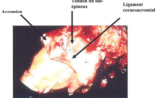
Toutefois, la morphologie osseuse de l’omoplate est telle qu’elle contraint le tendon du sus-épineux à glisser sous l’acrom ion et l’arche coracoacrornial lors de son excursion (figure 1.10). Lorsque le bras sélêve au maximum, l’insertion du tendon du sus-épineux se retrouve pincé entre la surface humérale et l’arche coracoacromial. Cet accrochage répétitif constitue un des facteurs mettant ce tendon à risque de déchirure.
Tendon du sus-épineux
Figure 1.10 : Photo de l’insertion (point bleu) du tendon du sus-épineux passant sous l’arche coracoacromial.
Lorsque la coiffe des rotateurs est déchirée de façon chronique, les tendons se rétractent et la portion musculaire s’atrophie et s’infiltre de graisse. Il devient alors impossible de rattacher les tendons à l’humérus. De plus l’infiltration graisseuse est irréversible et les muscles demeurent avec une perte de puissance significative (Goutallier, Postel et al. 1994; Goutallier, Poste! et al. 2003) (Figure 1.1 1).
Àe rm n
Ligament coracoacromial
Sus-épineux
Sous-épineux
figure 1.11: Résonance magnétique dc l’épaule droite. A- Vue antéropostérieur. Atrophie et rétraction du muscle sus-épineux (flèche vide). Contact entre la tête humérale et l’acromion (tête de flèche vide). Migration proximale du centre de rotation (flèche pointant vers le hatit). 3- Vue latérale. Atrophie sévère du sus-épineux et di.i sous-sus-épineux.
Selon Neer (1983), l’instabilité suite à une déchirure massive de la coiffe des rotateurs permet un mouvement de translation glénohumérale anormal, et une migration proximale progressive de la tête humérale (Neer. Craig et al. 1983). Cette migration résulte de l’action du deltoïde et d’une coiffe incompétente. La tête humérale se bute ultimement à l’acromion de Fomoplate. Ce contact incongru entre
A
la tête humérale et l’acrornion accélère l’usure du cartilage, altère la fonction, et accentue la douleur.
Selon des études plus récentes, la dégénérescence du cartilage de l’humérus et de la glénoïde sont en lien direct avec la présence d’une déchirure de coiffe, quoique l’étendue de la déchirure n’a pas de lien directe avec l’étendue des dommages cartilagineux (Hsu, Luo et al. 2003). Feeney (2003) a étudié 33 épaules cadavériques et observé la coiffe et les surfaces articulaires pour des changements dégénératifs. L’atteinte du cartilage était detix fois plus fréquente dans le groupe avec déchirure de coiffe (f eeney, O’Dowd et al. 2003).
À
cette explication mécanique, Neer (1983)joint une explication nutritionnelle du fait qu’une déchirure de coiffe permet
l’extravasation du liquide synovial (Neer, Craig et al. 1983). Celle fuite diminue la quantité et la qualité de l’apport nutritionnel de ce liquide, ce qui accélère l’atrophie du cartilage et de l’os sous-jacent.
Le diagnostic de l’ADC peut être confirmé par radiographie simple (Hamada, fukuda et al. 1990) (figure 1.12).
Figure 1.12: Arthropathie glénohumérale secondaire à une déchirure massive de la coiffe des rotateurs. A- Vue antéropostérieur d’une radiographie de l’épaule droite. B- Vue axiale d’une radiographie de l’épaule droite.
La migration supérieure de la tête humérale contre la surface de l’acromion est visible ainsi que le pincement de l’articulation glénohumérale. La tête humérale est habituellement déformée avec l’arrondissement de la grosse tubérosité et l’affaissement de la portion articulaire supérieure dans les cas plus avancés. L’érosion des structures avoisinantes telles l’acromion, la clavicule, et jusqu’à la base de la coracoïde peut être très importante. Le rayon x à lui setil peut confirmer le diagnostic, mais l’IRM peut mieux détailler l’étendue de l’atteinte dégénérative de la coiffe. Nove (1996) rapporte que l’étendue de la déchirure de coiffe et la dégénérescence
du
sous-épineux visible sur IRM, ont un lien direct avec la migration supérieure de la tête humérale (Nove-Josserand, Levigne et al. 1996).Étant donné que la présentation clinique de l’ACD varie selon la chronicité de cette condition, plusieurs traitements ajustés à la symptomatologie sont disponibles. Ceux-ci incluent, le traitement médical, un lavage arthroscopique (Caporali, Rossi et al. 1994) avec ou sans débridement, la tubéroplastie humérale (Fenlin, Chase et al. 2002; Scheibel, Lichtenberg et al. 2004), l’arthrodèse (Cofield and Briggs 1979; Arntz, Matsen et al. 1991), et l’arthroplastie (Coughlin, Morris et al. 1979; Post, Haskell et al. 1980; Neer, Watson et al. 1982; Neer, Craig et al. 1983; Post 1985; Field, Dines et al. 1997).
Ces dernières années et encore de nos jours, le traitement standard de l’ADC pratiqué par la majorité de chirurgiens demeure l’arthroplastie. Le soulagement de douleur et une restauration minimale de la fonction du bras permettent de reprendre
les activités de base de la vie quotidienne (Neer, Craig et al. 1983; Amtz, Jackins et al. 1993; Williams and Rockwood 1996; field, Dines et al. 1997; Zeman, Arcand et
al. 199$; Zuckerman, Scott et al. 2000; Baumgarten, Lashgari et al. 2004).
L’hémiarthroplastie, soit le remplacement de la surface humérale seulement, est préconisée par le fait que la migration proximale d’une prothèse humérale contribue au descellement précoce de la composante glénoïdienne. Ce phénomène est connu sous le nom de “rocking horse glenoid” (Franklin, Barrett et al. 198$; Baumgarten, Lashgari et al. 2004).
Dans les années 70, quelques chirurgiens ont tenté d’adapter le principe de fulcrum fixe de la prothèse de hanche à l’articulation de l’épaule. C’est-à-dire de contraindre l’articulation glénohumérale à une mécanique du type “bail and socket”. La force de traction du deltoïde est dès lors convertie en force rotative afin de permettre l’élévation du bras. Malheureusement, ce type de prothèse était voué à l’échec de par son design qui impose une force de cisaillement excessive causant le descellement de la composante glénoïdienne de son interface osseuse. Ces prothèses sont demeurées à titre expérimental et n’ont pas connu d’exploitation commerciale (Coughlin, Morris et al. 1979; Post, Haskell et al. 1980; Post 1985) (Leffin, Copeland et al. 1982).
Neer (1982) avait noté la mauvaise qualité de l’os de l’omoplate chez les patients avec ADC. Selon lui, la mauvaise qualité osseuse ne peut permettre une
fixation adéquate de la composante glénoïdienne. Il a lui-même tenté des
modifications à la composante glénoïdienne afin de contrer la migration supérieure de la tête humérale. Des composantes élargies, soient 200 à 600 % plus grande qu’une composante standard, n’ont pas apporté de succès significatif (Neer, Watson et al. 1982).
Une éttide récente de Orr (198$) à partir d’éléments finis sur des glénoïdes originales et prosthétiques, est en accord avec les principes de Neer (1982) quant au fait qu’un design contraignant a une plus grande prévalence de lignes radiolucente à l’interface os-ciment et un risque de descellement augmenté (Orr, Carter et al. 198$).
Des chirurgiens ont cherché à améliorer les résultats de l’hémiarthroplastie grâce à tine composante humérale avec une plus grande surface articulaire afin d’améliorer la congruence entre la tête humérale et l’acromion (prothèse de type CTA- Cuff Tear Arthropathy). De 2000 à 2001, Rockwood a traité 60 épaules avec ADC avec une prothèse de type CTA (DePuy, Warsaw, Indiana) (figure 1.13). En
comparaison avec l’état pré-opératoire, les résultats cliniques ont démontré une
amélioration clinique au point de vue de la douleur (4x moins de douleur),
amélioration clinique de la rotation externe (3x plus de rotation externe), et amélioration de l’élévation antérieure (2x plus d’élévation) (Visotsky, Basamania et al. 2004). Toutefois, ce type de prothèse ne peut traiter ttne pseudoparalysie déjà présente cliniquement en pré-opératoire.
Au début des années 90, le professeur Grammont a réussi à meUre de l’avant une prothèse semicontraignante de type inversée (Grammont and Baulot 1993) (figure 1.14). L’humérus est alors converti en cupule afin de recevoir une glénoïde convertie en sphère. Ce design médialise le centre de rotation glénohuméral et augmente le bras de levier du deltoïde. L’imbrication des composantes rétabli le fulcrurn au niveau glénohuméral et permet au deltoïde d’être plus efficace lors de l’élévation du bras.
Çbct1Advantage
CTA HUMERAL HEAD
La prothèse inversée permet d’éliminer la pseudoparalysie, mais ne peut toutefois redonner une force plus grande en rotation externe et interne. Différents chirurgiens ont publié des résultats cliniques sur des patients opérés avec prothèse inversée. Les indications et les limitations pour l’utilisation de cette prothèse se précisent de plus en plus (Sirveaux, f avard et al. 2004; Boucau, Watkinson et al. 2005; frankle. Siegal et al. 2005; Werner. Steinmann et al. 2005). La durée de vie de la prothèse n’est pas encore bien définie, mais des signes indirects de descellement
apparaissent très tôt autour de la composante humérale, ainsi que des signes
d’érosion du rebord inférieur de l’omoplate sous la composante glénoïdienne dès
l’année suivant l’implantation (Boileau, Watkinson et al. 2005) (McFarland,
Sanguanjit et al. 2006) (Woodruff Cohen et al. 2003; Nyffeler, Werner et al. 2004).
Depuis ce regain d’intérêt pour les prothèses semicontraingnantes, chircirgiens et scientifiques sont à la recherche d’une fixation plus durable pour la composante glénoïdienne (Ahir, Walker et al. 2004; Nyffeler, Werner et al. 2005), (Murphy and Prendergast 2005), (Harman, frankle et al. 2005). Nyffeler (2004) note lors d’un examen post-mortem huit mois après l’implantation d’une prothèse inversée Delta III, une encave prononcée au pole inférieur dci col de l’omoplate(Nyffeler, Werner et al. 2004). Cette érosion va au-delà de la vis d’encrage inférieure de la composante glénoïdienne. Cette perte osseuse correspond à l’usure de la cupule de polyéthylène.
%
L’histologie révèle une réaction à corps étrangers dans la capsule, mais aucun signe de descellement. Il poursuit son analyse dans une étude sur huit spécimens
cadavériques en testant quatre positionnements différents de la composante
glénoïdienne. Il conclut que la composante glénoïdienne fixée avec son rebord inférieur plus bas que le rebord de la surface ossetise de la glénoïde améliore significativement l’adduction et 1 ‘abduction(Nyffeler, Werner et al. 2005).
D’autres chirurgiens essaient de mieux comprendre l’impact réel du design d’une prothèse sur la restauration de la fonction. De Wilde (2004) a analysé plusieurs types de prothèses disponibles sur le marché grâce à des simulations sur ordinateur. il conclut que la prothèse inversée présente le meilleur design donnant au deltoïde le meilleur bras de levier possible (De Wilde, Audenaert et al. 2004). Néanmoins, les cliniciens suggèrent d’utiliser de cet implant avec modération, et recommande même l’implantation qtie chez les patients de 70 ans et plus, étant donné qu’un style de vie plus sédentaire diminue les risques de descellement.
Étonnamment, certains patients avec déchirure massive de la coiffe des rotateurs ne présentent qu’une douleur légère à modérée, et une amplitude de mouvement quasi complète (figure 1.15).
17
Figure 1.15: A- Patient jouant régulièrement au golf malgré des déchirures massives de coiffe bilatérales. B- Patient peu sportif avec déchirure massive de coiffe à l’épaule droite.
En effet, l’évolution clinique à long terme d’une déchirure massive de coiffe demeure imprévisible. Selon Neer (1983). environ 4% des patients avec tine déchirure de coiffe évolueront vers l’ADC étant donné que la plupart des déchirures sont petites (Neer, Craig et al. 1983). Hamada (1990) a suivi 22 patients avec déchirure massive de la coiffe traités de façon conservatrice. 5 des 7 patients suivis sur une période de 8 ans ont développé des changements dégénératifs progressifs sur les radiographies (Harnada. Fukuda et al. 1990). Dans une étude rétrospective de 25 patients avec déchirure de coiffe traités par acromioplastie et débridement par arthroscopie et suivi de 6 à 9 ans, 7 patients ont montré des signes cliniques et radiologiques d’ADC (McMahon, Debski et al. 1995).
Selon Apoil (1989). l’ADC s’ est développée chez
25%
des 56 patients 10 ans après débridement ouvert d’une DMC (Apoil 1989). Rockwood (1995) quant à lui rapporte qu’aucune épaule avec déchirure massive de coiffe sur 53 n’a montré une détérioration de l’articulation glénohurnérale après acromioplastie ouverte et débridement de coiffe. Les épaules avec suivi de moins de 5 ans ont été comparées avec les épaules avec un suivi de plus 5 ans. La détérioration fonctionnelle et radiologique n’a pu être associée au facteur temps. Chez tous les patients, les tendons du sous-scapulaire et du petit-rond étaient intacts. Tous les patients ont suivi un programme intense de renforcement de la coiffe, du deltoïde, et des muscles périscapulaires. Même si le sus-épineux et le sous-épineux étaient absents, l’effet compressif de sous-scapulaire,du
petit-rond, et l’effet stabilisatetir des musclespériscapulaires ont permis le fonctionnement actif de t’épaule (Rockwood, Williams et al. 1995).
Plusieurs auteurs s’interrogent donc sur l’effet d’une déchirure de coiffe sur la biomécanique de l’épaule (Howeli and Kraft 1991; Loehr, Helmig et al. 1994; Bigliani, Keikar et al. 1996). Encore de nos jours, aucun facteur pronostic n’a été identifié permettant de savoir avec certitude quelle épaule avec une déchirure de coiffe évoluera vers Ï’ADC.
lnman (1996) a utilisé le concept de couplage des forces “f orce Coupling” pour déterminer les forces nécessaires au fonctionnement de l’épaule (lnman, Saunders et al. 1996). Il établit que les forces musculaires dans le plan coronal proviennent du deltoïde avec une force directrice verticale supérieure et une force verticale inférieure par les muscles de la coiffe. La rotation et l’abduction sont possibles grâce à deux forces opposées agissant de chaque côté du centre de rotation. La présence et l’importance de cette force concertée des muscles antérieurs et postérieurs de la coiffe a été démontrée par étectromyographie (Saha 1971).
Burkhart (1992) a présenté des patrons de cinématique de l’épaule sous fluoroscopie (Burkhart 1992). Son analyse a permis l’identification de 3 groupes
avec fulcrum différent. Un fuicrum instable cause l’altération progressive du
couplage des forces transverse et coronale. Le degré d’instabilité correspond directement à l’étendue de la déchirure de coiffe sur le plan antéro-postérieur. Il décrit ensuite un modèle basé sur l’analogie du pont suspendu (Burkhart 1992; Burkhart, Esch et al. 1993; Burkhart, Nottage et al. 1994) (figure 1.16). La
localisation des attaches du pont suspendu sur les tubérosités résulte en une
cinématique glénohumérale stable ou instable, selon la présence d’une force de couplage transverse intacte.
Figure 1.16 : Analogie du pont suspendu présenté par Burkhart (1991). A- Schéma d’une vue supérieure axiale d’une épaule avec déchirure de la coiffe. B- Schéma d’une vue supérieure axiale d’une épaule avec superposition d’un pont suspendu.
D’autres études ont utilisé différents types de montages in vitro pour analyser la mécanique de la coiffe des rotateurs(Ovesen and Nielsen 1986; An, Browne et al. 1991; Loehr, Helmig et al. 1994; Debski, McMahon et al. 1995; Halder, Zhao et al. 2001; Kelkar, Wang et al. 2001; Parsons, Apreleva et al. 2002).
Loehr (1994) a utilisé un montage statique pour reproduire l’élévation du bras dans le plan de l’omoplate (figure 2.17). Le mouvement est simulé en déplaçant manuellement un levier inséré dans l’humérus. Ce type de montage soulève toutefois des interrogations en ce qui a trait à la reproduction de la ligne d’action de certains muscles de l’épaule, et à l’utilisation d’un humérus amputé à mi-longueur, ce qui néglige l’impact des propriétés inertielles d’un membre supérieur complet. Il parvient toutefois a démontré qu’une lésion d’aux moins deux tendons (sus-épineux et sous-épineux) est nécessaire pour déstabiliser l’articulation glénuhumérale (Loehr, HeIm ig et al. 1994).
Ovesen (1986) utilise le même type de montage, soit avec fixation de l’omoplate au niveau de la pointe inférieure (figure 2.17). Celle fixation fait abstraction du mouvement scapulothoracique et de l’inclinaison naturelle de l’omoplate retrouvés in vivo. En 1991, An et al. utilisent un système de traction par
câbles et détermine à l’aide système de positionnement magnétique l’élévation
maximale au niveau glénohumérale s’effectue dans le plan antérieur au plan de l’omoplate (An, Browne et al. 1991) (figure 2.17). Pour obtenir cette élévation maximale, l’humérus doit faire une rotation externe.
-- 1]
1
--A — 4 — — B _•,) )Figure 1.17 : Montages expérimentaux statiques. A- Ovesen (1986), Loehr (1994). B- An(1991).
Afin de reproduire plus fidèlement une cinématique normale de l’épatile, certains auteurs décrivent l’utilisation de montages dynamiques, permettant ainsi de simuler un mouvement d’élévation de façon automatisée (Debski, McMahon et al. 1995; McMahon, Debski et al. 1995; Thompson, Debski et al. 1996; Raider, Zhao et al. 2001; Kelkar, Wang et al. 2001; Parsons, Apreleva et al. 2002) (Figure 1.1$). Ces différents montages tentent ainsi de reproduire les lignes d’action des différents muscles.
r.
• •-
-Figure 1.18 (2001).
Montages expérimentaux dynamiques. A- Halder (2001). B- Kekiar
Thornpson (1996) utilise le même montage que Debski (1995) (figure 2.19). •,IÇ •
-‘-cri’ A
— -I1I.Iri.
- ilino-’
exactement les propriétés inertielles retrouvées in vivo. De plus, l’inclinaison de l’omoplate est reproduite afin de préserver un positionnement naturel au niveau glénohuméral.
Figure 1.19: Montage expérimental dynamique développé par Debski (1995).
Thompson (1996) démontre alors que des forces de couplages intactes permettent de générer une force compressive suffisante pour maintenir réduite la tête humérale et ainsi préserver une cinématique de type “bail and socket” (Thompson, Debski et al. 1996).
À
ce jour, aucune étude n’a spécifiquement analysé, in vitro, la cinématique anormale de la pseudoparalysie. Nous sommes convaincus qu’un montage expérimental, permettant ce type d’analyse, permettrait d’identifier précisément sur quels paramètres morphologiques de l’articulation le chirurgien doit intervenir poctr prévenir ou traiter la pseudoparalysie de l’ADC.Il est vrai que les prothèses d’épaule actuelles parviennent à redonner un minimum acceptable de fonction. Toutefois, le rétablissement post-opératoire demeure imprévisible, et inévitablement lié au design et à la survie de l’implant. Dès lors, nous croyons qu’une meilleure connaissance de la cinématique de la pseudoparalysie peut éventuellement mener à la conception d’tine prothèse d’épaule mieux adaptée à cette condition et favoriser un rétablissement fonctionnel maximal.
Chapitre 2: Problématique
2.1 Problématique
Premièrement. I ‘arthropathie glénuhumérale secondaire à une déchirure massive de coiffe des rotateurs (ADC) est une condition incapacitante et son traitement demeure à ce jour sous optimal. Les prothèses d’épaule présentement disponibles parviennent à soulager la douleur mais la récupération fonctionnelle est imprévisible et souvent liée à la longévité de l’implant. Il existe un besoin pour des implants mieux adaptés à cette condition.
Deuxièmement. les connaissances sur la cinématique de l’épaule en présence d’une déchirtire massive de la coiffe des rotateurs sont insuffisantes. II est donc essentiel de développer un modèle in vitro capable de simuler la pseudoparalysie de l’ADC afin d’acquérir des données de façon fiable et reproductible.
2.2 Hypothèses de travail
Lors de l’élaboration de ce travail, plusieurs hypothèses ont été sont soulevées concernant l’impact d’une déchirure de coiffe des rotatetirs sur la cinématique de l’épaule. La première hypothèse est que la déchirure massive de coiffe des t’otatetirs change le déplacement du centre de rotation glénohuméral. La seconde est que la force et la cinématique sont affectées.
2.3 But de l’étude
Le but premier de ce travail est donc de développer un montage
expérimentale in vitro permettant d’analyser la cinématique de l’articulation
glénohurnérale. Le but second est de simuler une déchirure massive de la coiffe des rotateurs et d’analyser les conséquences sur la cinématique glénohumérale à différents degrés d’élévationdu bras.
Chapitre 3: Méthodologie et situation des articles
3.1 Méthodologie
Le premier et le deuxième article de ce mémoire ont déjà été présentés dans la thèse de maîtrise de notre collaboratrice Annie Levasseitr. Ces articles décrivent la méthodologie quant à la mise en place du montage, la mise au point de la technique pour définir le centre de rotation glénohuméral, et le processus de farniliarisation avec le système de coordonnées et ses axes de référence qui permettront une analyse c inémati que.
Le troisième article décrit Futilisation de notre montage expérimental potir
étudier la cinématique anormale de lépaule causée par la présence d’une déchirure massive de la coiffe des rotateurs.
Annie Levassettr (50%) et moi-même (50%) considérons avoir contribué également à l’avancement et à la réalisation des travaux présentés dans les articles de ce mémoire.
3.2 Résultats
Dans ce mémoire sont présentés, en exclusivité, les résultats de l’analyse cinématique du troisième article.
Chapitre 4: Article I: Comparison between a geometric and a
functïonal metliod for the estimation of the glenohumeral rotation
center
A. Levassecir. P. Tétreault, .J.A. de Guise, N. Nuo. N. Hagemeister
4.1 Abstract
According to the literature, the glenohurneral rotation center (GHRC) can be estirnated using a geometric or a functional rnethod. The purpose ofthis research was to evaluate if localization and excursion of the GHRC were affected by the rnethod used. An experiment vas carried out on 8 cadaveric shoulder specirnens. The localization of the GHRC and its relative three-dirnensional (3D) excursion was analyzed using 3D imagery reconstruction and an electrornagnetic tracking device. The resuits revealed a difference in the localization of the geometric and the
functional GHRC. Sirnulated abduction motion in the plan of the scapula
dernonstrated a statistically significant difference for the GHRC excursion in the transverse plan (Z axis). Understanding the localization and behaviour of each GHRC will be valuable for future work such as the study ofcufftear arthropathy and eventual prosthetic design.
4.2 Introduction
The International Society of Biomechanics (ISB) recently proposed a definition ofajoint coordinate system to standardize shoulder joint motion (Wu. van der HeIm et al. 2005). This coordinate system ‘as developed using bony landrnarks on the scapula and humerus and the glenohurneral rotation center (GHRC). Being a reference landrnark for shoulder joint motion analysis, the GHRC needs to be localized precisely. Its position relative to the scapula is very important for the stability of the joint, which is assurned to act as a ball-and-socket (HeIm, Veeger et al. 1992; de Leest, Rozing et al. 1996). Changes in the position ofthe GHRC could ultimately affect estimation ofthe lever arms ofthe muscles and therefore modify the interpretation of shoulder kinematics.
Three different methods have been described to estimate the GHRC: geometric method, regression equation method. helicoidal axis rnethod, pivoting algorithm. The geometric method estirnates the GHRC as a sphere fltted through the glenoid surface with a radius based on the size ofthe humeraI head (Helm. Veeger et al. 1992). Witti the regression equation method. the GHRC is estimated as the center ofthe best-filled sphere on the glenoid and hurneral head (Meskers, van der HeIm et al. 1998). The helicoidal axis method and the pivoting algorithrn estirnate the GHRC
as the optimal pivot point ofthe humerus relative to the scapula during a movement ofthe arm (Woltring 1990: Siston and Delp 2006).
The rnethods used to estimate the GHRC can be classifled in two general categories: geometric (based on the bone geometry) or functional (based on the bone movement) (de Leest. Rozing et al. 1996). To the best of our knowledge, there is no
in vitro study that compares the different methods in terms of localization and excursion ofthe GHRC during movement ofthe arm. Therefore, theaim ofour study was to determine the GHRC on cadaver shotilder specimens, using a geometric and a functional method, and to compare their relative localization, their excursion during the abduction motion of the arrn and their localization with respect to the center of the glenoid.
4.3 Material and Method
4.3.1 Specimen preparation
Eight fresh-frozen cadaver shoulder specirnens including entire arm were used (4 lefts and 4 rights, age range 59 to 87 years). The specimens were stored in a freezer at -20°C and thawed at room temperature for approxirnately $ hours before the dissection. Ail soft tissties were removed except the rotator cuff muscles, deltoid, capsule and ligament structures. The cadaver specirnens did not show any musculoskeletal pathology. Two aluminium triangles were fastened with plastic screws on the scapula and the hurnerus for calibration purposes. After dissection, the specimens were refrozen and then sent for CT scan. From the CT images, a 3D reconstruction of the shotilder was performed with the help of a commercialized softwate (SI iceOrnatic.Tornovision, Canada).
4.3.2 Testing device
A testing device made of an abduction guide and two mounting blocks was
used to test each shoulder specirnen (Figure 4.1). It was etitirely made of wood to avoid interference with the tracking device (Fastrak. Polhemus, USA) used to measure shoulder movernent. The abduction guide was shaped like a quarter of arch and controlled elevation ofthe arm in the scapular plane. The main mounting biock
abduction guide. The other block was linked to the main block and used to lix a pulling mechanism, which consisted of an electric cylinder (NV-D Series). This rnechanism simulated a contintious motion at constant speed with minimal friction. A force transducer (RL 20000 5 beam) was fixed at the tip ofthe ptilling mechanism to a fabric strip that simulated the rniddle deltoid function during ami elevation.
Figure 4.1 : Testing device composed of 2 mounting blocks (A,B); a support for the tracking device (C); a guide (D); and an electric cylinder (E) equipped with a force transducer (F) and positioning ofthe scapula: (a) scapula guiding device, (b) fabric strip, (e) sensors and (d) transmitter ofthe electrornagnetic tracking device.
4.3.3 Experïmentation
Prior to the experirnent, each specirnen was thawed at room temperature for a period of 12 hours. To immobilize
th
motion of the forearm, the elbow was flxed with a brass screw. The scapula was mounted on the testing device and positionedsuch that the medial border of the scapula was perpendicular to the ground. The middle deltoid was resected and replaced by a strip of non-elastic fabric (Figure 4.1). One extremity ofthe fabric strip was fixed to the deltoid tuberosity, and the other to the pulling mechanisrn. To prevent siipping of the fabric strip off the acromion, a guiding device was attached on top of the scapula (Figure 4.1). This device also helped in reproducing the uneofaction ofthe middle deltoid muscle.
The shoulder joint motion was recorded using an electrornagnetic tracking device (Fastrak, Polhemus, USA) (Figure 4.1). The accuracy ofthe system is lrnrn
for linear dispiacement and 0,1° for angular dispiacernent. Sensors were screwed on plastic plates. which were directiy flxed on the scapula and hurnerus. The sensor on the scapula served as a control for possible movement of the testing device. A
personai computer with custorn-design software recorded the three dirnensional dispiacernent ofthe ami at 60 Hz in real time.
Before data acquisition. the effect of the environment on the accuracy of the tracking device was evaluated. Then, a calibration procedure vas perforrned which consisted in digitalizing the extrernity of both triangles fastened on the scapula and
the hurnerus using a Fastrak pointer. This procedure aliowed estabiishing a
transformation matrix between the motion of the cadaver specirnen and the virtual 3D reconstruction. Thereafter, 25 passive abduction movements were carried out with the pulling mechanism to condition the specimen and to minirnize the viscoelastic effect of the soft tissues(Debski. McMahon et al. 1995: Thompson. Debski et ai. 1996; Parsons. Apreleva et ai. 2002).
Circumduction movements of the arm were perforrned by the experimenter over a 30-second period. The experimenter tried flot to press the humerai head into the glenoid and not to move the arm beyond the active normal range of motion.
Afterwards, J O abduction movements of maximal range of motion were compieted
using the pulling mechanisrn. Each trial lasted 10 seconds. During experimentation, the specimens were kept rnoist with saline solution. Afterwards, the specirnen was restored in the freezer at -20°C.
4.3.4 Method used for determining the geometric GHRC
First, the geometric GKRC was estimated using the 3D computed geometric moUd of the hurnerus. A point cloud was seiected on this model tising the software
caÏled Poiyworks (lnnovMetric, Canada) (Figtire 4.2). It corresponds to the articuiar surface of the humerai beaU and has the shape of haif a sphere (figure 4.2). The
seiection was made rnanually three times by one person. A sphere vas then fltted by
a least square rnethod to the data of the point cioud (Figure 4.2). The center of this sphere corresponded to the geometric GHRC.
I
a) e)
r
-Figure 4.2: (a) Selection of point cloud on the 3D reconstruction ofthe humerai head (b) point cioud; (c) sphere estimated by a ieast square method
4.3.5 Method used for determining the functional GHRC
To estimate the functionai GHRC. the rnethod presented by Sinston and Deip was used(Siston and Delp 2006). By a ieast square method, the GHRC was estimated as a flxed pivot point relative to the scapula during a circurnduction movement.
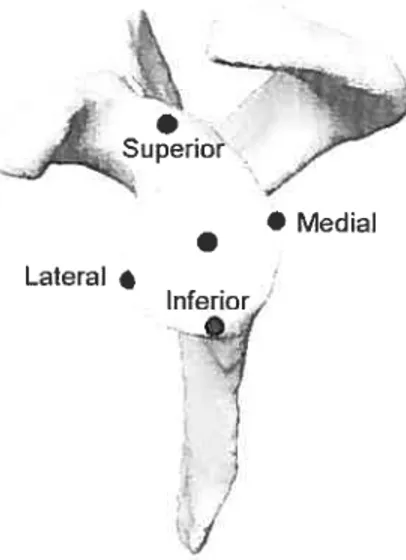
4.3.6 Method used for determining the glenoid center
The gienoid center was determined using the 3D computed mode! of the scapuia. The superior, inferior, meUlaI and iaterai edges ofthe glenoid were iabelled with a custorn-design computer graphics software (Figure 4.3). The center ofthe une joining the superior and inferior edges ofthe glenoid fossa deflned the gienoid center in the frontal plane, whiie the media! and iateral edges deflned the gienoid center in the sagittal plane.
• Medial Lateral
•
Inferior
r
J
Figure 4.3: Glenoid center determined with the superior, inferior, media!, and lateral edge ofthe glenoid fossa
4.3.7 Shoulder joint coordinate systems to localize and compare the
dispiacement ofthe geometric and functional GHRC
The shoulder joint coordinate system used two local coordinate systems: one on the scapula and the other on the hurnerus. Both local coordinate systems were set by using bony landmarks, as defined by the ISB (Table 4.1) (Wu, van der Helrn et al. 2005).
flony landmarks for the definition of local coordinate systems
Anatomical Description Landmark GH RC EL EM Table 4.1: Bone
Hurnerus GlenoHumeral rotation centerMust caudalpointon Lateral Epicondyle Most caudal pointonMedia! Epicond le Scapula AC Most dorsalpointon the Acrornioclavicular joint
IS [riogonum Spinae Scapulae. rnidpoint of triangular surfaceon rncdial border ofthescapula in lincwith the scapular spinc
AI Angultis Interior. rnost caudal point ofthe scapula AA Angulus Acrornialis. rnost latero-dorsal point oC the scapula
()
AA. pointing to AA. The X axis is deflned as the une perpendicular to the plane forrned by Al. AA and TS. It is pointing forward. The Y5 axis is the common line perpendicular to X, and Z. and pointing upward.
“ti
II
EM
Figure 4.4: Reference and moving coordinate system
The moving coordinate system is positioned at the GHRC ofthe hurneriis
()
(Figure 4.4). The Y11 axis is deflned as the une connecting GHRC and the midpoint of EL and EM pointing to GHRC. The Xh axis is defined as the fine perpendicular to the plane forrned by EL. EM and GHRC. It is directed forward. The Zh axis is the common une perpendicular to Y11 and X11 pointing to EL. The motion ofthe hurnerus is described with respect to the scaptila coordinate systems using Euler angles (X11. Z11, Yi1). Dispiacement ofthe geometric and functional GHRC was calculated relative to the AA point on the scapula along 3 axes (X5, Y5, Z5).4.3.8 Statïstical analysis
A two-way ANOVA for repeated measures vas perforrned to determine if there was a difference in displacement between the geornetric and ftinctional GHRC during an abduction movement. Statistical significance was set at p < 0.05. AIl analyses were performed using the SPSS software.
4.4 Resuits
The three-dirnensional coordinates ofthe geometric and functional GHRC for each shotilder specimen are presented in table 4.2. The coordinates of the glenoid centers for each specimen in the sagittal frontal and transverse planes are also displayed. Ah these data represent the actual distance in mm of the GHRC and the glenoid center from the AA point on the scapula along the X, Y, Z.
Table 4.2:
Coordinates ofthe: geometric GHRC. functional center with respect to AA point on the scapula.GHRC and glenoid
Geometric GHRC fuitctional GHRC GlenoidCenter
Specimens X (inni) Y (mm) Z(,ii,ii) k (mm) Y (nim) Z (mm) .‘ (mmmi) Y (mmimn) Z (nim)
39.1 -19.t) 0.0 1 45.7 -26.7 13.7 40.6 -33.8 12.5 ±0,2 ±0.8 ±0.4 ±0.2 ±0.8 ±0.3 2 37.2 -32,0 4.4 36.4 -35.1 1.2 ±0.2 ±0.5 ±0.2 ±0.1 ± 0,5 ±0.2 3 47.0 -17.3 10.3 45.9 -22.3 7.9 ±0,1 ±0.1 ±0,1 ±0.1 ±0.1 ±0,1 4 31.0 -27.7 5.2 29.9 -29.9 8.2 ±0.4 ±0.2 ±0. I ±0.4 ±0.2 + 0.1 5 16.7 -23.6 3.4 49.8 -22.4 1.4 ±0.2 ±0.1 ±0.2 ±0.2 ±0.1 +0.2 6 48.5 -21.5 -3.3 50.6 -29.0 -6.6 ±0.7 ±0.4 ±0.2 ±0.7 ±0.4 ±0.2 7 47.1 -36.7 11.7 36.8 -48.6 10.2 ±0.1 0.1 ±0.0 ±0.1 ±01 ±0.0 8 38.4 -16.3 -1.7 45.0 -20.9 -6.0 ±0.0 ± 0.2 ±0.1 ±0.0 ±0.2 ±0.1 42.7 -25.6 5.4 41,9 -30,3 3.6 ± 6,3 32.7 -20,8 0.0 41.6 -12,4 0.0 28.1 -20.7 0.0 36.9 -19.3 0.0 37.2 -2 1.5 0.0 36.3 -22.1 0.t) 27.1 -16.8 0.0 Meami +6.9 ±6.] ±7.2 ±9.1 ±7.3 ±5,2 ±3.2 +0.0 34.9 -19.] 0.0
Referring to Table 4.2, both GHRC were positioned below and in front oftbe reference Iandmark AA (Figure 4.5). For the rnajority of specimens, the GHRC was positioned on the lateral side ofAA except for specimen 6 and 8, where both GHRC were positioned on the media! side of AA landmark. Relative to the geornetric rotation center, the ftinctional rotation center was lower (4,7 mm) and rnediaIly (1,8 mm) positioned.
The excursion ofthe geometric and functional GHRC during abduction ofthe arm was calculated. The excursion was defined as the difference between the final and the initial position of the GHRC. Figure 4.6 presents the mean excursion of the geometric and functional GHRC during an average abduction movernent of 32,9 + 7,00.
Figure 4.5: Localization ofthe geometric (G) and functional (F) GKRC for specimen #7.
*
For the geometric GHRC. its excursion varied between 0.3 to 6.2 mm. 2.0 to 16,3 mm and 0,3 to 3.7 mm in the X. Y and Z axis. respectively. For the functional GHRC, its excursion varied between 0,1 to 5,7 mm, 1,43 to 15,5 mm and 0,4 to 5.9 mm in the X. Y and Z axis. respectively. Based on the statistical analysis, excursion of the geornetric and functional GHRC did flot differ significantly in the X and Y axis. However, there was a statistically significant difference for the excursion in the Z-axis
(p0,027).
The functional GHRC moved further lateral relative to the AA point and the geometric GHRC moved further media! to the AA point (f igure 4.7).At resting position, the distance between both GHRC averaged 3,8 ± 3,4 mm (range 0,8 to 10,3 mm), 5,0 + 3,3 mm (range 1,2 to 11,9 mm) and 2,6 + 1,0 mm (range 1,2 to 3,3 mm) in the X, Y and Z axis respectively. In maximum abduction, this distance averaged 3.6 + 3,2 mm (range 0,2 to 8.6 mm), 4.8 ± 4,0 mm (range 0.4 to 12,7 mm) and 2.4 + 1.6 mm (range 0.4 to 5.1 mm) in the X. Y and Z axis respectively. 14,0 -12,0 -10,0 -E 8,0-E 6,0
-Eh
z AxisFigure 4.6: Mean displacernent ofthe geometric (plain stick) and functional (lined stick) GHRC.
--15 -20 C o - -30-En >-35_, S1r1 -40 40 4 X P:hr’ oe— AA 20 -30 20 20 — o O Z Po.tcn
Figure4.7: Mean 3D excursion ofthe geornetric (grey une) and functional (black une) GHRC relative to the AA tandmark for specimen #7.
The distance between the glenoid center and both GHRC (geometric and functional) was calculated in the resting position of the arrn and at the maximtirn abduction (Figure 4.8). This distance vas deflned as the vectorial sum of the distances between the glenoid center and the GHRC in the sagittal and frontal plane. In the resting position. the distances averaged 11, 1 ± 3,4 mm (range 7.3 to 1 8,2 mm) for the geometric GHRC and 15,4 + 5.3 mm (range 9,4 to 26,5 mm) for the functional GHRC. In maximum abduction, the distance averaged 8,2 + 5,3 mm (range 0,8 to 17.0 mm) for the geometric GRRC, and 11,1 ± 6,3 (range 0,6 to 20,7 mm) for the functional GHRC.
E E
25,0
Figure 4.8: Mean distance between the glenoid center and the GHRC determined with the geometric (plain stick) and functional (lined stick) rnethod.
4.5 Discussion
Our resuits show a difference between the position of the geometric and
functional GHRC. These findings are in contradiction with Veeger (Veeger 2000),
who found that the kinematic rotation center is flot statistically different from the geometric center. This can probably be explained by the natitre ofthe movement and the mathematical algorithrn used to determine the ftinctional GHRC. First, Veeger moved the humerus in three directions: abduction-adduction, flexion-extension, and internal-external rotation. The author did flot execute a multiplan motion (i.e. circumduction motion). As Siston and Delp has shown, the srnallest mean errors in
determining the joint center occur with a circurnduction motion pattern, while the largest errors occur with single-plan motion(Siston and Delp 2006). Therefore, Veeger’s estimation of functional GHRC was flot optimal because it omitted motion planes. Second, Veeger cised the instantaneous helical axis (IHA) to calculate the functional GHRC, even if this method produces a large non-systematic error when
estimating kinematic rotation center. Woltring (1990) bas shown that the IHA
calculations are extremely sensitive to errors when the rotation speed is small and the data noisy(Woltring 1990). Unlike Veeger, the pivoting algorithm was used in our
study. According to Siston and Delp, the pivoting algorithm «is an accurate technique to locate thejoint centerwhich is minimally affected by reasonable limits
of motion and the presence ofnoisy motion data».
20,0
10.0
5,0
The difference observed between the two GHRC in our study cannot be explained by the fact that the movernent vas carried out by an experimenter. In fact. the variability in GHRC localization vas eqtiivalent for both geornetric and functional methods. For this reason. the way the circumduction movement was performed by the experimenter cannot be deerned to have had a significant impact.
it bas long been assurned that the normal glenohumerai joint acts as a bail and-socket joint with a fixed rotation center even though the rotator cuff is present but non-functional (Howeil and Galinat I 989 Veeger 2000). «As long as there is a compressive force acting, the intact glenohurneral articulation would be expected to be stable and tuehumerai head wiil rotate on a more or less fixed centerwith little, if any excursion (Poppen and Walker 1976)». If we base oui’selves on this affirmation, the GKRC shoutd be Iocalized at a point where its excursion is minimal during motion of the arrn. Accord ing to Thornpson (Thompson. Dehski et ai. 1996) and Kekiar (Keikar, Wang et ai. 2001). the humerai beaU translation shotiid be lower than 2 or 3 mm for a sirnuiated abduction movement of at ieast 90°. In the same wav. Wuelker and al. (Wueiker. Scbmotzer et al. 1994) repoiÏed that the translation ofthe humeraI head rotation center for a 30° abduction of the arrn averaged 3.6rnm ± 3,3mm superiorly and 0,Omm ± 23 anteriorly. Our results revealed that both GHRC rnoved between 7,1 + 4,4 and 2.7 + 1,8 mm during ahduction of the arrn. We reported iarger displacernent than previous published reports. This difference could be attributed to the initial position of the humerai beaU used for reporting the excursion. Unlike the present study. Thornpson (Thornpson, Debski et al. 1996) and Wuelker (Wueiker, Schmotzer et al. 1994) applied a small amount of upward forces (5N/N-m vs 23N + 4,6N) on the arrn at the beginning ofeach experirnent. This force application consequently annihilates the effect of gravity and prevents the ami from subluxating inferiorly. Consequently, a srnaller exctirsion vas recorded. As to Keklar (Kelkar. Wang et al. 2001), « the position ofthe center ofthe humerai head at 90° vas taken as a reference position for repoiling humeraI head translation. The position of 0° was not selected as a reference position because ail joints had been vented and. as such. sublLtxated inferiorly at 00».
The excursion ofthe geometric and functionai GHRC recorded in the present study during abduction of the arm tends to dernonstrate that the glenohumeral joint
does flot behave only as bail and socket joint bctt in a more compiex wav. The gienohurneral joint does not have a flxed rotation point because rotation and translation occur sirnultaneously. Moreover, it vas observed that excursion pauerns differed for geometric and functional GHRC. During an abdtiction movement ofthe an-n, the ftinctional GHRC had a greater medial to lateral dispiacement than the geometric GHRC. However. the distance between both the geometric and functional GHRC stayed approximately the sarne with motion in the scapular plane.
Several studies have docurnented that the humerai head was precisely centered in the glenoid fossa. Poppen (Poppen and Waiker 1976) and Howeil (Howeil and Galinat 1989) dernonstrated in vitro that the center ofthe humerai beaU remained within Imm ofthe center ofthe glenoid throughout the elevation of the arm. Biornechanical models of the shoulder joint were furthet devetoped based on this assumption. In the present study, the functionai and geornetric GHRC were not centered on the gienoid. The distance between the gienoid center and the geometric and functional GHRC varied between 11,1 ±3.4 mm and 1 5,4± 5.3 mm respectiveiy. The difference observed is probably due to die rnethodoiogy used in the present study and the anatomy ofthe glenoid fossa. First, Poppen (1976) and Howeli (1989) had used roentgenograrn to calculate the distance between the geometric center ofthe hurnerus and the center of the glenoid. This type of imaging technique gives information only in one plane. Unlike them, the localisation ofthe GHRC relative to the glenoid center combined two planes (sagittal and frontal). If we consider only the frontal plane, a mean distance of 6,7 +4,5 mm was calculated between the geometric
GHRC and the glenoid center. This higher value to the one observed by Poppen could be explained by the fact that the rotator cuff muscles were inactive. Poppen’s research was donc on living subjects while ours donc made on cadaveric specimens. Second. anatornicai studies have indicated that the articular surface of the glenoid fossa forms only one third to one quarter ofthe humerai head articular surface (Low and Reed 1 996: Terry and Chopp 2000). According to Terry, the humerai head is in contact with only 25-30% ofthe glenoid cavity in ail situations. Therefore. the smail surface area of the glenoid does not enclose the humerai head. Being a joint with minimal bony constraint, the glenohumeral joint may consequently not be centered perfectiyon the glenoid fossa inail three planes despite the presence ofthe labrum.
4.6 Conclusion
The GHRC is a very important landmark. It is a reference for the shoulder
joint motion analysis and bas to be localized preciseiy. In our study, the geometric GHRC and the functional GHRC were flot localized at the sarne point and did not behave in the same way with motion. Because the hurnertis head rotated and transiated on the gÏenoid, the assumption that the shoulder is a bail and socket joint is open to question. Consequently. future kinematics analysis must take into account the behaviour of geornetric and functional G1-IRC. These findings coutd eventually be applied to conditions stich as rotator ctiff tear or ctiff tear arthropathy. Therefore. it is possible to speculate that in the presence of a rotator cuff tear. geornetric and functionai GHRC move further apart because the stabilisation rnechanism provided by the muscles is disturbed. Clinically. the dissociation between the geometric and functional GHRC could manifest itself in a loss offunction, such as psetidoparalysis
due to the rotator ctiff rupture. in conclusion, this study demonstrates that ttiree dimensional analysis can be usefui in providing additional information in comparison with two-dirnensional analysis.
4.7 Acknowledgement
The authors would like to acknowledge CRSNG and FQRNT for funding.
Chapitre 5: Article
II:
Simplification of the ISB joint coordinate
system to describe shoulder joint kinematics
A. Levasseur. P. Tétreault, J.A. de Guise. N. Ncio. N. Hagemeister