E. Mersch and N. Vandewalle GRASP, Institut de Physique B5, Universit´e de Li`ege, B-4000 Li`ege, Belgium.
When a spherical conducting bead is placed in an electrode, it experiences an electric force. In a plane ca-pacitor, it can undergo a periodic bouncing between the electrodes. Using a fast video camera, we measured the acceleration of the bead and the period of its motion as a function of the applied voltage. A mathematical model based on the hypothesis of electrostatic equilibrium is proposed to describe the dynamics of the system. We observe a stabilization of the trajectories : a bead bouncing between two electrodes tends to oscillate on a quasi-vertical trajectory, whatever its initial horizontal velocity. When two identical beads are placed together in a capacitor, they oscillate at the same frequency and an anti-phase synchronization effect occurs. We propose a simple mechanism based on a Kuramoto-like model to explain it.
PACS numbers: 45.70.-n, 45.50.-j, 05.45.Xt, 41.20.Cv
Introduction
When micron or millimeter-sized objects are placed in contact with an electrode, they can experience forces larger than their weight. The dynamics of a conducting bead immer-sed in a poorly conducting liquid inside a horizontal plane ca-pacitor submitted to a DC voltage was studied by Khayari and coworkers [1]. When charged on the bottom plate, the ball is pushed in the upward direction. After its discharge through the liquid, the it goes back down to the bottom electrode because of gravity. The system exhibits a periodic dynamics. The same experiment was conducted with an additional alternating elec-tric field [2]. When increasing the amplitude of the alternating electric field, the system exhibits a period-doubling bifurca-tion analogous to the one observed for a ball mechanically shaken on an horizontal plate.
For a larger number of particles, the mutual interactions are responsible for some fascinating collective behaviors. Saint Jean and coworkers studied the diffusion of millimeter-sized spherical conducting particles placed between electrodes of different geometries and submitted to a mechanical shaking. They used this system to study the structure and the mel-ting of small Wigner crystals in 2D [3–7]. They also studied the single-file diffusion problem within this system [8–10]. Aranson and coworkers[11–19] studied some collective beha-viors of large assemblies of conducting beads and glass beads of various diameters enclosed in plane capacitors. They stu-died the formation dynamics of clusters and could apply the attachment-detachment-controlled Ostwald ripening theory to describe it [11–15]. They studied the velocity distributions of this far from equilibrium system [16] as well as some pat-tern formation when micron-sized conducting spheres are im-mersed in a poorly conducting liquids in the presence of a dc electric field [17–19]. Zhand and Liu studied the effect of an alternating electric field on a very similar experiment [20].
In this work, we focused our attention on a minimalist ver-sion of the experiment of Aranson and co-workers. We studied the behavior of a single, two or three spherical conducting beads submitted to a constant and homogeneous electric field. In sectionI, we describe our experimental setup. The section
IIis dedicated to the problem of a single bead. In sectionIII, we discuss the dynamics of two interacting beads.
I. EXPERIMENTAL SETUP
A sketch of our experimental setup is shown in Figure1. One, two or three spherical beads are placed between two ho-rizontal plane electrodes. For the experiments conducted with a single bead, we used two glass beads with respective diame-tersd = 400 µm and d = 488 µm coated with a conducting layer as well as a steel bead of diameterd = 500 µm. For the experiment with two or three beads we used two stainless steal beads with a diameterd = 2 mm. The plates of the capacitor are two parallel square with an edgeD = 60 mm separated by a fixed gaph = 3 mm. A DC voltage V comprised between 0 and 5000 V is applied to the electrodes. The cell is open in an atmosphere of controlled humidity (43%RH) at ambient pressure and temperature. The choice of this humidity is mo-tivated by a recent work [21] demonstrating a minimum of bead-bead cohesion induced by capillary condensation when RH ≈ 40 − 50 %. A fast CCD camera records the trajec-tory from the side at a frame rate ranging between 500 and 6000 fps.
FIG. 1: Sketch of the experimental setup. One or two spherical
conducting beads are placed between two horizontal plane electrodes plugged to a high voltage power supply. A fast CCD camera and a tracking algorithm are used to record the trajectory of the beads.
II. DYNAMICS OF A SINGLE BEAD A. Experimental results
At the beginning of the experiment, the bead is placed in contact with the bottom electrode. If the applied electric field is large enough, the particle can detach and accelerate in the direction of the upper electrode. It collides with this electrode. During the bouncing, the bead charges with the opposite sign and it further accelerates in the opposite direction. A periodic motion with a limit cycle is thus reached. The Figure2 repre-sents the vertical coordinatez of a 488 µm coated glass bead as a function of timet. The applied voltage V is 2000 V and the frame rate is 6000 fps. The limit cycle is reached after about 10 collisions, which correspond to 50 ms.
0.0 0.5 1.0 0 20 40 60 80 100 120 140 160 z/(h-d) Time (ms)
FIG. 2: Temporal evolution of the vertical coordinate z of a single
coated glass bead of 488µm under 2000 V. z is normalized by h − d
in order to obtain values in the interval [0,1].
We recorded the trajectories of a single 400µm coated glass bead. We measured its acceleration for different voltage va-lues. We obtained the accelerationa due to the electric force by subtracting the gravitational accelerationg = 9.81 m s−2. The Figure 3 shows the accelerationa as a function of the applied voltageV . Each dot is an average of 5 samples. The acceleration increases with the voltageV in a quadratic way (see model in sectionII B). The accelerationa reaches values up to 25g. Three regions denoted I, II and III correspond to three dynamical regimes described in sectionII B.
0 50 100 150 200 250 0 1 2 3 4 5 a (m.s -2 ) V (kV) I II III
FIG. 3: Measured accelerationa of a coated glass bead of 400 µm .
The solid curve represents the Eq.(4), without any fitting parameter. Three regions I, II, III represent three dynamical regimes described
in sectionII B.
We measured the periodT of the limit cycle of a 488 µm
coated glass bead. The Figure4 presents the periodT as a function of the applied voltageV . Each dot is an average com-puted over 20 to 50 oscillations. As expected form the above observations, the period decreases with increasing voltage.
0 5 10 15 20 0 1 2 3 4 5 T (ms) V (kV) I II III
FIG. 4: Measured periodT of the limit cycle of a coated glass bead
of 488µm. The solid curve represents the Eq.(6) without any fitting
parameter. Three regions I, II, III represent three dynamical regimes
described in sectionII B.
When a horizontal velocity is given to a bead bouncing on the bottom plate, it keeps a finite horizontal velocity for a long time. On the other hand, when a bead bounces alternatively on both plates, it rapidly reaches a quasi-vertical oscillation. A horizontal stabilization effect occurs for a bead bouncing alternatively on two facing plates (see Figure5). The mecha-nism for this stabilization is not trivial. However, we can un-derstand that when a bead is bouncing between two plates, the couple of the friction force can change of sign at each bounce and tend to reduce the rotation of the bead. This is not the case for a bead bouncing only on the bottom plate.
By drawing a mark on the beads, we could observe their rotation. When a bead is bouncing between two plates with a non zero horizontal component of velocity, its angular rotation speed is initialy of the order of 15 rad/s. During the collisions, the sign of angular rotation can change. After a few collisions, the angular velocity vanishes rapidly. However, when the bead is bouncing on the bottom plate only, the sign of the angular rotation remains unchanged. The angular velocity slowly va-nishes.
This effect was already reported by Leconte and cowor-kers [26] for a bead mechanically shaken between two parallel plates. They took advantage of this to make precise measure-ments of the normal restitution coefficient of a steal bead. It also plays a crucial role for the experiment described in the sectionIIIof this article.
B. Mathematical description
In the following, we will suppose that the charging time of the conducting bead is shorter than the time of contact with an electrode. This means that the electrostatic equilibrium is rea-ched during each contact. The damping due to viscous friction with air is negligible.
0.0 0.5 1.0 0 1 2 3 4 5 6 7 8 z/(h-d) x/(h-d) 0 0.2 0.4 0 1 2 3 4 5 6 7 8 z/(h-d) x/(h-d) 0 0.2 0.4 0 1 2 3 4 5 6 7 8 z/(h-d) x/(h-d)
FIG. 5: Horizontal stabilization of a bouncing bead. The
horizon-tal velocity of a bead bouncing on the bottom plate is slowly redu-ced (top picture). The horizontal velocity of a bead bouncing bet-ween two plates is rapidly reduced and the trajectory becomes quasi-vertical (bottom picture). Both pictures correspond to the same bead, to the same applied voltage, and the same video length.
FIG. 6: When a bead is in contact with an electrode, it experiences
its weight and a forceFc given by Eq.(1). When it is far from the
electrodes, it experiences its weight and an electric forceFagiven
by Eq.(3).
First let us calculate the forceFcthat acts on a bead when it is in contact with an electrode. If the diameterd of the bead is small compared to the gaph between the electrodes, we can refer to the problem of a sphere in contact with a plane placed at the same electric potential. According to Maxwell [22],Fc reads
Fc= πcǫ0d 2
E02
, (1)
whereǫ0is the vacuum permittivity,E0= V /h is the applied electric field,ρ the density of the bead and d its diameter, c ≈ 1.36 is an integration constant. If this force is larger than the weight of the bead, it can not stay on the bottom plate and it reaches the limit cycle. The critical electric fieldE2 for this force balance is given by
E2=r ρgd 6cǫ0
. (2)
This expression was used by Aranson and co-workers, and it appears as a critical value on the phase diagrams of several experiments conducted with a large number of particles [11– 14]. When the bead accelerates between the electrodes, it ex-periences an electric forceFa. This force is not anymore given
by Eq.(1). If the diameterd is small compared to the gap h, we can consider that during the trajectory between the electrodes, the bead is submitted to a force of the form :
Fa= qE0,
whereq is the total charge on the bead. The exact expression of this charge has been calculated in [22]. We use it to express Faas Fa = π3 ǫ0d 2 E2 0 6 = π2 6cFc. (3)
A more accurate expression of the force acting on a conduc-ting sphere close to a plane electrode can be found in [23]. The forcesFa andFc are sketched in Figure6. When the bead is going upwards, it is submitted to an accelerationa − g, where g is the gravitational acceleration. When it goes downwards, it is submitted to an acceleration−a − g. The acceleration a due to the forceFareads
a = π 2
ǫ0E02
ρd . (4)
After some collisions, the bead reaches a periodic limit cycle. During one period of this limit cycle, the energy given by the work of the electric force is counterbalanced by the energy dissipated during the collisions. The period T of the limit cycle can therefore be expressed as
T = √ 2 a + g − e√2 a − g ! r (h − d)(a + g + ae2 − ge2) 1 − e4 (5) + √ 2 a − g − e√2 a + g ! r (h − d)(a − g + ae2+ ge2) 1 − e4 . Ifa ≫ g, T can be expressed as T ≈ √ 8 π s 1 − e 1 + e ρd(h − d) ǫ0E0 2 . (6)
The limit cycle can still be stable ifFc < mg. There is ano-ther critical fieldE1below which the limit cycle becomes uns-table. This critical electric field writes
E1= s 1 − e2 1 + e2 ρgd π2 ǫ0 =r 1 − e 2 1 + e2 6c π2E2. (7)
The dynamics of the system is therefore determined by three regimes :
– In the region I (E0 < E1) : the only stable attractor is a fixed point : the bead stays on the bottom plate.
– In the region II (E1 < E0 < E2) : they are two stable attractors : a periodic limit cycle and a fixed point. – In the region III (E0 > E2) : the fixed point loses its
stability and the limit cycle is the only stable attractor. The predictions of this model are respectively plotted in Figures 3 and 4. The accelerationa (Eq.(4)), the periodT (Eq.(6)) and the critical electric fields E1 and E2 (Eqs.(7) and (2)) are predicted without fitting parameter. We used ρ = 2500 kg m−3,d = 400 µm and d = 488 µm. The nor-mal restitution coefficiente = 0.905 was measured indepen-dently. The valuesE1andE2were measured for a steel bead of diameterd = 500 µm. The value E2is correctly predicted by Eq.2. The experimental value ofE1is however larger than the one predicted by Eq.7. When decreasing the electric field aboveE1, small fluctuations of the bead velocity may cause the loss of stability of the oscillations. Experiments and theory are in agreement. The small deviations of the master curve in Figure4is probably due to an effect of projection due to the position of the camera.
The dynamics of a single bead electrically shaken is more simple than the dynamics of a bead mechanically shaken bet-ween two oscillating plates. Only two attractors are observed for electrical shaking, whereas bifurcation cascade and chao-tic orbits are expected for mechanical shaking [24,25].
III. DYNAMICS OF SEVERAL INTERACTING BEADS A. Two beads
In this section, we describe the experiment of two neigh-boring identical beads in a capacitor. The beads are stainless steel beads with a diameterd = 2 mm. The applied voltage V is 2000 V. The frame rate of the video camera is 2000 fps.
Figure7 shows a typical evolution of the heightz of two neighboring beads. The beads oscillate with the same fre-quency, and after few collisions with the plates, they get in phase opposition. The horizontal stabilization effect described in sectionII Ais crucial for this experiment : both beads need to keep a constant frequency and to stay close to each other to become anti-synchronized.
In order the measure a phase shift between the experimental trajectories of the beads, we defined the following parameter :
φ(t) = cos−1 h(z1(t) − z1) (z2(t) − z2)iT r D (z1(t) − z1) 2E T D (z2(t) − z2) 2E T
where zi designates the vertical coordinate of the bead i, i ∈ {1, 2}, zi the average ofzi over all the total length of
0.0 0.5 1.0 400 450 500 550 600 650 z/(h-d) Time (ms)
FIG. 7: Temporal evolution of the vertical coordinate of two
inter-acting steal beads of 2 mm diameter under a voltage of 2000 V. The beads oscillate at the same frequency and get in phase opposition.
the video, and the brackethf(t)iT denotes the mobile average RT
0 f (t + τ )dτ of the function f over one period T .
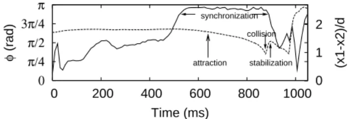
Figure8illustrates the temporal evolution of the phase shift φ and the horizontal separation x1− x2 between the beads. The total time of the sample shown in this picture (1050 ms) corresponds to 75 oscillations. After some time,φ reaches a horizontal plateau, indicating a phase locking at a phase shift ofπ. When the beads are synchronized, they are attracted by each other and they undergo a collision. After the collision, the separation between the beads is rapidly stabilized and they undergo a second collision. This is the sign of the stabilization effect described in sectionII A. This behavior is typical for a system of two identical beads. We repeated the measurements ofφ several times, the horizontal plateau of φ is reproducible, and it always appears for a phase shift ofπ.
π 3π/4 π/2 π/4 0 0 200 400 600 800 1000 0 1 2 φ (rad) (x1-x2)/d Time (ms) synchronization collision stabilization attraction
FIG. 8: Typical temporal evolution of the phase shiftφ (solid line)
and horizontal separation(x1−x2)/d (dashed line) for two
neigh-boring beads. One observes a phase synchronization forφ = π,
du-ring which the beads are attracted by each other. After some time, the beads collide and are stabilized horizontally. The corresponding
ver-tical coordinatesz are illustrated by the Figure7for the time interval
t ∈ [400, 650].
B. Mathematical description
We can propose a simple mechanism for the anti-phase synchronization described in the previous subsection. Let us consider two beads1 and 2 and let us define two phases θ1and θ2bycos θi = 1 −
2zi
h−d,i ∈ {1, 2}. Let us suppose that, wi-thout interaction, we have ˙θ1= ˙θ2 = ω. When the beads are close to each other, they interact electrostatically. We know that the charge acquired by a bead in contact with an elec-trode is proportional to the electric field. We also know that
after the detachment, the acceleration of the bead is propor-tional to its charge. When two beads are close to each other, the local electric field is modified by the presence of the other bead. The charge acquired by a bead during a contact there-fore depends on the phase of the other bead. This mechanism is illustrated by Figure9.
FIG. 9: The local electric field during the charging of a bead is
mo-dified by the presence of the other bead. The acquired charge and the further acceleration of this bead depends on the phase of the other bead.
By considering the sign of the variation of the local electric field for several values ofθ1andθ2, we can write an expres-sion that qualitatively describes the evolution of the phase of the interacting beads. This gives the following Kuramoto-like equations : ˙ θ1= ω + K(β − cos θ1sin θ2) ˙ θ2= ω + K(β − cos θ2sin θ1), (8)
whereK and β are two positive coupling constants. From this expression, we can deduce an equation of evolution for the phase shiftφ = θ1− θ2.
˙
φ = K sin (φ) (9)
The only stable stationary solution of this equation implies
φ = (2k + 1)π, (10)
withk being an integer number. This minimalist Kuramoto-like model predicts some synchronization effect. Only an anti-phase situation is predicted, as observed experimentally.
C. Three beads
We performed experiments on a set of three beads aligned or arranged in a triangle. Only a partial synchronization was observed : two beads could synchronize with a phase shift of π, similarly to subsectionIII A, while the phase shift between the other couples of beads fluctuates (see Figure10).
Experiments with more than two beads are not obvious since the interdistance should be finely controlled in order to induce interactions between the bodies. When more than two beads are present, synchronization appears only for couples of neighboring objects. Since beads are freely moving, reor-ganization destroys any ordered pattern. This effect could play a major role in the collective motion of beads in between two plates. But the investigation of these collective effects for many beads is outside the scope of the present paper.
π 3π/4 π/2 π/4 0 0 100 200 300 400 500 600 700 800 φ (rad) Time (ms)
FIG. 10: Temporal evolution of the phase shiftsφ between the pairs
of beads in a configuration of three aligned beads. One observes a
partial synchronization forφ = π for a pair of beads (plain curve)
while the other (dashed curves) are not synchronized.
IV. CONCLUSION
We performed some experiments concerning the dynamics of spherical conducting particles in a plane capacitor. For a single bead, there are two stable attractors : the bead can stay on the bottom electrode or it can bounce periodically between both electrodes. The acceleration of the bead and the period of its limit cycle were measured as a function of the applied voltage. We propose a zero-fitting parameter model which is in agreement with the experiments. This model also predicts the stability limits for both attractors. Moreover, a horizon-tal stabilization effect is observed : a bead bouncing between two electrodes tends to reach a quasi-vertical trajectory, wha-tever its initial horizontal velocity. Thanks to this effect, when two identical beads are placed together in a capacitor, an anti-phase synchronization can be observed. We suggest that this synchronization is due to the modification of the local electric field during the charging of the beads. A Kuramoto-like model is proposed, which represents a basis for further studies.
Acknowledgements
This work has been supported by INANOMAT project (Grant No. IAP P6/17) of the Belgian Science Policy. We ack-nowledge J-C. Remy, F. Bochini, R. Cloots, G. Lumay and F. Ludewig for help and fruitful discussions.
[1]A. Khayari, A. T. P´erez and A. Castellanos, 2000 Conference on Electrical Insulation and Dielectric Phenomena, 470 (2002). [2]C. Soria, A. Ramoz and A. T. P´erez, Europhys. Lett. 37, 541
(1997).
[3] M. Saint Jean, C. Even, and C. Guthmann, Euro-phys. Lett. 55(1), 45 (2001).
[4]M. Saint Jean and C. Guthmann, J. Phys. : Condens. Matter 14, 13653 (2002).
[5]M. Saint Jean, C. Guthmann, and G. Coupier, Eur. Phys. J. B 39, 61 (2004).
[6]G. Coupier, C. Guthmann, Y. Noat and M. Saint Jean, Phys. Rev. E 71, 046105 (2005).
[7]P. Galatola, G. Coupier, M. Saint Jean, J.-B. Fournier and C. Guthmann, Eur. Phys. J. B 50, 549 (2006).
[8]G. Coupier, M. Saint Jean and C. Guthmann, Europhys. Lett 77, 60001 (2007).
[9]C. Coste, J.-B. Delfau, C. Even and M. Saint Jean, Phys. Rev. E 81, 051201 (2010).
[10] J.-B. Delfau, C. Coste, C. Even and M. Saint Jean, Phys. Rev. E 82, 031201 (2010).
[11] I. S. Aranson, D. Blair, V. A. Kalatsky, G. W. Crabtree, W.-K. Kwok, V. M. Vinokur and U. Welp, Phys. Rev. Lett 84, 3306 (2000).
[12] D. W. Howell, I. S. Aronson and G. W. Crabtree , Phys. Rev. E 63, 050301(R) (2001).
[13] I. S. Aranson, B. Meerson, P. V. Sasorov and V. M. Vinokur, Phys. Rev. Lett 88, 204301 (2002).
[14] M. V. Sapozhnikov, I. S. Aranson and J. S. Olafsen, Phys. Rev.
E 67, 010302(R) (2003).
[15] M. V. Sapozhnikov, A. Peleg, B. Meerson, I. S. Aranson and K. L. Kohlstedt, Phys. Rev. E 71, 011307 (2005).
[16] I. S. Aranson and J. S. Olafsen, Phys. Rev. E 66, 061302 (2002). [17] M. V. Sapozhnikov, Y. V. Tolmachev, I. S. Aranson and
W.-K. Kwok, Phys. Rev. Lett. 90, 114301 (2003).
[18] I. S. Aranson and M. V. Sapozhnikov, Phys. Rev. Lett. 92, 234301 (2004).
[19] M. V. Sapozhnikov, I. S. Aranson, W.-K. Kwok and Y. V. Tol-machev, Phys. Rev. Lett 93, 084502 (2004).
[20] K.-Q. Zhang and X. Y. Liu, J. Chem. Phys. 130, 184901 (2009) [21] N. Vandewalle, G. Lumay, F. Ludewig, and J. E. Fiscina,
sub-mitted for publication (2011).
[22] J. C. Maxwell, A Treatise on electricity and magnetism (Dover Press, New York, 1891), Vol. I, pp. 268-276.
[23] A. T. P´erez, J. Electrostat. 56, 199 (2002).
[24] T. Gilet, N. Vandewalle, and S. Dorbolo , Phys. Rev. E 79, 055201(R) (2009).
[25] N. Vandewalle, T. Gilet, and S. Dorbolo, in preparation (2011). [26] M. Leconte, Y. Garrabos, F. Palencia, C. Lecoutre, P. Evesque,