UNCORRECTED PROOF
Synthesis and characterization of inorganic, lamellar nanofillers
with high aspect ratio
3
4
Catherine Henrist
a,b,∗, Andr´e Rulmont
a, Rudi Cloots
a,b5
aLaboratory of Inorganic Structural Chemistry, University of Li`ege, B6 Sart Tilman, Belgium
6
bCentre for Applied Technology in Microscopy, University of Li`ege, Belgium
7
8
Abstract
9
Mesostructured silica phases with lamellar structure were prepared by the liquid crystal templating (LCT) technique, from double chain alky-lammonium surfactant and sodium silicate or tetraethylorthosilicate (TEOS) silica precursors. The structural characterization of these phases is presented and compared. Surface modification of the silica layers, together with elimination of the organic template, is considered. Finally, a representative model of the microstructural organization is proposed.
10 11 12 13
© 2006 Elsevier Ltd. All rights reserved.
14
Keywords: Sol–gel processes; Nanocomposites; Platelets; Silicate
15 16
1. Introduction
17
The precipitation of controlled-shaped particles is of great
18
interest in the context of the manufacture of ceramics. When
19
inorganic powders are used as precursors for oxide
synthe-20
sis, their particle size, shape and agglomeration level constitute
21
key parameters in the sintering step and the processing of the
22
final ceramics. Among other possible shapes to be obtained, the
23
lamellar morphology has received increasing attention:
exist-24
ing or potential applications of lamellar inorganic compounds
25
generally rely on their very large specific surface area. These
26
lamellar powders are also widely studied as nanofillers, to
pro-27
duce polymer-based lamellar nanocomposites. Indeed, it is now
28
well established that the dispersion of lamellar inorganic sheets
29
improves several properties of the composites, such as gas
imper-30
meability, Young modulus as well as fire retardancy.
31
Several inorganic compounds exhibiting lamellar structure
32
were studied in this research: tabular crystals precipitated in
33
aqueous solution, organo-modified layered clays and lamellar
34
mesostructured silica. Only the last family of compounds is
pre-35
sented in this paper.
36
Structural and microstructural characterization of the
pow-37
ders were obtained by means of X-ray diffraction (XRD),
38
thermogravimetric analysis (TGA), transmission electron
39
∗Corresponding author. Tel.: +32 4 366 34 38; fax: +32 4 366 34 13.
E-mail address:catherine.henrist@ulg.ac.be(C. Henrist).
microscopy (TEM) and solid state nuclear magnetic resonance 40
(MAS-NMR). 41
2. Experimental part 42
Mesoporous materials are synthesized by the liquid crystal 43
templating (LCT) method, which is based on the use of ordered 44
arrays of surfactant molecules as a “template” for the poly- 45
merization of silicates.1,2 The obtaining of lamellar phases is 46
favoured in the biphasic systems formed by water and surfactants 47
bearing two long alkyl chains.3,4 The dimethyldioctadecylam- 48
monium chloride (2× C18Cl) surfactant appeared to be the most 49
efficient organic template for the oriented polymerization of 50
a silica network with lamellar organization. The stability and 51
reproducibility of the resulting samples allowed us to study sev- 52
eral combinations of silica precursors and pH conditions: sodium 53
silicate in acidic and basic medium, and TEOS in acidic or basic 54
medium. Best results were obtained for the Na silicate/basic and 55
TEOS/acidic systems. 56
2.1. Synthesis of the lamellar mesostructured silica 57
Dimethyldioctadecylammonium chloride (2× C18Cl, KaO 58
Corp.) is dispersed in hot water (50◦C) at a concentration of 59
3 wt.% with axial stirring, until a homogeneous medium is 60
obtained. Concentrated HCl or tetramethylammonium hydrox- 61
ide (TMAOH, Merck) is then added dropwise to the mixture to 62 1 0955-2219/$ – see front matter © 2006 Elsevier Ltd. All rights reserved.
UNCORRECTED PROOF
adjust the pH to the desired value: 0 for acidic synthesis and 12
63
for basic synthesis. This results in an increase of the suspension
64
turbidity. The silica precursor is then added to the template under
65
stirring in a molar ratio surfactant:Si = 1:0.22. Two silica
precur-66
sors were used: sodium silicate solution with 25.5–28.5 wt.%
67
SiO2 (Silicate Na, Merck) and tetraethylorthosilicate (TEOS,
68
H¨uls). The reacting mixture is kept under stirring at 50◦C for
69
21 h then filtered off, washed several times with room
tempera-70
ture deionized water, until neutrality. The recovered solid is dried
71
in air at moderate temperature (<50◦C) and grinded for analysis.
72
The lamellar mesostructured silica obtained in basic
condi-73
tion (hereafter named “basic substrate”) is made of negative
74
silica layers intercalated with the alkylammonium template ions.
75
The template is anchored by ionic bonding in the interlayer
76
space.
77
The lamellar mesostructured silica obtained in acidic
condi-78
tion (hereafter named “acidic substrate”) is made of neutral silica
79
layers intercalated with the alkylammonium chloride template
80
molecules. The template is anchored as ions pairs by
hydrogen-81
type bonding to the polar surface of the silica layers.
82
2.2. Surface modification
83
A direct template displacement method was developed to
84
graft silane ligands onto the surface of uncalcined mesoporous
85
silica prepared from acidic condition.5,6 The organic
surfac-86
tant can easily be recovered and re-used as the template of the
87
mesoporous silicas. The high density of surface silanol group in
88
acid-synthesized silica leads to high loading of silanes. The mild
89
reaction condition and short reaction time lead to the
preserva-90
tion of morphology.
91
Hexamethyldisiloxane solvent or HMDS ((CH3)3Si–O–
92
Si(CH3)3) is used, in combination with the modifying agent
93
trimethylsilyl chloride or TMSCl ((CH3)3Si–Cl). The procedure
94
consists in dispersing 0.5 g of the as-synthesized mesostructured
95
lamellar silica (hereafter named the substrate) in 15 g of HMDS
96
mixed with 10 g of TMSCl. The reacting medium is refluxed
97
overnight (18–20 h) then cooled down to room temperature and
98
filtered on a B¨uchner vase. The resulting powder is washed
sev-99
eral times with acetone to eliminate solvent traces, then dried at
100
moderate temperature in air.
2.3. Structural characterization 101
X-ray diffraction patterns were collected in a Siemens D5000 102
powder diffractometer using Ni-filtered Cu K␣ radiation. Ther- 103
mal analysis data were recorded on a Netzsch STA 449C ana- 104
lyzer under air, with a heating ramp of 10◦C/min and a gas flux 105
of 50 ml/min. Transmission electron micrographs were obtained 106
on a Philips CM100 microscope working at an acceleration volt- 107
age of 100 kV. The powders were simply deposited on a copper 108
grid covered with a formvar thin film. The29Si MAS-NMR data 109
were recorded in a Bruker Advance DSX400 (9.4 T) spectrom- 110
eter operating at 79.5 MHz. Quantitative spectra were obtained 111
by performing one-pulse experiments with a 90◦ pulse width 112
of 5.5s. Quantitativity was checked by varying the delay time 113
and an optimal value was found at 480 s. 114
3. Results and discussion 115
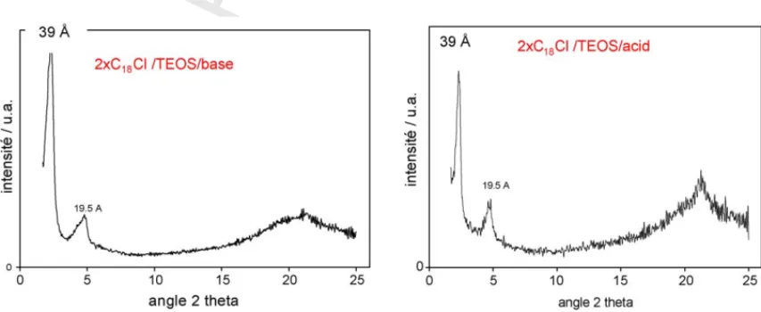
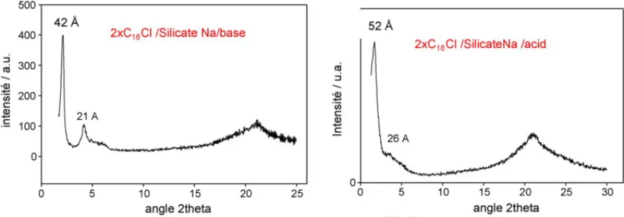
Silica phases precipitated from TEOS precursor are charac- 116
terized by a stacking periodicity of 39 ˚A (Fig. 1), versus 42–52 ˚A 117
for silica obtained from sodium silicate in basic and acidic con- 118
ditions, respectively. However, materials obtained from TEOS 119
have shown a more ordered lattice, richer in silica (Fig. 2). 120
Several parameters were studied in order to increase the thick- 121
ness of the inorganic layers in the TEOS/acidic system: the 122
acid concentration, the molar ratio between silica precursor and 123
template, the hydrolysis or polymerization of the precursor pre- 124
viously to the interaction with the template. However, it is very 125
uneasy to influence the polymerization of the growing silica 126
layer in the direction normal to the inorganic–organic interface: 127
the self-organization of the system occurs by charge–density 128
matching across the interface and there is no driving force 129
towards the incorporation of additional inorganic precursor 130
species when the cationic charges of the surfactant are counter- 131
balanced by a specified quantity of charged silica precursors.7,8 132
After the adjusting of the optimum synthesis conditions, the 133
modification of the lamellar silica was envisaged by the silylat- 134
ing of the constitutive inorganic sheets. The silylating reaction 135
is driven in a solvent allowing the extraction of the template 136
at the same time as the grafting reaction of the silylating agent 137
(trimethylsilyl chloride or TMSCl). Acidic and basic silica were 138
UNCORRECTED PROOF
Fig. 2. XRD patterns of lamellar silica obtained from sodium silicate in basic medium (left) and acidic medium (right).
Fig. 3. Transmission electron micrographs of lamellar silica after silylting by TMSCl in HMDS.
successfully silylated. The extraction of the template, in the
139
case of ionic binding, is possible thanks to the chloride ion
140
released from the trimethylsilyl chloride. All characterization
141
techniques agree to certify that the lamellar organization is
pre-142
served upon silylating, as shown for example by transmission
143
electron microscopy (Fig. 3). Single silica layers can be observed
144
with poor rigidity and extremely high aspect ratio.
145
Quantitative 29Si solid state NMR has been performed on
146
the acidic substrate before and after silylating (Fig. 4). Before
147
surface modification, the intercalated lamellar silica is mainly
148
constituted by Q3and Q4silicon atoms in equivalent quantity.
149
Fig. 4. Repartition of Si atoms types before and after silylating, calculated from MAS-NMR spectra.
The initial silica network can be considered as thin lamellae 150
with 50% of “inner Si” atoms (Q4) and 50% of “surface Si” 151
(Q3) atoms bearing an OH group. This reveals the very thinness 152
of the layers, which have a very high surface/volume ratio. After 153
the grafting of TMS, an intense peak appears in the spectrum, 154
corresponding to the TMS signal. This new peak counts for 25% 155
of the total spectrum area, while the Q3peak decreases down 156
to 9.5% and the Q4increases up to 65.3%. In the modified sub- 157
strate, there is thus 6.8 times more Q4atoms than Q3. It can be 158
calculated that 3/4 of the surface SiOH groups have fixed a TMS 159
molecule, which is a large proportion regarding the size of the 160
TMS group.9 161
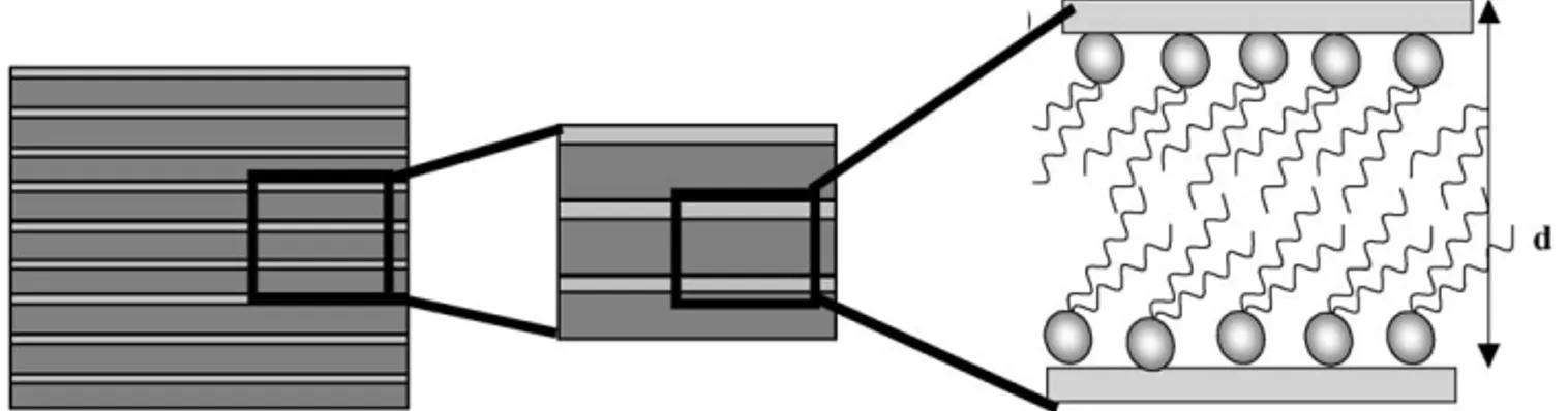
In order to propose a comprehensive description of the inner 162
structure of the lamellar silica’s, poorly described in the litera- 163
ture, we built a representative model of the inorganic–organic 164
stacking, which consists in thin silica sheets intercalated by dou- 165
ble layers of quaternary alkylammonium molecules (Fig. 5). The 166
complete model describes the molecular configuration of the sur- 167
factant in the interlayer space, its anchoring mechanism at the 168
silica surface, the molecular organization of the silica network, 169
the lamella thickness, the surface silanol packing density and an 170
estimation of the electrical residual charge. This will be partly 171
described hereafter. Surfactant bearing two long alkyl chains 172
are known to adopt a tilted bilayer configuration, close to the 173
crystal structure of the pure surfactant salt, when intercalated in 174
UNCORRECTED PROOF
Fig. 5. Schematic representation of the lamellar organization of the as-sysnthesized mesostructured lamellar silica phases. Surfactant counter-ions, if present, are not explicitly shown for clarity.
Fig. 6. Proposed structure of the lamellar silica phase after silylating. Light grey tetrahedra constitute SiO2layers with tridymite crystal structure, dark grey tetrahedra
represent the grafted TMS groups.
Table 1
Comparison of the structural characteristics of lamellar silica’s obtained in acidic and basic conditions Silica precursor Synthesis pH of the substrate (before silylating) dmaxof as-synthesized substrate ( ˚A) dmaxof substrate modified by TMSCl ( ˚A) TMS fixed amount (wt.%) SiO2content (dry residue at 1000◦C) (wt.%) Estimated layer thickness ( ˚A) TEOS 0 37.6 20.5 3.5 88.3 11.3 Na silicate 12 41.5 17.0 4.0 71.4 7.8
Behavior under silylating treatment by TMSCl and estimated silica layer thickness.
a more disordered configuration, closer to the liquid state, but
176
with a similar thickness of the organic bilayer.10
177
The proposed structure, based on experimental observations,
178
is represented in Fig. 6. The silica layers are very thin and
179
the constitutive Si–O tetrahedra are arranged in a tridymite-like
180
structure,11 with pointing-out silanols groups on both sides of
181
the sheet. However, this structure must be disordered since the
182
silica appears amorphous in the XRD patterns. Both sides are
183
covered with a molecular layer of trimethylsilyl (TMS) groups,
184
represented as dark grey tetrahedra, with a tilt angle of 149◦,
185
calculated from hexamethyldisiloxane Si–O–Si angle.12
Crys-186
tal structure models allow to measure the thickness of such a
187
TMS layer, which is estimated to be 4.6 ˚A.
188
Combining thermogravimetric determination of the TMS
189
content, which appears similar for both acidic and basic
sub-190
strates, and stacking periodicity obtained from XRD patterns, it 191
is possible to give an estimation of the silica sheet layer thick- 192
ness (Table 1). The thickness is evaluated by subtracting two 193
TMS layers thickness from the dmaxof the silylated material. 194
This confirms the extremely small value of the silica layer thick- 195
ness, and shows that TEOS-based materials are actually made of 196
thicker silica sheets than sodium silicate-based materials, with 197
a difference on the order of 3.5 ˚A.13 198
4. Conclusions 199
We have studied a wide variety of inorganic phases 200
with lamellar structure, from the synthesis to their complete 201
UNCORRECTED PROOF
The liquid crystal templating method is a suitable way to
pro-203
duce silica phases with lamellar organization exhibiting good
204
structural properties. The surface modification and elimination
205
of the organic template is a very promising way to develop
sil-206
ica layers with a huge aspect ratio, combined with customized
207
surface functionality.
208
References
209
1. Kresge, C. T., Leonowicz, M. E., Roth, W. J., Vartuli, J. C. and Beck, J.
210
S., Nature (London), 1992, 359, 710.
211
2. Beck, J. S., Vartuli, J. C., Roth, W. J., Leonowicz, M. E., Kresge, C. T.,
212
Schmitt, K. D. et al., J. Am. Chem. Soc., 1992, 114, 10834.
213
3. Mitchell, D. J. and Barry, W. N., J. Chem. Soc. Faraday Trans., 1981,
214
77, 601.
215
4. Kunieda, H. and Shinoda, K., J. Phys. Chem., 1978, 82, 1710.
5. Lin, H. P., Liu, Y. H., Kao, C. P., Liu, S. B. and Mou, C.Y., Studies in 216
surface science and catalysis. In Zeolites and mesoporous materials at 217
the dawn of the 21st century, Vol 135, 2001, pp. 4733–4739. 218
6. Lin, H. P., Yang, L. Y., Mou, C. Y., Liu, S. B. and Lee, H. K., New J. 219
Chem., 2000, 24(5), 253–255. 220
7. Monnier, A., Sch¨uth, F., Huo, Q., Kumar, D., Margolese, D. I., Maxwell, 221
R. S. et al., Science, 1993, 261, 1299. 222
8. Huo, Q., Margolese, D. I., Ciesla, U., Demuth, D. G., Feng, P., Gier, T. 223
E. et al., Chem. Mater., 1994, 6, 1176. 224
9. Wouters, B. H., Chen, T., Dewilde, M. and Grobet, P. J., Micropor. Meso- 225
por. Mater., 2001, 44/45, 453. 226
10. Vaia, R., Teukolski, R. K. and Giannelis, E. P., Chem. Mater., 1994, 6, 227
1017. 228
11. Kihara, K., Z. Kristallogr., 1978, 148, 237. 229
12. Barrow, M., Ebsworth, E. and Harding, M., Acta Crystallogr. Sect. B: 230
Struct. Sci., 1979, B35, 2093. 231
13. Henrist, C., Vogels, C., Rulmont, A. and Cloots, R., New J. Chem., 2005, 232