HAL Id: hal-02123811
https://hal.archives-ouvertes.fr/hal-02123811
Submitted on 9 May 2019HAL is a multi-disciplinary open access archive for the deposit and dissemination of sci-entific research documents, whether they are pub-lished or not. The documents may come from teaching and research institutions in France or
L’archive ouverte pluridisciplinaire HAL, est destinée au dépôt et à la diffusion de documents scientifiques de niveau recherche, publiés ou non, émanant des établissements d’enseignement et de recherche français ou étrangers, des laboratoires
monitored by acoustic emission
Imen Yahyaoui, Marianne Perrin, Xiaojing Gong, Hang Li
To cite this version:
Imen Yahyaoui, Marianne Perrin, Xiaojing Gong, Hang Li. Damage evolution in wood under tensile loading monitored by acoustic emission. SHATIS’17 4th International Conference on Structural Health Assessment of Timber Structures, Sep 2017, Istanbul, Turkey. �hal-02123811�
DAMAGE EVOLUTION IN WOOD UNDER TENSILE LOADING
MONITORED BY ACOUSTIC EMISSION
I.Yahyaoui1, M.Perrin1, X.J. Gong1, H.Li1
1
Institut Clément Ader (ICA), CNRS UMR 5312, University of Toulouse, UPS, 1 rue Lautréamont, 65000 Tarbes, France
Keywords: Wood, Acoustic Emission, Damage evolution, Failure mechanisms Abstract.
Considerable progress can be observed within recent years in timber structures. But, the devel-opment of damage in these structures may cause catastrophic events. Therefore, frequent moni-toring should be conducted to estimate the health condition of these structures. In this context, the acoustic emission (AE) is an efficient method for real time monitoring as well as damage growth in both structural components and laboratory specimens. In this study tensile tests in the axial direction were performed on standardized wood specimens. Three wood species were tested including Douglas fir, silver fir and poplar. Actually, these woods have close density, but their structures and their mechanical behaviors are quite different, so conduce to different damage process. The Douglas fir is softwood with a pronounced distribution of earlywood and latewood, their high strength among softwoods explains their important application for structural purposes. Silver fir is also softwood and it is abundant in the Pyrenean region in France, so interested to study for economical reason. Moreover its structure is quite different from that of Douglas fir. Finally poplar wood is a hardwood and it’s well known as a homogenous wood. This work aims to investigate their damage process with help of AE sensor. During the test loading data were recorded simultaneously with the transient AE signals. And then we try to correlate the AE sources to the damage mechanism in the woods tested. According to results, the following con-clusions can be stated: The AE data recorded from tensile tests indicate clearly that the scenario from damage initiation, accumulation up to final macroscopic failure is quite different from one wood to another one. It depends strongly on their distribution of early and final wood. The forms and the magnitudes of AE activities are directly related to the annual rings structure. It is shown that the wood with abrupt transition from earlywood to latewood are more emissive than wood with gradual transition. Also, acoustic emission monitoring allows the early detection of damage and the establishment of damage scenarios.
1 INTRODUCTION
Due to the increase of ecological awareness, the use of wood in civil engineering structures like timber bridges has been recently raised. Nevertheless, wood is an anisotropic material which is organized in a complex hierarchical structure distributed across multiple spatial scales, from microscopic to macroscopic scale. Hence, a thorough comprehension of the fail-ure evolution in wood structfail-ures is required to avoid critical situations and to maintain safety standards. Until today, there is a lack of information in literature about tracking back the evo-lution of wood fracture zone to its origin. Such research should determine the temporal-spatial occurrence of damage mechanisms and their interactions at different length scales [1].
Regarding this issue, acoustic emission (AE) method should be suitable which is defined as a transient elastic wave generated by the rapid release of energy due to irreversible phenomenon within a material. It is shown that the acoustic emission (AE) method is appropriate for char-acterizing wood fracture process because it is sensitive to damage mechanisms at different length scales [1-3]. This technique provides advantages of early detection of crack initiation [4]. Besides, detailed monitoring of the damage evolution is allowed by the high time resolu-tion of AE technique
This paper analyses the damage process of three softwood species based on acoustic emission signal parameters. Douglas fir (Pseudotsuga Menziesii), silver fir (Abies pectinata) and poplar
(Populus) were tested under tensile loading, the influence of the heterogeneity induced by the
proportion of earlywood and latewood in annual rings on the acoustic emission response has been discussed.
2 EXPERIMENTAL DETAILS
2.1 Materials and specimens
The materials tested under tensile loading in this study are Douglas fir wood, silver fir wood and poplar wood. All of them have close density but different structure. Douglas fir has large well-defined growth rings and a sharp definition between the earlywood and latewood. For silver fir the transition between earlywood and latewood is more gradual. Only narrow bands of thicker latewood cells divide two regions of wide bands of earlywood. Silver fir structure is considered like uniform structure compared to Douglas fir structure. Poplar wood has different features compared to the two tested softwoods. Notable features for poplar wood are the diffuse pores in no specific arrangement, marginal parenchyma and nodded rays. The transition between earlywood and latewood is not distinct with naked eye so it is why poplar is considered as a homogenous wood.
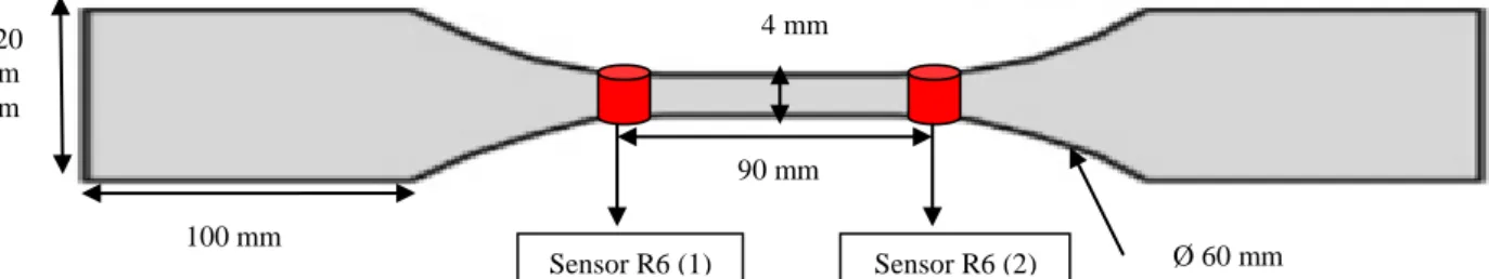
Tensile specimens with dog-bone shape have been prepared from the three species of wood with nominal dimensions according to NF B51-017 (350 mm overall length, 100 mm length, 20 mm width and 20 mm thickness in grip section, 90 mm length, 20 mm width and 4 mm thickness in the calibrated section (Figure 1). All specimens have the length in longitudinal direction and the width in radial direction. To prevent crushing on the specimen by the grips, four tabs in steel of length 60 mm were glued to the ends of the specimen using bicomponent epoxy resin (ESK-48).
Figure 1: Tensile specimen and sensors position
2.2 Test conditions
Five specimens were tested for each wood species. The total number was 5x3= 15 samples. They were conditioned and stored at 20°C and 65% relative humidity before testing. Tensile tests were performed by using universal test machine MTS© 20M with a load cell calibrated in the load range of 100kN. In all tests, load was applied parallel to the grain of wood sample and under displacement control with a constant cross-head speed 2.5mm/min until the speci-men failed. Strain gauges are used to measure the strain along the longitudinal and the trans-versal axis for the purpose to determine Young’s modulus and Poisson’s coefficient of the materials.
2.3 Acoustic emission equipments
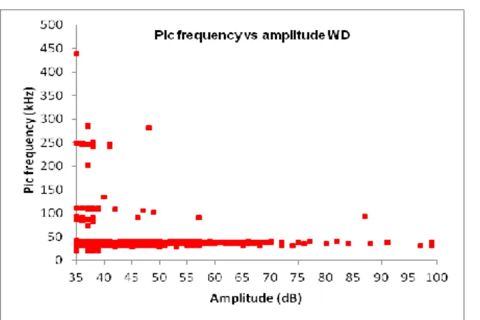
Wood is a very heterogeneous and a highly attenuative material. For these reasons, a pre-liminary study was done to select the suitable sensors for wood materials. In the literature the sensors used for monitoring damage in wood have resonant frequencies between 150 and 300 kHz [1-5]. But a recent study [2] indicated that in the cases of wood fracture process the max-imum Power Spectral Density (PSD) defined as the distribution of energy over the frequency, resided in a low frequency area around 60 kHz. So in order to properly assess the frequency portion of the signal, resonant frequency of the sensor should be carefully taken into account. In this context, four types of piezoelectric sensors were tested in order to select the suitable one: three resonant sensors R15α, R6α and R3α with resonant frequency respectively 150 kHz, 60 kHz and 30 kHz, and one wideband sensor (WD) (frequency band-width between 100 kHz and 1 MHz) are tested. Results of wideband sensor showed that the frequency of damage in wood is situated between 30 kHz and 50 kHz (Figure 2). Consequently, R3α and R6α sensors are the most convenient for wood damage monitoring. In this research work, both of R3α and R6α sensors were used simultaneously. After analyses of the signals recorded by these sen-sors, it is found that the R6α sensors gives better results concerning localization of the events. Therefore we will limit our analyses on the results recorded by R6α sensor in the next parts of this paper. Ø 60 mm 90 mm 100 mm 20 m m 4 mm Sensor R6 (2) Sensor R6 (1)
Figure 2: Pic frequency vs amplitude of WD sensor showing the concentration of hits in a frequency range
be-tween 30 kHz and 50 kHz.
Figure 1 schematizes also the positions of AE sensors on the tested specimen. In order to locate AE events, two R6α sensors were placed on the front side of the tensile specimen one on the top and another on the bottom of the calibrated section. Sensors were fixed with clamps. In order to avoid any loss of acoustic signal at the transducer-sample interface, silicone-free vacuum grease was used to couple the sensors to the surface of specimens. The AE data are recorded with help of an Euro Physical Acoustics system composed by a PCI8 board. The ac-quisition is computed by using AEwin/SAMOS software. The analog filter frequency is set up between 20 and 400 kHz and the acquired signals are preamplified by 40 dB. The environ-mental noise was filtered using a threshold of 35 dB. The timing parameters, peak definition time (PDT), hit definition time (HDT) and hit lockout time (HLT) are set at 40, 200 and 300 μs, respectively [6].These parameters are verified by Pencil-lead breaks (Hsu-Nielsen source) [7] before the beginning of tests. The same sources are used to calculate the wave velocities. These latter are given in table 1. Wave velocity is species dependent. In fact, it increases with the increasing of raw density of the material [8].
Table 1: Wave velocities and raw density of wood species
Wood species Wave velocities (m/s) Raw density (Kg/m 3) Douglas fir 4747 ± 560 501 ± 22.25 Silver fir 4549 ± 164 446 ± 45.43 Poplar 4345 ± 115 410 ± 11.35
3 RESULTS AND DISCUSSIONS
3.1 Mechanical properties from stress stress-strain graph
The fracture stress and the modulus of elasticity for the three woods determined from the tensile tests are shown in Figure 3. It is shown that the tensile strength of Douglas fir is 65% greater than that of silver fir, and 8% greater than that of popular, respectively. These results are compared with those obtained in reference [9] (Figure 3). Good correlation can be pro-nounced for Douglas fir, but not for silver fir and popular wood. The failure stress for three woods in reference [9] seems following the same variation of their density. But it is not really the case regarding the measurement on the woods tested in our study. Concerning the Young’s modulus, it seems density dependent (Figure 3) since Douglas fir is stiffer than the
two other species. Furthermore, silver fir and poplar fir have equivalent stiffness and close densities (Table 1).
Figure 3: Mechanical properties for the three tested wood species
3.2 Failure scenario and damage indication by AE
3.2.1 Douglas fir
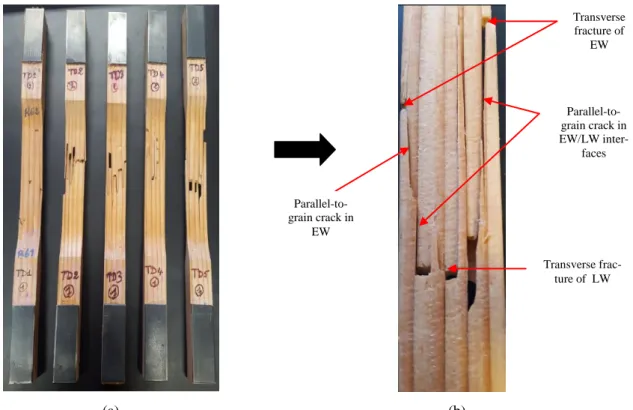
The examination of fracture surface of Douglas fir specimens reveals different damage mechanisms: transverse fracture in earlywood (EW) tracheid, transverse fracture in latewood tracheid (LW) and the parallel-to-grain crack propagation along the EW/LW interfaces and in the EW (Figure 4 a-b).
(a) (b)
Figure 4: (a) Failure patterns observed for Douglas fir specimens (b) Failure modes in TD5 fracture surface
As an example we will focus on TD5 specimen to correlate the AE data with damage mecha-nisms. Figure 5 shows the evolution of the load and of AE parameters in term of cumulative
Transverse fracture of EW Parallel-to-grain crack in EW/LW inter-faces Transverse frac-ture of LW Parallel-to-grain crack in EW
AE hits as a function of the testing time. In general, the load/time curve could be decomposed in three stages based on cumulative AE hits. In the linear deformation part, some emissions have been observed. In their study [10] suggested that the random AE signals observed in the elastic deformation stage are the result of the non uniform stress field resulting from non-homogeneity of wood structure. Actually, reorientations in wood structure are observed, which lead to adaptation for new conditions of loading [10]. When it entered into the non-linear deformation part (part II), the rate of cumulated AE hits increased. This rapid increase could be attributed to inter-laminar shear in planes of weakness like earlywood/latewood in-terfaces [8]. In this stage parallel-to grain micro-cracks in EW/LW transition zones are devel-oped. Then, the specimen entered to the fracture stage (part III) which leads to a sharp increase in cumulative AE hit. As damage in the specimen intensified, macro-cracking took place and the first visible crack was found at t= 64.3s, herein a sharp drop of the load can be observed (Figure 5- Point B). A transverse crack in the EW appeared, and then the crack propagated longitudinally in the EW/LW interfaces. Successively, a second, a third visible crack across EW occurred at t= 68.2s and at t=69.47s, respectively (Figure 5 – Point C and Point D), they are accompanied by the longitudinal crack growth or in EW tracheid, or at the EW/LW interface. Thereafter, the rate of cumulated AE hits increased as the damage contin-ued to progress until the fourth and final fracture at t=78.1 s (Figure 5- Point E). The several drops of load indicate that the specimen still had high load-bearing capacity after the first vis-ible fracture [11]. A B C D E I II III A B C D E
Even though the damage process for each Douglas specimen could not be exactly the same, a typical damage process in Douglas specimen can be proposed. Under tensile loading, the dif-ferent stiffness between earlywood (EW) and latewood (LW) generates a shear stress at the EW/LW interfaces, which is the weakest layer because the density of wood between EW and LW changes abruptly [12]. Micro-cracks should initiate or at EW/LW interfaces or in EW, where the strength is much lower than that in LW. Their growth and coalescence conduce to longitudinal crack propagation. This process is sometimes accompanied by the fibre breaking in EW [13]. The transverse fracture in EW generates a tensile/flexion coupling effect, which accentuates even more the fibre breaking in EW. When the crack growth attains EW/LW in-terfaces levels, under shear stress (mode II) and peel stress (mode I), the longitudinal crack propagation (parallel-to-grain) along EW/LW interfaces will occur. And then, one of the latewood layers breaks, the rest of specimen cannot support the higher load and final fracture occurs [13]. On fracture surfaces, the longitudinal crack growth in EW and at EW/LW inter-faces was evident, and the fiber breaking in EW is so shown stair-shaped.
3.2.2 Silver fir
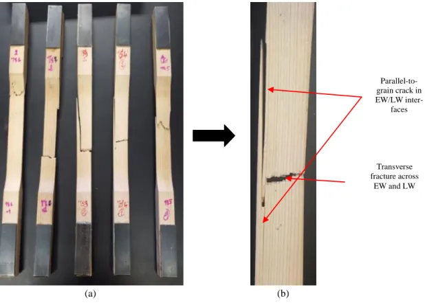
Silver fir specimens under tensile loading failed usually in brittle manner (Figure 6). Much less crack propagation parallel-to-grain direction were observed along EW/LW interfaces or/and in the EW. The fracture surfaces appear more flat and demonstrate simultaneous trans-verse fracture in earlywood tracheid and in latewood tracheid.
The representative specimen TS4 (Figure 6-b) displays transverse crack that extend entirely through the sample width across the EW and the LW. Some longitudinal crack propagations have been also seen along EW/LW interfaces.
(a) (b)
Figure 6: (a) Failure patterns observed for silver fir specimens (b) Failure modes in TS4 specimen
Transverse fracture across EW and LW Parallel-to-grain crack in EW/LW inter-faces
Figure 7 shows the evolution of the load and of cumulative AE hits as a function of the testing time for the specimen TS4. Under low load (Part I), silver fir generated few emissions. In the second part (Part II), the cumulative AE hits increased with the load rise. Emissions in this stage can be attributed to micro-cracking in cells of earlywood since the structure of wood with narrow rings consists principally of earlywood tracheid [14]. The brittle fracture across EW starts with a significant increase in the rate of cumulated AE hits (Part III). When the EW is sufficiently damaged, the LW can no longer withstand the applied loads, the final fracture occurred. Actually the latewood has to be more resistant as in silver fir as the walls of late-wood cells are much thicker than those of earlylate-wood cells. Moreover at the last part of the test, the tensile/flexion coupling due to the transverse crack promotes the longitudinal crack prop-agation at EW/LW interface.
Figure 7: Force vs time, cumulative hits vs time and damage scenario of TS4 specimen
In conclusion, silver fir has narrow growth rings, the specimens under tensile loading failed usually in brittle manner. The micro-cracking initiates firstly in the EW, the development of the micro-cracks leads to fiber breaking in the EW. When there are enough fibers broken in the EW, the transverse fracture in the LW occurs. The transverse crack across the section pro-duces a tensile/flexion coupling effect, which promotes the longitudinal crack propagation at EW/LW interfaces, under mode I due to peel stress and mode II due to shear stress.
A B
I II III B
3.2.3 Poplar
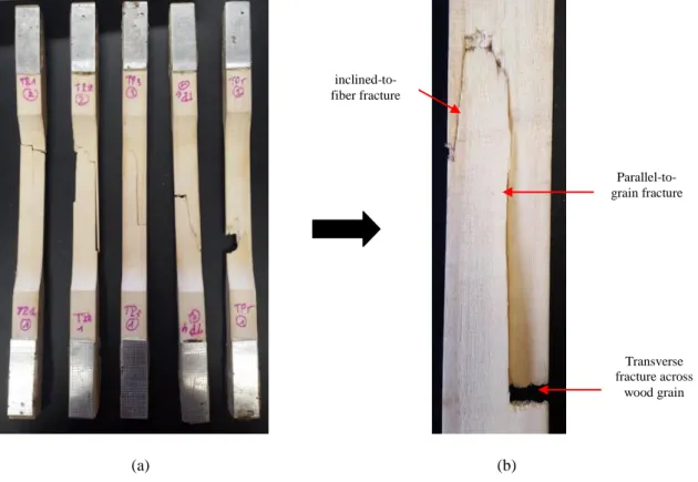
Poplar is a hardwood and considered as quasi homogeneous material, because no transition from earlywood (EW) and latewood (LW) can be distinguished. The specimens shown in Figure 8-a display combination of tension and shear fracture, because the fracture surface of all specimens runs partially across wood grain and partially inclined to the grain direction. The specimens TP3 and TP4 display a large part of the shear fracture where the fracture sur-face is inclined to the fibers. Moreover, more or less longitudinal macro-cracking was also observed in the specimens.
(a) (b)
Figure 8: Failure patterns observed for poplar specimens (b) Failure modes in TP3 specimen
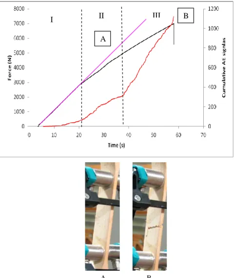
For the representative specimen TP3 (Figure 8-b), the analysis of the AE cumulative hits dur-ing tensile test allows to divide the damage process in three parts (Figure 9). Part I is charac-terized by an absence of detectable acoustic emission. Poplar specimen (TP3) starts to generate acoustic signals at t=22.43s in part II. Then, the cumulative AE hit increased slightly with the load increase. At this stage the signals can come from the initiation and development of micro-cracking across wood cells since they are considered as the main spot of mechanical weakness in bulk wood specimens. The early stage in part III is characterized by a remarkable increase in cumulative AE hits, herein the damage mechanisms could be the growth of micro-cracks and the arrest of crack propagation at a vessel level, a mechanism specific to hardwood. At final fracture of the specimen, the load drops sharply and the cumulative AE hits suddenly rises when the visible cracks appeared at t=84.32s (Figure 9-Point B). Acoustic emission ac-tivity in this stage is mainly attributed to fiber breakage. Actually, in the final fracture process, under the effect of the stress concentration around the micro-cracks, the fibers of the wood could be broken, forming cross-grain macro-cracks. In the same time the growth and the coa-lescence of theses micro-cracks could also follow the direction parallel-to-grain due to the shear stress induced by wood structure at fiber/fiber interfaces. When a cross-grain crack
Transverse fracture across wood grain Parallel-to-grain fracture inclined-to-fiber fracture
meets a parallel-to-grain crack, their coalescence results in a crack inclined to the grain direc-tion.
Figure 9: Force vs time, cumulative hits vs time and damage scenario of TP3 specimen
Consequently, the damage scenario of the tested poplar wood under tensile loading could be supposed as following: the damage process is started by micro-cracking in the wood cells. The growth of micro-cracks can be stopped at a vessel due to hardwood structure. Final frac-ture of the specimen occurs in a brittle manner. When a packet of fibers are broken simultane-ously, instable crack propagation can be observed across-to-grain, parallel-to-grain as well as in the direction inclined to wood grain.
3.3 Comparison AE responses for species tested
The three wood species studied here show in general three stages of AE activity during tensile loading. But the total cumulative hits are quite different between species. Douglas fir generates higher total AE signals: more than twice of cumulated AE signals of silver fir and nine times more than cumulated AE signals of poplar (Figure 10). This investigation agrees well with the findings in reference [4], which indicated that the higher is the contrast between early and latewood in annual ring, the higher AE cumulative counts should be expected dur-ing tensile parallel to grain loaddur-ing. Moreover the important difference in AE responses
be-B A I II III B A
the higher energy consumed when the crack propagate in softwood [15]. Furthermore, hard-wood requires a high stress levels for macro-crack initiation and its structure holds crack ar-rest components. In fact, vessels in hardwood species can stop the crack propagation [16]: the crack tends to open the vessel or deviates around the vessel and then stooped (Figure 11). De-spite the crack arrest, the crack propagates in brittle manner in hardwood species [15]. These reasons explain why the poplar wood remained silent in early stage of loading and released less emission hits until the final fracture. Furthermore, wood structure contains radially ori-ented parenchyma called rays. They provide a mechanically strong structure which inhibits the crack propagation [17-18]. In fact, the volumetric proportion and the size of rays are dif-ferent between soft and hardwood. The conifers wood contains around 5-10% of rays while it is around 10-32% in hardwood [19]. Therefore, the rays could strengthen poplar wood to crack growths more than the two softwoods (Douglas fir and silver fir) which explains the small AE signals generated during poplar damage.
Figure 10: Cumulated AE signals of tested wood species
Figure 11: Crack arrest at a vessel [16]
4 CONCLUSIONS
In this study, the evolution of damage of three wood species under tensile loading was monitored by AE. The following conclusions can be stated:
- The magnitudes of AE activities as a function of time are directly related not only to the annual rings structure, but also to micro and meso-structures of woods. It is shown that the wood with well-defined growth rings is more emissive than wood with narrow rings and wood with homogeneous structure. The responses of AE are quite different between soft-wood and hardsoft-wood. More cumulative hits have been obtained during damage process in softwood than those in hardwood.
- AE is a promising technique for monitoring the health of timber structures and for detect-ing the onset of micro and macro crackdetect-ing. In fact, the AE data of tensile tests on three different wood species indicate clearly different scenarios from damage initiation and ac-cumulation up to final macroscopic failure. Therefore, it is possible to associate AE re-sponses to the damage mechanisms and the damage level in wood structures, so as to predict service life or/and service safety for a timber structure.
- Actually, different parameters, such as forms and the energy of AE activities are worthy to study in future works in order to correlate different damage mechanisms to AE events.
REFERENCES
[1] Ritschel, F., Brunner, J. A. and Niemz, P. 2013. “Nondestructive evolution of damage accumulation in tensile test specimens made from solid wood and layered wood materials”. J.
composite structures, 95, Pp: 44-52.
[2] Varner, D. 2012. “Acoustic emission during static bending of wood specimens”. PhD
the-sis. Mendel University in Brno.
[3] Wu, Y., Shao, ZP. and Wang, F. 2014. “Acoustic emission characteristics and felicity ef-fect of wood fracture perpendicular to the grain”. J. of tropical forest science, 26 (4), Pp: 522-531.
[4] Ansell, MP. 1982. “Acoustic emission from softwoods in tension”. Wood Sci. technol, 16, Pp: 35-58.
[5] Vautrin, A. 1987. “Acoustic emission characterization of flexural loading damage in wood”. J. of materials science, 22, Pp: 3707-3717.
[6] Lamy, F., Takarli, M., Angellier, N. and Dubois, F. 2015. “Acoustic emission technique for fracture analysis in wood materials”. Int. J. Fract, 190.
[7] Nilson, A. 1980. “Acoustic emission source based on pencil lead breaking”.
Svejsecntralen, 80.
[8] Bucur, V.2006. “Acoustics of wood”, Springer Series in Wood Science. Second Edition Germany.
[9] Hearmon, R.F.S. 1948. “The elasticity of wood and plywood”. Dept. Sci. Ind. Res. For.
Prod. Res. Spec. Report No 7, HMSO, London.
[10] Raczkowski, J. and Molinski, W. 1994. “Acoustic emission in fracture machanics of wood”. J. of theoretical and applied mechanics, 2 (32).
[11] Liew, W.Y.H, Yeo, K.B and Ben Ismail, M.A. 2011. “Fracture behavior of tropical hardwood under tensile load”. Int. Conference on advanced Science engineering and
infor-mation technology, Malaysia 14-15 January 2011.
[12] Kollmann, F.P. and Coté, W.A. 1968. “Principles of wood science and technology I: sol-id wood”, Springer-Verlag New York Inc.
[13] Sipolla,M. and Fruhmann,K.2001. “In situ longitudinal tensile tests of pine wood in ESEM”. Holzforshung, 56:669-675.
[14] Johnson, P.P.A and Brundage, M.R. 1934. “Properties of white fir and their relation to the manufacture and uses of the wood”. Technical Bulletin No. 408, Unites States Departement of Agriculture, Washington, D, C.
[15] Reiterer, M.F.Stanzl-Tschegg, SE. and Tschegg, E.K. 2000. “Mode I fracture and acous-tic emission of softwood and hardwood”. Wood Science and Technology, 34, Pp: 417-430. [16] Ashby, A. and Gibson, L.J. 1988. “Cellular solids: Structure and properties”. Pergamon Press, New York, NY.
[17] Reiterer, A., Burgert, I., Sinn, G. and Tschegg, S.E. 2002b. “The radial reinforcement of the wood structure and its implication on mechanical and fracture mechanical properties-a comparison between two tree species”. J. Mater. Sci. 37, Pp: 935 – 940.
[18] Bordner, J., Schlag, M.G. and Grull, G. 1997. “Fracture initiation and progress in wood specimens stressed in tension: Part I: clear wood specimens stressed parallel to the grain”.
Holzforshung. 51, Pp: 479-484.
[19] Ozden, S., Ennos, A.R. and Cattaneo, M.E.G.V. 2016. “Transverse fracture properties of green wood and the anatomy of six temperate tree species” Forestry (Lond). 90