HAL Id: lirmm-01276796
https://hal-lirmm.ccsd.cnrs.fr/lirmm-01276796
Submitted on 20 Feb 2016
HAL is a multi-disciplinary open access archive for the deposit and dissemination of sci-entific research documents, whether they are pub-lished or not. The documents may come from teaching and research institutions in France or
L’archive ouverte pluridisciplinaire HAL, est destinée au dépôt et à la diffusion de documents scientifiques de niveau recherche, publiés ou non, émanant des établissements d’enseignement et de recherche français ou étrangers, des laboratoires
Software Architecture Constraint Reuse-by-Composition
Chouki Tibermacine, Salah Sadou, Tu Minh Ton That, Christophe Dony
To cite this version:
Chouki Tibermacine, Salah Sadou, Tu Minh Ton That, Christophe Dony. Software Architecture Constraint Reuse-by-Composition. Future Generation Computer Systems, Elsevier, 2016, 61, pp.37-53. �10.1016/j.future.2016.02.006�. �lirmm-01276796�
Software Architecture Constraint Reuse-by-Composition
Chouki Tibermacinea, Salah Sadoub, Minh Tu Ton Thatb, Christophe Donya
aLIRMM, CNRS and Montpellier University, France bIRISA, University of South Brittany, France
Abstract
Architecture constraints are specifications which enable developers to for-malize design rules that architectures should respect, like the topological conditions of a given architecture pattern or style. These constraints can serve as a documentation to better understand an existing architecture de-scription, or can serve as invariants that can be checked after the application of an architecture change to see whether design rules still hold. Like any spec-ifications, architecture constraints are frequently subject to reuse. Besides, these constraints are specified and checked during architecture design time, when component descriptions are specified (or selected from repositories), then instantiated and connected together to define architecture descriptions. These two facts (being subject to reuse and instantiation/connection) make architecture constraints good candidates for component-based design within a unified environment. In this paper, we propose a component model for specifying architecture constraints. This model has been implemented as an extension to an ADL that we have developed, which is called CLACS. The obtained process advocates the idea of specifying architecture constraints us-ing the same paradigm (of component-based development) as for architecture description. To evaluate the component model, we conducted an experiment with a catalog of constraints formalizing the topological conditions of ar-chitecture patterns. The results of this experiment showed that constraint specification is improved by this reuse-by-composition model.
Keywords: Architecture Constraint, Software Component, Architecture Description, OCL
Email addresses: [email protected] (Chouki Tibermacine),
[email protected] (Salah Sadou), [email protected] (Minh Tu Ton That), [email protected] (Christophe Dony)
1. Introduction: Context and Motivations
Software architectures are key design artifacts, which are sketched at the beginning of the development process and maintained throughout the soft-ware life-cycle in order to satisfy and make persistent user (functional) and quality requirements. These design artifacts play several roles in software development. First, they provide a global view of the structure and/or be-havior of the developed software system, hiding some implementation details, for enabling an easy global comprehension of the software system. Second, they make easier the reasoning about non-functional requirement satisfac-tion, by providing a good means for capturing and documenting a part of the initial design choices. Third, they represent an interesting media for com-municating with the other stakeholders involved in the software development project.
Architecture constraints represent a formal description of conditions im-posed by some design choices made in an architecture description [1, 2, 3]. By formal description, we mean here a processable (checkable) specification of these conditions. Examples of such constraints include the topological conditions imposed by an architecture style or pattern used when designing a software architecture. The benefit from these constraints is twofold. First, they play a documentation role and thus help developers in understanding an architecture description and the design choices made during its construc-tion. For example, a system designed using a given set of patterns, like the Facade and the Composite [4] can be documented using constraints, stating for instance for the Facade pattern that there must be a unique interface for client components. This documentation can be read by future develop-ers, involved in the system’s maintenance, to know without ambiguity which patterns have been instantiated in the architecture. This helps them in bet-ter understanding the previous design choices. Second, they play the role of invariants that can be checked after an architecture evolution [5]. If devel-opers decide to make some changes to the evolved system’s architecture, the checking of constraints enables to notify the developers about the instanti-ated patterns potentially affected by changes (if for example the interface of the Facade is anymore the only interface to client components).
In contrast to constraints in constraint programming, architecture con-straints are not conditions that should be satisfied by a solution in an
op-timization problem, where we would like to find an optimal solution among many possible ones. They are conditions that are evaluated to see whether a given single “fixed” solution (our architecture description) satisfies the con-ditions or not. If the concon-ditions are not satisfied, we are not led to find another possible solution. We should in this case change the current so-lution (architecture description), by undoing previous changes for example, and then re-evaluate the conditions. Furthermore, conditions in architecture constraints should not be confused with invariants in contract programming (or Design by Contract [6]). In contract programming, invariants are mainly checked at runtime, while conditions in architecture constraints are checked statically. In architecture constraints, we analyze the architecture descrip-tion of a software system, and not the dynamic states of components in this architecture, as done in contract programming.
The context of our work is component-based software development (CBSD). In a CBSD setting, architecture descriptions are specified using component-based Architecture Description Languages (ADLs). Some ADLs provide means to specify architecture constraints (see [3] for a literature review). Un-fortunately these languages provide limited solutions for reusing constraints, while these are by nature reusable specifications (examples in the following sections and the results of the experiment –Section 6– confirm these state-ments). For defining new constraints, developers should be able to reuse existing constraints and combine them with others (possibly new ones).
In a previous work [7], we proposed a family of languages based on OCL (Object Constraint Language [8]), for specifying architecture constraints. These languages offer the possibility for architects to easily specify constraints depending on the language used to define their architecture descriptions. These languages benefit from the expressive power and ease of use [9] of their underlying language, OCL. However, like existing ADLs or constraint languages, this family of languages does not provide means for efficiently reusing constraints.
To make such specifications reusable, we can imagine a solution where constraints are wrapped in functions, as in procedural programming. These functions embed thus the checking of constraints. Then, these functions, which can be organized in modules, can be imported and called: i) in ar-chitecture descriptions whenever constraints must be checked, or ii) in spec-ifications of other (more complex) constraints. In this paper, we pushed further this reuse schema (of wrapping constraints in functions) and we pro-pose that architects, who define architecture descriptions using a component
model [10], specify architecture constraints using the same component model. In this way, constraints are specified in component descriptors, which can be instantiated and connected to other components. The ultimate goal here is to provide a unified environment for architecture description.
This article is an extended version of a previous communication [11]. In this article, we have more particularly:
• detailed and extended our specification of the model,
• illustrated our model with several (different, including real-world) ex-amples,
• largely extended the related work,
• provided another more practical implementation (as a UML profile) • and added an empirical evaluation established through the construction
of a catalog of constraint components for architectural patterns. In the following section, we illustrate through examples the problem ad-dressed in our work and present the motivations of the proposed model. In Section 3, we first give an overview of the approach that we propose, then we detail our model for specifying software architecture constraints in com-ponents. In Section 4, we show through examples how our approach can be used in practice. After that, we introduce in Section 5 the current imple-mentation of the proposed approach integrated to a component-based ADL, called CLACS. In Section 6 we expose an empirical evaluation of this model where we quantified the reusability provided by the component model. This evaluation has been performed on a set of architecture constraints formaliz-ing the topological conditions of 31 architectural patterns. Before concludformaliz-ing and listing the perspectives of this work in the last section, we discuss the related work in section 7.
2. Context and Problem Statement
The constraints shown in this section are defined in ACL (Architecture Constraint Language [7]), which is a language based on the OMG’s Object Constraint Language (OCL). Besides, architecture descriptions to which con-straints are associated are defined using UML. First, we introduce ACL and the UMLs metamodel for component-based architecture description. Then,
we present two examples of ACL constraints. At last, we make a summary of the problems identified on these examples.
2.1. Introduction to ACL and UML’s Component Model
Constraints in ACL are defined as invariants. They navigate in the meta-model representing the abstract grammar of the ADL used for describing the architectures on which the constraints apply1. In contrast to OCL (when
used at the metamodel level), they do not apply to all instances of this metamodel, i.e. all architecture descriptions defined using that ADL. They however apply only to a specific instance of this metamodel, which is an ar-chitecture description referenced in the context part of the constraint. The use of this metamodel provides the architects with the capability of defining (in the constraints) expressions that analyze architecture descriptions.
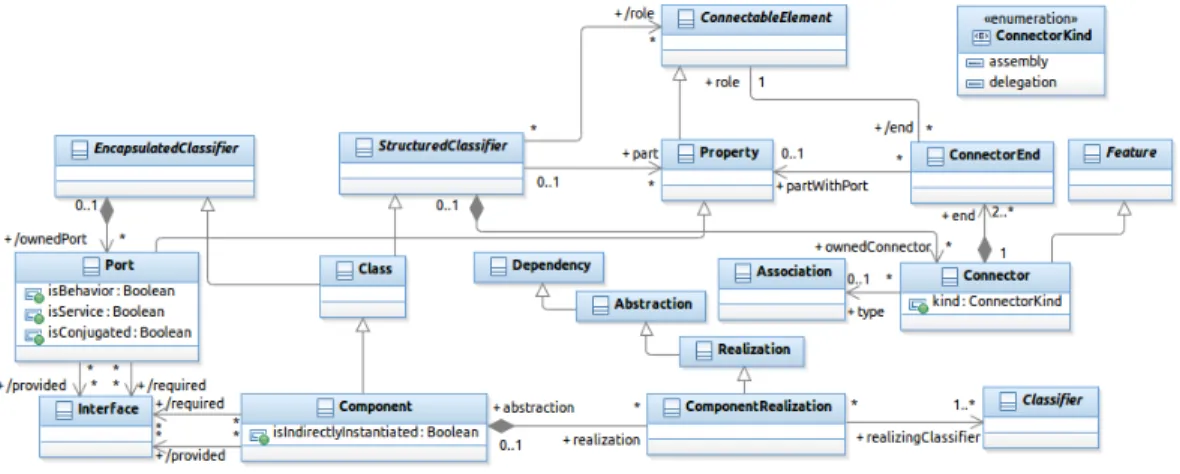
Figure 1: An Excerpt from the UML 2.x metamodel (Components and Composite Struc-tures)
The examples of architecture constraints presented in this section nav-igate in the metamodel shown in Figure 1, which is an excerpt from the UML 2.x metamodel. This metamodel encompasses the definition of UML components and composite structures [12]. The meta-class Component is a
1By “navigate in the metamodel”, we mean that we use, in the constraints, OCL
navigation expressions in which we move from one meta-class to another one in order to analyze the architecture elements which are instances of these meta-classes.
specialization of Class. This gives to components class capabilities (par-ticipating in generatization relations, or playing the role of classifiers for instances, for example). In addition, Class inherits in this model from EncapsulatedClassifier and StructuredClassifier. This means that a component (as a specialization of EncapsulatedClassifier) can have ports that can declare provided and/or required interfaces (see the bottom left part of Figure1). This enables components to encapsulate their contents, and ex-pose their functionnality via their ports, which are the communication points with their environment (other components). A component (as a specializa-tion of StructuredClassifier) can declare parts, which are a specific kind of properties that reference the instances that compose the internal structure of the component (we refer to this as the composite structure). These parts can play roles in connections (they can be attached to connector ends). A com-ponent can have connectors which link connectable elements. Such elements can be ports of a part in a composite structure of a component (Association between ConnectorEnd and Property in the metamodel) or ports of the en-compassing component having a composite structure. Finally, a component can have one or several Classifiers (classes, for example) which realize it. By Realization of a component, the UML specification refers to the set of classifiers that implement the behavior of the component. These classifiers can be other components (Component is a specialization of Classifier).
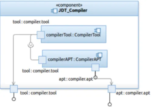
Figure 2: An Example of a UML 2.x diagram
An example of a UML 2 diagram is depicted in Figure 2. (This is an excerpt from Figure 11presented in Section4.3.) JDT Compiler is a compo-nent. compilerTool and compilerAPT are parts in the composite structure of this component. tool and apt in the bottom of the figure are ports of the component, with two different provided interfaces. Besides, a required
interface is declared in the tool port of compilerAPT part. There are three connectors in this example: two delegation connectors defined between the parts and their encompassing component, and an assembly connector which links the required interface and the provided one of the two parts.
2.2. Illustrative Examples
The first constraint presented below checks if the architecture description of a component named ACS (Access Control System) conforms to the layered architecture style [13]. In this constraint we assume that the internal ar-chitecture of this component contains a set of component instances each of which representing a layer.
1 context ACS : Component inv L a y e r e d A r c h i t e c t u r e :
2 l e t l a y e r s : Set ( Component ) = ACS . p a r t . type−>a s S e t ( )
3 −> s e l e c t ( t : Type | t . o c l I s K i n d O f ( Component ) )
4 −> c o l l e c t ( t : Type | t . oclAsType ( Component ) ) ,
5 c o n n e c t o r s : Set ( C o n n e c t o r ) = ACS . ownedConnector
6 −> r e j e c t ( c : Connector | c . k i n d=ConnectorKind : : d e l e g a t i o n )
7 i n
8 −− Each l a y e r s h o u l d be c o n n e c t e d 9 l a y e r s −>f o r A l l ( c : Component |
10 c o n n e c t o r s . end . r o l e −>i n c l u d e s ( c . ownedPort ) )
11 and
12 −− Each l a y e r s h o u l d be c o n n e c t e d t o a t most 13 −− two o t h e r l a y e r s
14 l a y e r s −>f o r A l l ( com : Component |
15 c o n n e c t o r s −>s e l e c t ( con : C o n n e c t o r |
16 con . end . r o l e −>i n c l u d e s ( com . ownedPort ) )
17 −> s i z e ( ) <= 2 ) 18 and 19 −− The number o f l a y e r s t h a t a r e c o n n e c t e d 20 −− t o o n l y one o t h e r l a y e r i s e q u a l t o two 21 −− ( t o p and bottom l a y e r s ) 22 l a y e r s −>s e l e c t ( c : Component | 23 c o n n e c t o r s −>one ( con : C o n n e c t o r |
24 con . end . r o l e −>i n c l u d e s ( c . ownedPort ) ) )−> s i z e ( ) = 2 Listing 1: ACL Constraint for a Layered Architecture
We assume in this example that the architecture description should con-tain at least three layers. We obviously suppose here that the layered ar-chitecture style cannot be checked on an arar-chitecture description having an internal architecture with only two component instances.
This constraint checks first if all the layers are connected, by analyzing all the connectors that are attached to the ports of the layers (we exclude delegation connectors between ACS and its internal components in Line 6). In Lines9and10, the constraint checks if each layer is connected. Concretely, it verifies if there is at least one connector whose end is attached to one port of each component in the set of components (layers). The constraint then checks if each layer is connected to at most two other layers. It iterates (the forAll quantifier in Line 14) over the set of all components (layers) and then selects the connectors whose ends are attached to the ports of each component. The set of these connectors must contain at most two instances. At last, the constraint requests the number of layers that are connected to only one other layer (having only one connector whose end is attached to their port – see one(...) collection operation in Line23). This should be equal to two, which correspond to the top and bottom layers. All the other (middle) layers should thus be implicitly connected to exactly two other layers.
We can observe in this example that the constraint is composed of many “independent” parts that are assembled together via the and logical operator (Lines 11 and 18). All these parts assembled together formalize the topo-logical conditions imposed by the layered architecture style, but it is easy to observe that these parts have their own consistent semantics. For exam-ple, the part in lines 9 to 10 checks that there should be no orphan (not connected) components in an internal architecture, and the part in Lines 22
to 24checks that in an internal architecture, a number x of components (in the example x = 2) should be connected individually to a single other compo-nent. These two parts could meaningfully be reused independently from the others either alone or within another more global constraint. They represent reusable entities that can be named and placed in a library or a catalog in order to be reused by developers of new architecture descriptions to formal-ize their design choices. In the actual specification, these constraint parts cannot be reused, and are considered as part of the topological conditions of the layered style.
Let us now consider another example. A Bus configuration, like the Enterprise Service Bus [14], organizes components into three categories: the customers, the producers and the bus. Customers require some services and producers provide these services but these two kinds of components cannot be connected together, because they may have mismatching interfaces (they have not been designed initially to work together). The bus component plays here the role of an adapter in order to make it possible for the customers to
communicate with the producers. The constraint formalizing the conditions imposed by the structure of this architecture pattern is given below:
1 context ESB : Component inv :
2 l e t bus : Component = ESB . p a r t . type−>a s S e t ( )
3 −> s e l e c t ( t : Type | t . o c l I s K i n d O f ( Component )
4 and t . name= ’ busImpl ’ )
5 −> c o l l e c t ( t : Type | t . oclAsType ( Component ) )
6 −>a s O r d e r e d S e t ( )−> f i r s t ( ) ,
7 c u s t o m e r s : Set ( Component ) = ESB . p a r t . type−>a s S e t ( )
8 −> s e l e c t ( t : Type | t . o c l I s K i n d O f ( Component )
9 and ( t . name= ’ c u s t 1 ’ or t . name= ’ c u s t 2 ’ or t . name= ’ c u s t 3 ’ ) )
10 −> c o l l e c t ( t : Type | t . oclAsType ( Component ) ) ,
11 p r o d u c e r s : Set ( Component ) = ESB . p a r t . type−>a s S e t ( )
12 −> s e l e c t ( t : Type | t . o c l I s K i n d O f ( Component )
13 and ( t . name= ’ prod1 ’ or t . name= ’ prod2 ’ or t . name= ’ prod3 ’ ) )
14 −> c o l l e c t ( t : Type | t . oclAsType ( Component ) )
15 i n
16 −− The bus s h o u l d have a t l e a s t one 17 −− i n p u t p o r t and one o u t p u t p o r t 18 bus . ownedPort−>e x i s t s ( p1 , p2 : Port |
19 p1 . p r o v i d e d −>notEmpty ( ) 20 and p2 . r e q u i r e d −>notEmpty ( ) ) 21 and 22 −− Customers s h o u l d have o u t p u t p o r t s o n l y 23 c u s t o m e r s −>f o r A l l ( c : Component | 24 c . ownedPort−>f o r A l l ( r e q u i r e d −>notEmpty ( ) 25 and p r o v i d e d −>isEmpty ( ) ) ) 26 and 27 −− Customers s h o u l d be c o n n e c t e d 28 −− t o t h e bus o n l y 29 c u s t o m e r s −>f o r A l l ( com : Component |
30 com . ownedPort−>f o r A l l ( p : Port |
31 p . end−>notEmpty ( )
32 implies
33 ESB . ownedConnector
34 −> e x i s t s ( con : Connector |
35 bus . ownedPort−>e x i s t s ( pb : Port |
36 con . end . r o l e −>i n c l u d e s ( pb ) )
37 and con . end−>i n c l u d e s ( p . end ) ) ) )
38 and 39 −− P r o d u c e r s s h o u l d have i n p u t p o r t s o n l y 40 p r o d u c e r s −>f o r A l l ( c : Component | 41 c . ownedPort−>f o r A l l ( p r o v i d e d −>notEmpty ( ) 42 and r e q u i r e d −>isEmpty ( ) ) ) 43 and
44 −− P r o d u c e r s s h o u l d be c o n n e c t e d 45 −− t o t h e bus o n l y
46 p r o d u c e r s −>f o r A l l ( com : Component |
47 com . ownedPort−>f o r A l l ( p : Port |
48 p . end−>notEmpty ( )
49 implies
50 ESB . ownedConnector
51 −> e x i s t s ( con : Connector |
52 bus . ownedPort−>e x i s t s ( pb : Port |
53 con . end . r o l e −>i n c l u d e s ( pb ) )
54 and con . end−>i n c l u d e s ( p . end ) ) ) )
Listing 2: ACL Constraint for a Bus Configuration
In Lines 2 to 6, this constraint filters the set of parts (internal compo-nents) of the ESB component in order to keep the component representing the bus. This filtering is performed by selecting a component with a spe-cific name, which is busImpl. The same thing is done for customers and producers, respectively in Lines 7 to 10 and in Lines 11 to 14. In the con-straint, we navigate to the part types and select those which are components (oclIsKindOf(Component)) and which have some specific names. The re-maining of the constraint checks if the customers have only output ports and the producers have input ports only2. Checking the existence of output ports only consists in analyzing: i) the set of required interfaces declared in the ports, which must not be empty, and ii) the set of provided interfaces which must be empty. For checking the existence of input ports only, we reverse the analyzed sets: the set of required interfaces must be empty and the set of provided interfaces must not. In addition the constraint checks that all customers and producers are connected to the bus only (connectors link the ports of the bus to the ports of the customers/producers). Before making these checkings the constraint tests if the bus exports at least one input port and one output port (in Lines 18 to20).
In contrast to the example of Listing1, we can observe that this constraint contains many identifiers that reference specific elements in the architecture description of ESB (the internal component busImpl in Line4, for example). This constraint is therefore not reusable as it is in other contexts. In addition, if the constraint is reused in an architecture description where there are
2For the sake of simplicity, we assume here that we have an architecture description
more customers or producers, its definition should be changed. And this becomes cumbersome if we should consider a large number of customers and producers. Thus, giving it a syntactic signature and putting, as parameters in this signature, the names of the architecture elements which are part of its definition would clearly make this constraint more generic and reusable with other architecture descriptions.
2.3. Summary of the Identified Problems
ACL and existing languages or tools for specifying architecture constraints (cf. Related Work Section) do not give yet optimal answers to the issues we have illustrated in the examples above, and which raise the following needs:
• Reusability: constraints need to be specified in a way that makes them reusable specifications;
• Customizability: to be reused and applicable in different contexts, ar-chitecture constraints should be parameterized by arar-chitecture elements that constitute the architecture description on which they are checked, and which are not known a priori ;
• Composability: the first example showed that complex constraints can be beneficially built as combinations of other (existing) simpler ones.
The work presented in the following section aims at proposing a solution to answer these needs.
3. Proposed Model
In this paper, we propose an approach for architecture constraint spec-ification, where constraints are embedded in software components. These components provide operations via ports for checking the embedded con-straints. These operations have signatures with parameters. The constraints themselves are specified as the body of these operations. Defined in this way, constraints can use the parameters declared in their operation’s signature. In addition, they can use the required port declared by their embedding component to invoke other operations. This what makes these constraints customizable and composable entities. They are assembled with business (functional) components which require the checking of constraints on their internal architecture description. In the proposed approach, each time the
architect wants to check a given constraint on a business component, she/he can declare an internal or external required port and connect it to a constraint component. The architect can declare multiple required ports connected to internal constraint components if she/he needs to check several constraints on the internal architecture of her/his business components.
An input (provided) checking port is integrated automatically to business components that have internal constraint components. This port enables to check all the constraints that are associated to these business components. Each business component that has a provided checking port is instantiated at design time for checking its constraints. We chose to use a port for checking the constraints of a component in order to operate with the same concepts in the design stage by describing a component-based architecture.
Figure 3: Specifying Software Architecture Constraints in Components
For the first example that we have presented in the previous section, we obtain, using the proposed approach, a set of constraint component descrip-tors representing the different parts of this constraint3(left part of Figure3.).
Each component descriptor provides a single input port for checking, through
3Note that constraint component descriptors are specified manually by the developers
an operation, a part of the constraint. On the other hand, the business com-ponents declare in their internal architecture as many constraint comcom-ponents as design choices that should be checked. To meet the design choice (the lay-ered architecture style) of the business component, all constraint component descriptors should be instantiated and assembled in a composite constraint component (right part of Figure 3). The latter will provide an input port to check if the business component conforms to the layered architecture style. Thus, connecting a business component to a constraint component means that the latter is responsible for checking the validity of the design choice in the first one.
Operations provided by constraint components can be parameterized by architectural elements used in the constraint. In this way, constraints become more generic and can be reused in different contexts (with different business components). For example, the constraint of the Bus configuration will not depend anymore on the components representing the bus, the customers or the producers. This set of components becomes a parameter for checking the constraint. It should be initialized (by argument passing) when the operation is called from other business components for which the developer would like to check the Bus configuration pattern. This developer should state (out-side the constraint specification) which components in her/his architecture description play the roles of the bus, the customers or the producers.
The checking of these constraints is performed statically. Static checking implies a static analysis of the architecture description of business compo-nents.
3.1. Architecture Constraints in CLACS
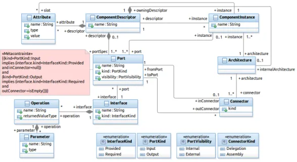
Our solution is embedded into an architecture description language called CLACS (pronounced Klax). CLACS is a general purpose ADL that enables constraint-component modeling and composition. It supports simple con-cepts which have been unified from existing ADLs (components, connectors, ports, interfaces, etc.). Its metamodel is depicted in Figure4. In order to not add (yet-)other constructs for constraint-component modeling, we chose to use the same constructs as for business component modeling. We have just stereotyped the metaclasses representing these constructs in the metamodel of Figure 4. In this component model, we distinguish between (constraint) component descriptors and (constraint) component instances (a dichotomy like between classes and objects). Descriptors specify checking ports, which
Figure 4: A Simplified Metamodel of CLACS
are a special kind of ports, described by “Checking” interfaces. In these interfaces, a developer specifies signatures of operations for architecture con-straint checking. These operation signatures are then associated by her/him to ACL constraints, which are the boolean expressions that are effectively checked. If a component exports a checking input port (it is thus described by a provided interface), this component is able to check the specified ACL constraint(s). If a component exports an output port (described thus by a required interface), this means that the operation signatures specified in the interface, which describes this port, are required by the component in order to be able to check its own constraint(s).
Constraint component descriptors can be primitive (for modeling simple constraints) or composite (for complex ones). If a developer defines a com-posite descriptor, she/he should declare, in the internal architecture of the descriptor, a set of constraint component instances that compose the con-straint and some “checking” (concon-straint) connectors. Concon-straint connectors link two checking ports (an output port to an input one). ACL constraints have as a context a metadescriptor of the business component which is nected to the encompassing constraint component. In the body of the con-straint (as shown in the example of Figure 5), the keyword self is replaced by context which is a special required port connected to this
metadescrip-tor of the business component4. Intermediate constraint components may
exist between a business component and a constraint component. Indeed, a constraint component may require another constraint component, which in turn requires a constraint component, and so on. In this case, CLACS mod-eling environment ensures a propagation of the context (the connection to the metadescriptor of the business component) to all constraint components, even those which are not directly connected to the business component in order to solve the context keyword in their ACL constraint specification. In addition, ACL constraints can use one or several output checking ports. These ports are used to call required operations, when composing constraint components (see subsection3.3). We have chosen to make required operation calls, in constraint specifications, through ports, because this is the natural way of doing in component-based development. We made this choice for being consistent and providing a unified modeling environment.
Constraint components can have states. If a developer defines a constraint component descriptor with several checking operations and if there is a shared navigation expression between ACL constraints in these operations, she/he can factorize this expression and declare it as the expression that evaluates a special private attribute of that component descriptor. This attribute is called an architecture constraint query in CLACS. The value of this attribute is evaluated once, when the constraint component descriptor is instantiated and connected to a business component. The value of this attribute can be used in the ACL constraints of the different checking operations of the constraint component descriptor. An example is given in Section 3.4.
3.2. Specifying Constraint-Components
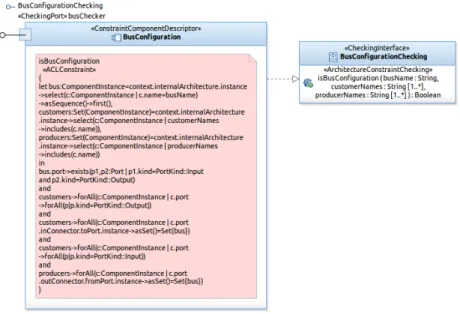
Figure 5 depicts a graphical representation of a simple (primitive – not composite) constraint component descriptor. This descriptor can be instan-tiated in an architecture description in order to check the Bus configuration architecture pattern (see Listing 2, Section 2). Each BusConfiguration instance owns one input port named busChecker that exports a constraint checking operation having the following signature (see right part of Figure5):
isBusConfiguration(busName:String,customerNames:String[1..*], producerNames:String[1..*]):Boolean
4This required port (context) and the connector to the metadescriptor are not
explic-itly modeled in the examples of this paper in order to not complexify the architecture descriptions.
Figure 5: Example of a Primitive Constraint Component
Each BusConfiguration instance can then be connected, through that checking port, to any business component requiring this constraint checking operation.
In contrast to the constraint shown in Listing2, the ACL constraint spec-ification in this constraint component5 uses the parameters declared in the operation signature (isBusConfiguration(...)). Indeed, this constraint needs the name of the component instance representing the bus as a simple String, the names of the component instances representing the customers, as a non-empty literal set of strings, and the names of the components repre-senting producers as a non-empty literal set of strings too. These parameters are used in the constraint specification as property call expressions.
When called within our modeling environment, a provided operation of a constraint component returns true if the architecture description of the busi-ness component to which it is connected fulfills the constraint. When such a connection is established, via checking ports, and a constraint evaluated, the context keyword is automatically solved to a connector to a metade-scriptor of the business component to which the constraint will be applied.
5Note here that the ACL constraint navigates in the CLACS metamodel (depicted in
Figure 4) and not in the UML2 one (as it has been done in Section 2). In this case, constraints are checked on CLACS architecture descriptions and not on UML component diagrams.
When composite constraint-components are built, in which a constraint com-ponent is connected to another one, a transitive closure is computed on that connector until a metadescriptor of the business component is found.
3.3. Connecting Business to Constraint Components
A business component, which embeds a constraint component instance (called here a constrained business component ) has a checking output port, which provides the modeling environment with the operation for running the constraint checkings. Within its internal architecture, a constrained business component descriptor declares one or several business component instances and one or several constraint component instances. They are connected to-gether using either traditional (business) connectors (between business com-ponents only) or constraint connectors.
Figure 6: Example of a Business Component connected to a Constraint Component
An example of such constrained business component is given in Figure6. This is a simplified view of the business component, where we show only constraint-related elements. Business operations provided by this compo-nent and ports of internal compocompo-nents are not illustrated in this figure. The component descriptor is named ESB. It declares, in addition to its business modeling elements, an instance of BusConfiguration, which exports the input port named busChecker. Since ESB is connected to a contraint com-ponent, an operation checkAC() is automatically added to the descriptor
Figure 7: Composition of Constraint Components
with a default implementation (a skeleton of an ACL constraint to be cus-tomized by the developer) in which there are calls to each operation provided by the embedded constraint components (in our example, there is only one operation call). This operation is the starting point used by the modeling environment for launching the evaluation of constraints, after instantiating this descriptor. The implementation of this operation is shown in the box at the bottom of Figure 6. It consists of calling the operation provided by the checking port busChecker. It passes to this operation the necessary ar-guments for its interpretation: the name of the component instance playing the role of the bus, and the names of the component instances playing the roles of customers and producers.
3.4. Connecting and Composing Constraint Components
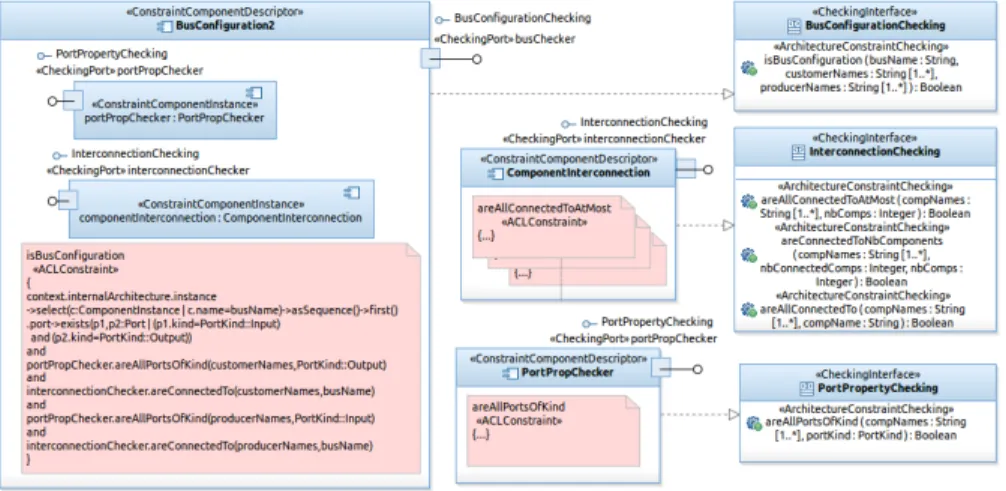
In the previous subsection, we have shown how to use an input checking port inside an ACL constraint specification. This constraint was defined in the specification of the input port ( checker) of a business component (ESB). In this subsection, we will focus on constraint components and will refine the definition of the constraint component descriptor BusConfiguration and decompose the specification of its ACL constraint into multiple parts. The new specification of this ACL constraint is given in Figure 7.
In the body of the constraint (see again Figure 7) there is a call to the operations areAllPortsOfKind(...) and areConnectedTo(...) pro-vided by two different constraint component instances (portPropChecker
and componentInterconnection). These instances are shown in the left of the figure. The first component checks the properties of ports (their kind here), and the second checks connections between components. They pro-vide many operations for constraint checking, among which the two opera-tions used in our example. These two instances are declared in the internal architecture of the BusConfiguration2 constraint component descriptor.
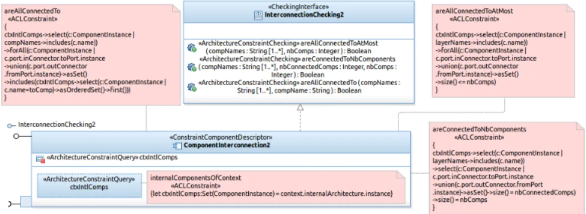
Now, we refine the description of the constraint component descriptor ComponentInterconnection. Since it includes several constraint checking operations which have a shared navigation expression in their ACL con-straints (context.internalArchitecture.instance), we added an archi-tecture constraint query (a special private attribute) named ctxIntlComps, which stands for the context’s internal components. Figure 8 shows the new descriptor of this component (ComponentInterconnection2). The ACL nav-igation expression is defined as an OCL-like let expression (see the bottom of Figure8). The ACL constraints in the checking operations use henceforth this constraint query (ctxIntlComps), which is evaluated only once. This is depicted in the three ACL constraints surrounding the component descriptor.
Figure 8: A Constraint Component Descriptor with a Query
4. Illustrating the Model
We show in this section how we can apply the proposed model to some examples of architecture constraints. In particular, we present three different examples in order to further highlight: i) in Example 1, the reuse of existing
constraint-components in the specification of a new constraint-component, ii) in Example 2, the composition of several constraint-components to build a more complex architecture constraint, and iii) in Example 3, the application of the model on a real-world case example.
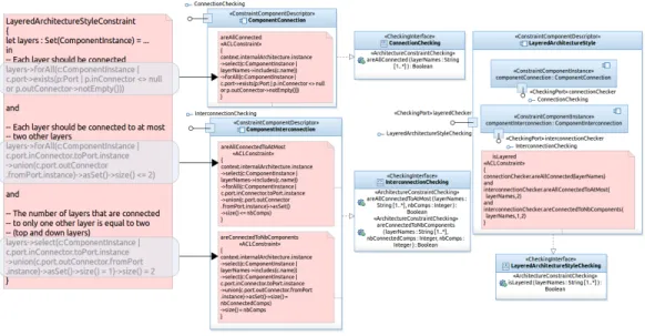
4.1. Example 1: A Variant of the Layered Architecture style
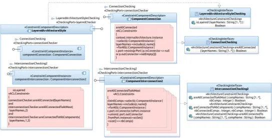
The constraint component enabling the checking of the layered architec-ture style, introduced in Section 2, is illustrated in Figure 9. It is composed of two primitive constraint components. One of the components is an in-stance of the same descriptor as the one instantiated in the description of the constraint component BusConfiguration2 introduced previously, which is ComponentInterconnection2. This time, we use another operation pro-vided by this component: areAllConnectedToAtMost(...) which checks if all the internal components of the context component are connected to at most n (received as an argument) components. The other internal constraint component is used for checking if all internal components of the context component are connected.
In practice, the constraint introduced at the beginning of the paper (in Section 2) can be used only with architecture descriptions where the whole internal architecture conforms to the layered architecture style. Indeed, we can observe that the constraint is expressed in a “context-independent” way: it checks that “all” internal components of a given composite component, whatever their number or name (and without referencing them explicitly), form a layered architecture. This is not always the case. In real-world sit-uations, architecture descriptions are configured as a layered architecture in some parts of the architecture, but they include in other parts some addi-tional components.
The constraint component descriptor of Figure9can be used in such sit-uations. The signature of the provided operation of this component includes the necessary parameter: isLayered(layerNames:String[1..*]):Boolean
The argument received by this operation is propagated to the operations of the internal components, as illustrated in the ACL constraint at the left of the figure.
The user of this constraint component descriptor should state (in the description of her/his business component), in a literal set, the names of the component instances playing the role of layers as following:
layeredChecker.isLayered(Set{’authenticator’,’accessAuthorizer’, ’localLogger’,’centralArchiver’})
Figure 9: Constraint Component for Checking the Layered Architecture Style
It is true that for this example of architecture constraint, we could simply state that the component instance of layer 1 must not be connected to the component instances of layer 3 and layer 4. In addition, there should be no connection between layer 2 and layer 4. However, the advantage of specifying this constraint in the way we have done is that it scales relatively well for a larger number of layers. If we have more than four layers, we have just to add the names of the additional layers in the literal set passed as an argument for the constraint checking operation.
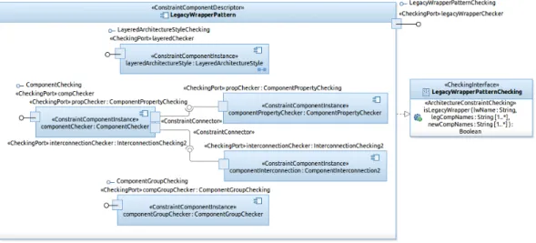
4.2. Example 2: Legacy Wrapper Architecture Pattern
We present here the application of our model on another (larger) example of an architecture pattern. The constraint component illustrated in Figure10
enables the checking of the Legacy Wrapper Architecture Pattern [15]. This pattern recommends the “isolation” of legacy systems from the new devel-oped components; all interactions between these two parts should go through a specific component, named a legacy wrapper.
This constraint component is composed of five component instances. The first component is an instance of the previous constraint component descrip-tor specifying the Layered Architecture Style. Indeed the Legacy Wrapper includes in its definition the constraints imposed by the layered architecture style. The architecture description of the business system respecting this pat-tern should include three layers: the new components layer, the legacy
wrap-Figure 10: Constraint Component for Checking the Legacy Wrapper Architecture Pattern
per (middle) layer and the legacy system(s) layer. In addition, the constraint component includes two other constraint component instances. The first one is responsible for checking the legacy wrapper component in the middle layer and some of its properties (ComponentChecker), and the second checks the groups of components inside the layers (ComponentGroupChecker). The ComponentChecker requires some external constraint checking, which is satis-fied by two other components: componentPropertyChecker and component-Interconnection. This illustrates the ability for constraint components to have output ports declaring some required constraint checking. For the sake of simplicity, we have hidden the constraint specifications checked by all these components.
4.3. Example 3: Architecture Constraints from a Real-World Component-based Application
Let us now consider an example of the architecture description of a real-world component-based application, together with its architecture con-straints. The modeled software system is a set of Eclipse plugins that pro-vide the Java programming environment JDT (Java Development Tools) in the Eclipse SDK. The architecture of this set of plugins is depicted in Fig-ure11. It has been defined starting from the OSGi meta-data of these plugins (the exported and imported packages and required bundles). For reasons of
simplicity, we have omitted some very simple component descriptors like JDT Annotation. In addition, we have hidden from component descriptions the interfaces required from the Eclipse Platform (required from the core plugins of Eclipse, like SWT – the Standard Widget Toolkit, or the Platform Runtime).
Figure 11: An Excerpt from the Architecture of Eclipse JDT
In one of the official technical documentations of Eclipse SDK [16], it is mentioned that the core components of JDT have been designed separately from the JDT user interface (see Section JDT Implementation in the previ-ous reference). This means that these components, which are JDT Compiler, JDT Core and JDT Launching, do not have required interfaces that are con-nected to JDT UI (or JDT Debug UI). The rationale behind this design choice is to “allow the JDT core infrastructure to be used in GUI-less configura-tions, of the Eclipse Platform, and by other GUI tools that incorporate Java capabilities but do not need the JDT UI” [16]. Besides this design choice, JDT APT6, a tool for Java annotation processing, and JDT JUnit, a tool for Java unit testing, are clearly supplementary plugins in JDT. The core compo-nents of JDT should not depend on them (should not have required interfaces connected to them). These two architecture constraints are specified using CLACS and integrated to the architecture of JDT as depicted in Figure 12.
Figure 12: Eclipse JDT Component connected to the Constraint Component
An instance of ComponentInterconnection2 is specified as an internal component of the new architecture description of the composite component Eclipse SDK (see the left of Figure 12). The operation existsDirectedCon-nection(...) which is provided by this instance is called within the checkAC() operation added to the JDT composite component (see the implementation of this operation at the top right of the figure). The implementation of the operation existsDirectedConnection(...) is given at the bottom right of the same figure. A constraint connector has been established between the two internal components. In addition another delegation constraint con-nector has been defined between the composite business component (Eclipse SDK) and its internal component JDT.
5. Implementation of the Constraint Component Model
We have implemented the constraint component model as a DSML (Domain-Specific Modeling Language) using the UML profile mechanism. In the past, we have developed another implementation as a new metamodel in Eclipse us-ing Ecore with EMF [11]. A UML profile implementation is a better solution
than an EMF-based one, because it provides a better integration in existing IDEs supporting UML modeling. All CLACS concepts have been designed as UML stereotypes that extend UML meta-classes such as: Component, Port and Connector. These stereotypes extend UML meta-classes having the same name, except ComponentDescriptor which extends Component, and ComponentInstance which extends Property.
We have extended this basic UML profile with concepts related to ar-chitecture constraints. In this specific profile, we introduced the concept of ACLConstraint, which extends UML Constraint metaclass, Architecture-ConstraintChecking stereotype which extends UML Operation, and Archi-tectureConstraintQuery stereotype which extends UML Property.
All diagrams depicted in the figures of this paper have been designed with this profile, which has been implemented in IBM SDP (Rational SoftwareR
Development Platform). The created profile can be used in other UML edi-tors. For example, the empirical evaluation, which is presented in the follow-ing section, has been performed usfollow-ing this profile within the Papyrus UML environment.
For ACL interpretation, we have developed a pre-processor7. Having the architecture description of business components and their connected con-straint components, ACL concon-straints are interpreted progressively by first, evaluating parameters and let expressions. New operations (definitions in Eclipse’s Complete OCL) are created on the fly and added (temporarily) to the UML metamodel. These operations contain the ACL expressions to evaluate, which are present in constraint components. The ACL constraint which is present in the “top-level” business component (the starting point of ACL interpretation – checkAC operation) is evaluated as an OCL invari-ant by the OCL interpreter provided by Eclipse MDT. The context of this invariant is the business component that embeds it.
6. Empirical Evaluation
The goal of the empirical evaluation presented here is to answer the fol-lowing question: “To what extent our component model enables reusability in the specification of architecture constraints? ”. We present first the metric we have used to quantify this quality attribute (reusability). Then, we show
on which data the evaluation has been performed. At last, we present and discuss the results and the threats to validity.
6.1. Reusability Measurement Method
In order to quantify to which extent the approach can enable reusability, we should use an appropriate metric. Frakes and Terry in [17] reviewed six categories of metrics and models of software reuse. They cover the reusability of different artifacts in a software project, such as: source code, architecture, data, documentation, etc. Most of the surveyed metrics focus on long term reuse activities where the reuse level is tracked throughout the lifecycle of artifacts. In our work, the evaluation focuses on a given set of data where each entity is not supposed to go through different development phases. Therefore, we choose the cost-benefit analysis category to measure the level of reusability supported by our approach. In general, metrics in this category estimate the cost of developing a system without and with reuse and from that, show the benefit of the reuse support. Of these metrics, we choose the one proposed by Gaffney and Durek [18], and which is defined as follows:
C = (b + (E/n) - 1)R + 1
where:
C is the cost of software development R is the proportion of reused elements
b is the cost of incorporating the reused elements into the new product E is the cost of developing a reusable element
n is the number of uses of reused elements
Some clarifications need to be made about this formula. C is one impor-tant indicator of the effectiveness of the reuse method. If there is no reuse at all, C is equal to 1. The more effective the reuse approach is the less C is. For instance, C equals to 0.8 indicates that the cost of software development decreases to 80% thanks to the reuse method. b and E reflect the estimated cost of incorporating and developing, respectively, the reused elements. b is supposed to be greater than 0 because it always takes effort to apply the reuse method. E is supposed to be greater than 1 because the creation of a
reusable element requires an extra effort. Basically, E is the sum of the costs of developing a new element (without reuse support) and applying the reuse method.
6.2. Experiment Data
As data for our experiment, we chose as architecture constraints the topo-logical conditions imposed by architecture patterns (AP) for many reasons: i) APs are widely used as a means to characterize an architecture, ii) they are well documented in the literature, iii) they apply to component-based architectures, which are the context of our work, and iv) their topological conditions are considered as a suitable way to document a part of design choices. Moreover, in the following sections we will show that this collec-tion of architecture patterns is where the reuse of constraints takes place and where our approach can be leveraged to facilitate it. We collected APs from different sources [19, 20, 21] and we considered only those related to the structural aspect of the architecture. We identified 31 patterns including their variants. A variant represents a way of applying a pattern to a specific context of an architecture. For instance, a pattern can relate to all elements in an architecture or only to a subset of them, which is the case when the pattern must also take care of filtering the related elements. Since each pat-tern variant exists independently and the constraints imposed by it have a different specification (because the architecture description is analyzed dif-ferently within the constraints), the choice of differentiating and including pattern variants in our experimentation does not bias its results.
For each pattern we identified from its textual definition a list of con-straints that formalize the topological conditions imposed by it. Each ele-ment of the list was impleele-mented as a constraint component. We refer to this kind of constraint components as basic constraint components. The pattern is composed of these basic constraint components, and by itself is a constraint component. We refer to the latter as a pattern constraint component. So, the pattern and its basic constraint components are added to the global list of constraint components. The complete set of “formalized” architecture pat-terns is described in a technical report [22]. Patterns are numbered from 1 to 31 (numbers are indicated between brackets in the titles of each subsection detailing a pattern) and are presented in pages 4 to 10 of this report.
During the “formalization” of a pattern, some of its basic constraints may be already specified. This situation implies a reuse of already defined basic constraint components for its definition. When the definition of a pattern as
a pattern constraint component includes all basic constraints from another pattern we consider that the former includes the latter. Thus, to measure the reusability we rely on these relationships.
6.3. Experiment Measurement
We performed some measurements to quantify reusability for the formal-ized patterns. In particular, we measured the reusable part (proportion) in the component-based specification of architecture constraints of each pattern (the R value) and the number of reuses of each component (the n value).
6.3.1. Measure of the proportion of reuse in each pattern
As presented in Section 6.1, the R value represents the proportion of reused elements in each entity. In the case of our experimentation, it rep-resents the proportion of the pattern’s structure (a set of constraint com-ponents) which is issued from reuse (used by other patterns). This reused structure could be a basic constraint component or a pattern constraint com-ponent. Figure13shows the values of R for all pattern constraint components (P1 to P31 documented in [22]). As we can observe, the R value lies in the range of 40% to 100%. What is noticeable is that there is up to 58% of these pattern constraint components having 100% of their structure issued from reuse. This reinforces our observation that architecture patterns have potential to be designed from a reusable structure.
6.3.2. Measure of the number of occurrences of reuse
Another value to be measured is n, which represents how many times a set of constraint components is reused in the whole set of constraint com-ponents. To measure n, we counted the number of occurrences of a basic constraint component or a pattern constraint component in the structure of other constraint components. Figure 14 depicts the number of times basic constraint components (C1, C2, ... documented in [22]) are reused. The result shows that there is a great number of basic constraint components that are used in at least two different pattern constraint components. More specifically, 47% of these basic constraint components are reused. Especially, there are two basic constraint components that are used in more than 40% of pattern constraint components. The first one checks whether all compo-nents in a given architecture description are connected, and the second one checks that all connectors between each pair of components must go in the same direction. Indeed, these two constraints are often required by most of architecture patterns.
Figure 14: Number of times basic constraint components are reused
Another similar calculation is performed on pattern constraint compo-nents instead of basic constraint compocompo-nents. Indeed, pattern constraint components, which are created by composing basic constraint components, can themselves be reused to construct more complicated patterns. In other words, this reflects the reuse of constraints at a higher level of abstraction.
Figure 15 depicts the number of times pattern constraint components are reused. 5 out of 31 pattern constraint components are reused. Especially, the pattern constraint component (P6) formalizing the Layered architecture style/pattern is reused 4 times respectively in the constraint components of the following patterns: Layered Pipe and Filter, N-Tier architecture, Legacy Wrapper and Pipeline. This is understandable because all of these four pat-terns are special cases of the Layered architecture pattern. Although there are only 5 out of 31 pattern constraint components being reused to build the structure of others, this demonstrates the potential to promote the reusability of pattern constraint components in the construction of a pattern constraint component library.
Figure 15: Number of times pattern components are reused
6.4. Experiment Result and Discussion
In this section we present the calculation of the C value for each pattern constraint component. C represents the cost of constructing an entity taking into consideration the reusability of its structure. The less C is, the more effective the reuse brought out by the component model is. R and n values for each pattern component are drawn from Section 6.3. b in our evaluation is the cost of composing constraint components and E is the cost of developing constraint components (e.g. creating ports or connectors). We take the b and E values estimated in an industrial case study performed in the early ninties on Ada components [23]. In this case study, the author identified five categories of components according to their complexity, each of which
having its own values for b and E. Here are their descriptions given by the author [23]:
Monolithic Components in this category are found to have a similar com-plexity, both in development and in integration into development code Polylithic Components in this category are found to have a similar
com-plexity regarding integration into development code
Graph The graph component is the most complex in the repository which can be considered as a nontrivial, domain-independent reusable component. We cannot find any similar complexity among these components both in development and in use
Menu and Mask These are end-products of the project
Constraint-components fit in the “Polylithic” category, because these have the same complexity regarding their integration into a composite constraint component descriptor, and regardless the integrated constraint-components. Indeed, the integration consists always in: i) instantiating the constraint com-ponent descriptor, ii) connecting it to other instances, and iii) invoking its operations. Even if invocations require sometimes argument passing, these arguments are always literal values (strings and collections of strings in the considered catalog). This makes invocations simple and homogeneous among constraint components of the catalog. In addition, invocations always return boolean values. This does not require any parsing of the returned values in the composite component where invocations are made. In this category, b and E are evaluated by the authors to respectively 0.15 and 1.2. It is true that not being able to measure b and E means that we do not exactly measure the impact of using component-based development in the reuse of constraints. This is mentioned later as a threat to validity. But even so, we found that 0.15 and 1.2 reflect well their proportion to the cost of developing a product from scratch (the unity, 1): i) b, the cost of integration (instantiation, con-nection and invocation), which is a recurrent task, represents roughly the 7th (1/7 ' 0.15) of the cost of development of the parts not issued from reuse; ii) E, the cost of developing a reusable element, is greater than developing a non-reusable element (> 1). It is a fifth (1/5) greater (1.2). This is the cost of making an element reusable: declaring the constraint’s embedding component descriptor with its ports and the provided/required interfaces.
Figure 16: C value for patterns
Figure 16 shows the cost of constructing 31 pattern constraint compo-nents. C varies from 28% to 82%. As we can see, all of the constructed pattern constraint components have a cost less than 1 which means that the reuse really has an effect in reducing constraint component construction cost. For instance, the Layered Pipe and Filter pattern component (P9) has the cost of 28% which can be explained by the fact that 100% of its structure can be reused and moreover, its internal structure (Layered (P4), SameDi-rectionConnectors(C12), RestrictedLeftMostComponent(C15) and Restrict-edRightMostComponent(C18)) is the one being most reused. Details about each pattern constraint component can be found in the aforementioned re-port [22].
Finally, the average cost of constructing all the catalog’s pattern con-straint components is measured as the sum of the costs of all pattern com-ponents that are not entirely reused, divided by the total number of pattern components. The reason why only the cost of pattern components not being entirely reused is involved in the calculation is that as long as a constraint component is entirely reused, its cost is already distributed when measuring the cost of the reusing components (E in the metric’s formula in Section6.1). If we take into consideration the costs of all the pattern constraint compo-nents, these costs (of initial construction) will be replicated. And this will
alter the measurement of the average cost. We obtained for this average cost 40,09% which is a reasonable value to justify the effectiveness of reuse brought by our component model.
6.5. Threats to validity
In our case, the internal validity concerns the confidence we have in the correctness of our pattern definitions. The external validity concerns the reproduction of our evaluation in other contexts.
6.5.1. Internal validity
Sometimes, the description of an architecture pattern implicitly imposes some constraints that we have involuntarily forgotten (not specified). We mitigate these risks by having pattern constraints drawn from many different sources. Thus, we are pretty confident with the correctness of our pattern catalog.
The determination of constraints in patterns could be biased by the fact that the number of researchers (three) participating in the pattern constraint specification process is limited. However, we conducted our experiment on a relatively large set of data and we made sure that the way each pattern is elaborated using constraint components is the most representative one.
6.5.2. External validity
The data is gathered from existing architectural patterns from the liter-ature. However, the use of our evaluation process is general but should be also applied to other domains of constraint usage (for instance, SOA pat-terns [24] or OOP design patterns [4]). Nevertheless, the catalog of patterns we collected is quite large (31 variants of different patterns) and we expect them to be representatives to the typical use of architecture constraints.
7. Related Work
Our work is compared here with different works in the literature, or-ganized in four different categories. First, we present the works proposing models and languages for design-time reuse of architecture constraints, by focusing mainly on existing ADLs. Then, we list the works dealing with implementation-time specification and reuse of architecture constraints as-sociated to programs. After that, we expose existing techniques for reusing OCL constraints, since our model is based on this standard language. At
last, we show existing quality models enabling reuse and composition of con-straints.
7.1. Architecture Constraint Reuse at Design Stage in ADLs
In the literature, there are many ADLs that provide capabilities for archi-tecture constraint specification. Among these ADLs, we can quote Acme [25], Aesop [26], Wright [27] and SADL [28, 29]. Aesop is one of the first ADLs having proposed a constraint language. The authors use the terms “style or topology constraints” and “configuration rules” for referring to architecture constraints. These are written in methods in classes, and checked during architecture description validation. In these methods, the architect uses an API called FAM (Fable Abstract Machine) for introspecting architecture de-scriptions.
SADL is an ADL enabling the specification of constraints (called by its authors Well-formedness Rules) for formalizing architecture styles. It introduces a syntax for expressing predicates in the first-order logic in order to restrict the types of elements composing an architecture description or a style specification (components, connectors, ports, etc.). In SADL, there are some basic types representing architecture elements structure and behavior, without any constraint. Then a new architecture description or architecture style should introduce subtypes (by inheritance) with possible additional constraints. These are checked during the interpretation of primitives for instantiating components or connectors and connecting them.
Wright (a succesor of Aesop) is an ADL used to define formal specifi-cations of architecture descriptions. This language provides some language constructs for specifying architecture constraints.
Acme embeds Armani [30], a first-order predicate language which enables the specification of architecture constraints: invariants and heuristics. Invari-ants should not be violated, however heuristics should be observed but can be violated. In order to specify reusable constraints, “design analyses” can be used. These are functions, like CLACS operations, that can be called from other design analyses, from invariants or from heuristics. To specify a con-straint in Armani, we need to choose between: i) a design analysis (a reusable constraint as a function) and an invariant/heuristic, where we call this func-tion, or ii) only an invariant/heuristic. In CLACS, we specify a constraint component providing an operation (function), and then we connect it to a business component, where we want to check the constraint, and where we call this operation via a port. Thus, in CLACS there is only one concept for
representing business entities and their associated architecture constraints. In addition, in Armani we did not find how to specify architecture constraints (design analyses and invariants or heuristics) independently from a style or a system instance definition. And if they can be defined independently, we did not find how to reuse them (import their definitions). In CLACS, architec-ture constraints are “first-class” entities that can be specified independently and resused in different contexts.
Aesop, Armani and WRIGHT provide style refinement mechanisms. In-deed, in these language, we can define some styles as refinements of other styles in which we can add constraints or specialize types of architectural elements.
Reuse in these languages is implemented by inheritance. In our case, reuse is implemented by composition. Inheritance and composition are two complementary mechanisms in software reuse. Each one offers an interest-ing reuse schema in a given situation. But in our context of architecture constraint specification, in the situations we have encountered when reusing constraints, we have either added or removed constraint parts to/from ex-isting constraints. We have not had to redefine a constraint part. We think thus that inheritance is not a pertinent solution for architecture constraint reuse. However, inheritance certainly makes sense in reusing specifications of architectural styles or patterns (which are different from architecture con-straints).
FScript8 is a scripting language for the reconfiguration of Fractal [31]
component-based architecture descriptions. It provides a way for writing actions (reconfigurations with side effects) and functions (architecture con-straints without side effects). It has a syntax for introspecting architecture descriptions (FPath) which is based on XPath.
In FScript as in CLACS, we can write parameterized architecture con-straints. In addition, the authors of FScript state that it is possible to call existing functions inside FPath requests. We assume more generally that we can call functions representing architecture constraints inside functions representing other architecture constraints for composing them. In contrast to CLACS, FScript’s architecture constraints are defined in scripts outside architecture descriptions and are checked by external tools. This does not
8A Tutorial of this language is available for download in an SVN repository of OW2:
provide a unified paradigm/environment for software architects, where con-straints are defined, reused and then checked with architecture descriptions. AADL [32] (Architecture Analysis and Design Language) is an ADL for describing (software and hardware) architectures of embedded and real-time systems. Originally, this language does not provide a constraint language. REAL [33] (Requirements and Enforcements Analysis Language) is a lan-guage which has been proposed as an extension to AADL for expressing architecture constraints. This language enables to write constraints as the-orems that apply to collections of architecture elements (components, con-nectors, etc.).
Constraints in this language use an architecture analysis mechanism for getting in an architecture description the set of component instances of a cer-tain type (Thread, Data, etc.), the values of their properties, or for testing the access or the connections between component instances (Is Accessing To(...), Is Bound To(...), Is Subcomponent Of(...), etc.). These high-level op-erations correspond to the checking opop-erations we have shown in CLACS constraint component examples (areAllConnectedTo(...) provided by the component ComponentInterconnection). This however is a fixed prede-fined set of operations that cannot be extended by the language users. In our model, an architect can write as many architecture constraints as she/he wants, and then reuse them by instantiating their embedding components.
In [19, 34], the authors propose to use a number of “architectural prim-itives” to model architectural patterns. Through the stereotype extension mechanism of UML, one can define architectural primitives to design a spe-cific structure [19] or behavior [34] of a pattern. Each primitive is a tangible modeling element with its own semantic that can be composed to form a pattern. In our work, a pattern constraint component is logically decom-posed into basic constraint components. In other words, a basic constraint is not necessarily a modeling element in a pattern but a part of the logic of the pattern. Looking at pattern composition [35] from this point of view helps us modeling patterns with more fine-grained logic, e.g. a structure that imposes connectivity or an acyclic graph.
7.2. Architecture Constraint Specification and Reuse at Implementation Stage In the literature, there is a great number of languages which has been pro-posed for defining architecture constraints on object-oriented programs [36,
37,38,39,40,41,42,43,44,45]. Some of these languages refer to architecture constraints as conditions on structural dependencies. These languages vary