R. Pasupathy, S.-H. Kim, A. Tolk, R. Hill, and M. E. Kuhl, eds.
MODELING COMPLEX PROCESSABILITY CONSTRAINTS IN HIGH-MIX SEMICONDUCTOR MANUFACTURING
Ahmed Ben Amira1,2 Guillaume Lepelletier2 Philippe Vialletelle2 Stéphane Dauzère-Pérès1 Claude Yugma1 Philippe Lalevée1 1
Department of Manufacturing Sciences and Logistics Ecole Nationale des Mines de Saint-Etienne – CMP
F-13541 Gardanne, France 2
STMicroelectronics
Centre Commun de Microélectronique de Crolles F-38926 Crolles, France
ABSTRACT
In semiconductor high-mix fabs, several technology nodes are run on the same line, using tool types from different generations. In this context, processability is a function defining which products can be pro-cessed on a given machine considering the current status of both the product and the machine. So in a high-mix context, having an information system that provides reliable information on processability and that can support the evolution of processability rules is fundamental. In this paper, we analyze the key elements for such a system. Based on the example of the implementation of fab constraints at STMicroelectronics’ Crolles300 production unit, we illustrate the consequences of the integration of new processability rules and propose flexible and agile UML class diagrams enabling information system to meet evolution requirements. The approach is validated on real fab data, and its impact is discussed. 1 INTRODUCTION
The functionality of information systems is no longer limited to decision support. With the ever-increasing automation of manufacturing and decisional processes, information systems are now at the heart of the enterprise operations. This situation is more striking in the semiconductor industry character-ized by the complexity of the production environment (Mönch et al. 2011; Chien et al. 2011). This is due to the high degree of automation of its production processes and functional convergence of its various businesses (Dauzère-Pérès, Yugma, and Sarin 2011). Thus, the semiconductor industry evolves in a com-plex environment in which strategic IT alignment must be ensured (Chen et al. 2008).
Companies, and especially semiconductor manufacturers, operate in a situation where they undergo changes in their business environment both internal and external. Practically, this translates in evolutions of organizations and hence business processes. To follow these evolutions, information systems must stay aligned with business processes to ensure the best possible performance. However, integrating new busi-ness requirements on existing systems is most of the time very difficult (Goepp, Kiefer, and Geiskopf
2006), especially when the goal is to achieve IT / business alignment (Henderson and Venkatraman 1993; Ullah and Lai 2013). Two scenarios generally occur:
• A complete overhaul of the complete information and control system (rebuild from scratch). This case is extremely expensive and only applies during complete system redesign. The main advantage of this approach is the exact translation of the business requirements, provided these requirements are cor-rectly and exhaustively expressed, which may very often be the first major difficulty.
• The adaptation of the existing information system to integrate the new requirements. The main issue in that case is the definition of “real” user needs. Due to constraints such as cost or delay of imple-mentation, users may not express their actual needs rather thinking in terms of small evolutions of the existing application. In other words, requirements are conditioned by existing systems, hindering the breakthrough and thus impacting the potential gains targeted initially.
Ideally, requirements should be expressed regardless of the existing systems, and then adapted during the design phase of the solution when taking into account constraints such as cost, delay of implementa-tion and business continuity.
Nevertheless in the industrial reality, capturing the “real” requirements is most of the time impossible. So formalizing business needs, verifying the relevance of requirements and finally validating the accuracy of the solution implemented is very difficult (Chapurlat, Kamsu-Foguema, and Prunet 2003) and thus overlooked because of planning constraints. To overcome these difficulties and ensure the sustainability of the operations as much as possible, it is then necessary for information and control systems to be able to meet change requirements while continuing to fulfill their intended functions.
The best feasible solution may be the introduction of a level of abstraction between information sys-tems and business needs. This “functional view” or meta-model will guarantee the evolution and adapta-tion of soluadapta-tions without affecting the expression of actual business needs. In that way, companies will develop a flexible and agile information system that can respond and adapt to business changes (Avila, Goepp, and Kiefer 2010).
In order to illustrate this approach, we present in this paper the notion of processability and its evolu-tion in the 300mm wafer fab of STMicroelectronics in Crolles (called Crolles300). We will concentrate on the evolution of specific processability rules (fab constraints) and investigate the consequences of their integration in the factory information and control system.
The paper is organized as follows. Section 2 introduces processability items (including the description of fab constraints) and the modeling consequences of the currents fab constraints. Section 3 presents reengineering guidelines. New models are defined to satisfy the fab constraints “real” requirements and to support the integration of any evolution of processability rules. Some industrial results of the tests carried out using the proposed models are shown and discussed in Section 4. Finally, in Section 5, we draw con-clusions and outline some important perspectives.
2 PROCESSABILITY IN SEMICONDUCTOR, CASE OF A HIGH-MIX SEMICONDUCTOR MANUFACTURER
To understand the concept of processability, we first need to introduce the notion of process flow in semi-conductor manufacturing. Electronic components are produced on silicon wafers. These wafers are grouped by “lots” of 12, 20 or 25 wafers. Each lot corresponds to a given product (i.e. type of electronic component). The process flow or “product route” is specific to each product. It is the ordered list of pro-cess operations to be performed on silicon wafers in order to obtain functional electronic components. Each operation consists of several individual steps which have to be performed on specific toolsets, taking into account performance or quality requirements linked both to the operation and the product to be pro-cessed. The junction between the “logical” operation and the “physical” equipment is realized through the process recipe. The process recipe, when considered from the tool standpoint, lists all the individual
oper-ations to be performed by each component of the tool (process chambers, modules, pumps, etc.), hence the setting corresponding to these steps (gases and chemicals to be used, flow, temperature, pressure, voltage, intensity, power, etc.). For each product and operation, several choices may be possible for the tool to be used, depending on several criteria such as recipe availability, tool performance, module or chemical availability, etc. The function giving for a lot l, a time t and an operation o the list of tools avail-able for processing l is called processability. It has to be noted that the term processability is also used for the function giving for a machine m at time t the list of processable lots.
The concept of processability is obvious for most industries, where it may be reduced to machine set-up and tuning. But in the semiconductor industry, due to the complexity of operations and the reentrancy of process flows, it is a major difficulty with direct impacts on the management of production lines (Fu et al. 2010). It is especially true in a high-mix environment where several hundreds of different products (i.e. “references”) are produced in parallel. This is even worse when considering medium volume fabs which generally have heterogeneous toolsets as in Crolles300. This may explain why, although the processabil-ity information is essential for managing production lines, only a few papers considered this feature in their scheduling models; see (Fu et al. 2010) for a literature review. And among those referring to the pro-cessability concept (Fu et al. 2010; Johnzén, Dauzère-Pérès, and Vialletelle 2011), it was still regarded as binary information without trying to characterize its construction.
2.1 Processability Items
In this section, we propose to describe the logic used for the elaboration of processability. This descrip-tion is valid for all semiconductors manufacturers whatever the mix and volume condidescrip-tions of operadescrip-tion. The main particularity when considering high-mix manufacturing is the continuous evolution of technol-ogies and the heterogeneity of the toolset. The setting of processability rules is then more complex (more “parameters” to take into account) and new rules are introduced more frequently.
From a modeling standpoint, processability items can be divided into four classes:
• Qualification: Defines if a tool has been certified to perform a given process, i.e. to produce a given type of products at a given operation of the flow.
• Resources availability: Defines which resources (tracked in the information and control system) are needed to perform the considered process. Resources include hardware (process module, chamber, transportation, measurement, etc.), chemicals but also logical settings (regulation or compensation loop, performance, etc.). It can even extend to human resources (certified operator, technician, etc.). • Material to be processed: Depending on the criticality of the product and operation to be processed,
the risk one is ready to take on the product may differ. Engineering or development wafers will for example be less critical than sellable products.
• Process restriction: Because each machine has its own lifecycle, temporary restrictions of the quali-fication perimeter may apply due to lower performance (end of consumable life, unavailability of a module, etc) or because of line management decisions (management of Preventive Maintenance, tool dedication, etc).
The above items are further detailed in the following sections. 2.1.1 Qualification
The first step of qualification is recipe availability. In order to perform the process required at a given production step, the equipment must be able to perform the required physical transformation. The recipe defines the conditions in which process must be done. For example, a recipe lists the gas pressure, the composition of the gas mixture, the temperature to be used, the various timings to be applied for ramp-up,
ramp-down, etc. As the machine may not be configured to meet these requirements, some changes may be needed in its configuration and, later on, parameters may be adjusted to get the intended process. That is basically the job of process engineers who will also set relevant monitoring and control procedures to guarantee process quality and stability (Johnzén, Dauzère-Peres and Vialletelle 2011). Once the consid-ered recipe has been created (on the machine server) and validated (result is conform to what is intended), the recipe is available on the tool. The next step is the tool qualification.
The high level of Quality standards at work in the semiconductor industry requires the certification of each machine used on every process step where it is used. Qualification criteria vary according to product requirements: from very loose for “Non Product Wafers” (used to test and tune the machine) to extremely restrictive for automotive products for example. Qualification of tools increases the flexibility and capaci-ty of the production line. In an ideal configuration all tools should be qualified for all recipes. However, in a high-mix fab generating thousands of recipes, qualifying all tools would be overwhelming.
2.1.2 Resource Availability
From a logistics perspective, the availability of resources for production operations must also be checked. Any limitation of the following points will impact lot processability:
• Equipment: The physical support to perform process is the equipment (tool, module, etc.). Also, processability evaluation should take into account other production tasks for this equipment.
• Consumable: This includes all the elements necessary to carry out the process execution in terms of chemical materials to use, gases, fluids, mask set, etc.
• Operator: Usually, each operator is assigned to one or more tools to ensure its maintenance or to su-pervise process activities. The operator has to be certified, i.e. trained and qualified on the considered toolset and operation.
• Automated Material Handling System (AMHS): Transport operations must be controlled to be in line with the orders given by the Manufacturing Execution System (MES) (Kiba et al. 2009).
2.1.3 Material to be Processed
The evaluation of processability must consider the type of product to be processed. Indeed, we must re-spect the compatibility between lot type and equipment status. In many other industries, this notion of compatibility does not exist and only the maintenance status is considered. The main lot types used at Crolles300 are listed below.
• Production lot: This category groups the product lots which are to be delivered to an external cus-tomer. They are also called “sellable” products.
• Engineering lot: The qualification process uses engineering lot to conduct the necessary tests. This type of lots is also used to improve process robustness, performance and yield.
• R&D Lot: These lots are similar to production lots but with more process customization. They are used for developing new technologies and sometime for prototyping new products.
• Non Productive Wafers (NPW): Based on maintenance interventions, NPW lots are used to verify equipment's aptitude to switch back to production status.
Aside from equipment qualification required by the customer, some critical products have to be real-ized while taking into account quality and performance indicators. For example, some products at some operations (critical steps) may only be processed on equipment having a performance greater than a cer-tain threshold. The purpose is to choose the best tool; we then talk of golden equipment notion. We note that this notion should be dynamic because equipment cannot always keep the same performance.
2.1.4 Process Restriction
The qualification of adequate tools for a recipe is a necessary but not sufficient condition to rule on the processability assessment. Indeed, the qualification scope may be restricted temporarily by banning sub-sets of the process plan: In case of process excursion, which may be detected by classical SPC, FDC, or other advanced process control techniques, a piece of equipment may be temporarily held until root cause identification and fixing.
Limiting production capacity disturbs production lines with significant economic consequences (Johnzén, Dauzère-Peres and Vialletelle 2011; Mönch et al., 2011; Kabak et al. 2013). So coordinating the various components or levers of processability is tricky because of the impact on quality on one hand and on capacity (hence delivery) on the other hand. Above all, these levers are very intricate and their management is distributed over numerous actors from different organizations. Moreover, generating rules from distinct business processes (maintenance, device/process engineering, quality, etc.) increases the dif-ficulty of the evaluation. The key to success is to have an information system that can coordinate all pro-cessability items and more importantly support their evolution.
In the following, we present the approach that was used at Crolles300 for this evolution. 2.2 Evolution of Processability Items
Semiconductor manufacturing is characterized by the rapid evolution of its technologies involving con-tinuous and significant changes in business requirements. New technologies are introduced at a rapid pace causing permanent changes in processability items, both in terms of parameterization and introduction of new constraints. In this context, the ability to easily adapt the information system is a real limitation to the overall performance of the organization.
Considering the case of the 300mm unit of STMicroelectronics in Crolles, the integration of new processability rules has been done by adding an additional layer (named fab constraints) to the MES. Given the constraints of time and the cost of integration, these new "processability rules" were imple-mented using SQL. Such a coding provided flexibility and so allowed to quickly take into account any type of specification. For example, it was possible to ban the process of a lot on tool B as soon as tool A is available (tool A preferred over tool B), or to prohibit a tool to perform a set of operations excepting one part, etc. In addition, each new processability rule results in a new set of fab constraints, one per tool, even if it is the same requirement that has to be applied for different tools. A typical fab constraint has the following structure: Name of the equipment to be considered, functional description of the constraint and the corresponding SQL script. For example, in Table 1, the constraint aims at prohibiting the use of masks with references under "1A24A" except for the "IXXX" technology. To apply the same restriction to tools “L248C04” and “L248C05”, two fab constraints were created.
Table 1: Examples of fab constraints structure.
Equipment Description Expression
L248C04 Mask < 1A24A prohibit except techno IXXX
(SUBSTR(FABLOTEXT.RETICLEFAMILY,1,5) < '1A24A' and SUBSTR(FABLOTEXT.RETICLEFAMILY,1,5) not like 'IXXX%')
L248C05 Mask < 1A24A prohibit except techno IXXX
(SUBSTR(FABLOTEXT.RETICLEFAMILY,1,5) < '1A24A' and SUBSTR(FABLOTEXT.RETICLEFAMILY,1,5) not like 'IXXX%')
Despite short-term benefits of the SQL solution, this method has shown its limitations in the medium term and long term, as discussed in the next section.
2.3 Fab Constraints: Current Modeling Consequences
Given the flexibility and the ease of their implementation, the number of fab constraints has rapidly in-creased to reach nearly 1,500 rules at Crolles300. The model was then so huge that the drawbacks of the solution became evident to everybody.
• Traceability of requirements: The implementation method has blurred the user requirements, since the documented description is not always sufficient to understand the intended restriction.
• Readability of the model: As mentioned in Section 2.2, engineers continued to create new fab straints even if there were others fulfilling nearly the same requirement. As duplicating fab con-straints is very risky, because of potential overlap, all fab concon-straints have to be checked one by one at every update.
• Processability assessment time: As fab constraints are basically SQL queries to the MES database and as all of the relevant fab constraints must be evaluated each time a lot is to be processed on a tool, the MES response time became critical (full automation context).
• Fab constraints restriction perimeters: Over time, the restriction perimeter of fab constraints be-came harder to pinpoint (except by MES experts). This is due to the use of wildcards and also to the partial authorization logic (in some cases).
Basically, even if very smart at the beginning, the solution chosen for the implementation of fab con-straints in the MES transformed into a black box, because of the accumulation of rules generating lack of visibility over processability. As the evaluation of processability became very expensive in terms of com-puting time, the performances of scheduling and dispatching applications were potentially impacted. Nev-ertheless the main problem of fab constraints was their maintenance with respect to the integration of new technological requirements. The approach presented in next section was then proposed to streamline the model and ease the evolution of the information and control system with respect to new business require-ments.
3 MODELING FAB CONSTRAINTS
Integrating new constraints on a complex and already existing information system without disrupting cur-rent applications is a huge challenge. Most of the time, the technical solution available will prevail and bias the expression of the actual requirements. That was the case for fab constraints at Crolles300. Basi-cally, engineers started from the functionalities offered by the information system, i.e. direct SQL queries on MES database and aligned user needs accordingly.
To overcome this problem, the authors had to define a new model, using UML class diagrams, to ex-press the actual user requirements previously embedded in fab constraints. The biggest challenge was to come to a level of abstraction sufficient to guarantee the adaptation to change.
In this section, we define the reengineering guidelines that were used to identify the original require-ments embedded in fab constraints and to express them as real functional requirerequire-ments.
3.1 Reengineering Guidelines
In order to modify the expression of fab constraints from SQL scripts to a model view in UML class dia-gram, modeling guidelines were defined. The goal is to overcome the current limitations of fab con-straints while anticipating potential future needs. These guidelines satisfy the following criteria:
• Always use the same modeling choice for similar problems even though different choices exist. Also, different types of problems should not be addressed by the same modeling solution.
• Take into account the exact business need or requirement. For example, if the process of a given product has to be prohibited on a piece of equipment, the proposed model should allow excluding that product from processability items.
• Opt for the modeling option that ensures the maximum flexibility, i.e. which provides the maximum margin of configurability. Similarly, in order to ensure agility issues, these choices should not con-demn future evolutions of the model. This also means that, when dealing with a given case study, it is important to extend the reasoning to closely related problems.
With these guidelines in mind, fab constraints were reengineered and a new model was defined. It is presented in the following sections.
3.2 Scope of Application / New Model
Starting from SQL scripts and discussing them with end users, it was possible to capture actual require-ments and to classify fab constraints by scope of application.
• Qualification: It is the same concept as described in Section 2.1.1 enriched by the notion of context of utilization.
• Process restriction: It is the same concept as described in Section 2.1.2 but with an increased com-plexity.
• Linked process: It steers a lot to use the same equipment at different process stages.
• Quality criteria: It is a processability concept with preference (which can sometimes be strict). Then, respecting the reengineering guidelines described above, new UML class diagrams were de-fined, covering all the processability rules currently covered by fab constraints and minimizing the cost of the integration of new processability rules. In the following, we present each scope of application. Due to lack of space, further details on the proposed UML class diagrams will be presented in another paper. 3.2.1 Scope: Qualification
The logic of the qualification is that recipes are banned by default. In other words, an action has to be per-formed at recipe level to allow its process on the considered tool. That is the qualification process. More-over, note that recipes can be common to different technologies. Thus, qualifying an equipment recipe no longer makes sense and in order to clarify the qualification context, one has to consider both the technol-ogy and the step level or operation of interest.
The advantage of this model is to provide visibility on the overall capacity of the fab in terms of qual-ified equipment, non-qualqual-ified tools that could be qualqual-ified and others.
3.2.2 Scope: Process Restriction
Following the logic presented in Section 2.1.4, various process restriction elements have been identified. They are called levers in the following as they are really seen as the way to shape fab capacity, hence the management of production flows. The main difficulty was to select and define the right levers, i.e. those which enable to reproduce each and every recipe or process restriction scheme in the simplest possible way. As some of the existing restrictions are very complex, logical combinations were used. Sub-restrictions were then defined using a logical AND between the levers to be considered and a logical OR between the different possible values for the considered lever. A restriction assembles those sub re-strictions by a combination using a logical OR, as expressed in equation (1).
In order not to fall in the difficulties described in Section 2.3 for fab constraints, it was decided to forbid wildcards characters and to impose the use of explicit list of values. This choice enables a complete and thorough evaluation and control of the restriction perimeter.
On top of this first rule, a second one was to exclusively use “prohibition” logic, thus enabling the stacking of restrictions without risk of overlap. In the new model, the case of machines that are only au-thorized to process a part of their qualified processes is managed through the creation of a lever which groups the forbidden part. In other words, any element of the qualification context perimeter is allowed by default unless otherwise specified by using levers.
In order to avoid the duplication of fab constraints, it was decided to create a single restriction by constraint requirement and to associate this restriction to the concerned tools by an activation mechanism. For the example presented in Table 1, the objective was not to forbid the use of masks relative to the ref-erence "1A24A" for technologies “IXXX%”. The actual need was to prohibit the use of a group of masks that has become incompatible with tools L248C04 and L248C05. So with the new approach, a lever is de-fined for the considered group of masks to prohibit.
Such an approach ensures flexibility by allowing users to build and to apply any combination of pro-cess restrictions. The use of levers also ensures a direct link between the need expressed and the IT solu-tion.
The advantage of using combinations is to ensure a margin of “configurability”, enabling the support of flexibility requirement for the definition of restrictions. In the same way, the use of levers enables the integration of any new processability item which satisfies agility requirement needed to adapt to change.
. . !"# $ . . !"# … !"# & . . $ $ . . !"# $$ . . !"# … !"# $& . . . . . ' ' . . !"# '$ . . !"# … !"# '& . . (1)
3.2.3 Scope: Linked Process
The approach of process restriction can be carried to extremes to direct a lot to use the same equipment or equipment set for some production stages, it is the concept of machine dedication (Wu et al. 2006). The objective of this approach is to limit the inter tool variability, especially with the advent of advanced technology nodes. The requirement was basically the following: From a given step level, the lot was forced to be processed on the same equipment for some next step level. To achieve this, a class “linked process constraints” was defined that allows saving the tool used on the first step at lot level. It is the con-cerned step level that triggers this constraint. We note that a step level could trigger many linked sequence constraints, but a linked sequence constraints is always started by a unique step level. Similarly, the linked process constraint covers only one constraint step level, which is a group of impacted step level. The linked process constraint could be applied to several products and vice versa.
3.2.4 Scope: Quality Criteria
When considering quality criteria, the lot (i.e. the product at a given operation) has to choose the best pos-sible tool for the considered criterion. The limitation with the current implementation of fab constraints is that the definition of the best machine is static, whereas each piece of equipment has its own life cycle and cannot be considered as “always the best”. In order to deal with this, the notion of quality criterion was introduced in the model. Quality criterion levels are defined by product (or technology) and by pro-cess step or operation. It reflects the minimum performance level required for the considered product and operation (also defined as critical process step). Under nominal conditions, a threshold target is defined under which the process is considered as “at risk”. A minimum value is defined for the cases where there is no tool satisfying the target value criteria and production is still feasible but with a potential risk. In or-der to manage (and avoid!) these exceptions, threshold alerts or alarms have also been defined in the model. The criteria to be considered can be a statistic (average, max, standard deviation, etc.) on meas-urements (defectivity, critical dimensions, overlay, thickness, etc.), or any other indicator computed from factory integration and control system (time elapsed since latest maintenance, machine counter, etc).
The introduction of quality criteria allowed a much better visibility over processability elements which were not explicitly depicted in fab constraints. In the previously mentioned fab constraint which allows to use tool B only if tool A is down or disabled, the actual constraint was that B is not good enough to be used in the general case, but that B may be used if there is no other tool available; it is still better to use equipment B compared to losing lots due to waiting too long. In parallel, the new model allows the actual performance of each tool to be dynamically taken into account. That means that the values of these criteria are constantly evaluated and updated for each piece of equipment. The idea is to take into account in the processability evaluation the equipment which satisfies the quality criteria. We note that the pro-posed model allows any new quality criterion to be easily integrated.
4 INDUSTRIAL VALIDATION
To validate the study, we tested the ability of the proposed model to cover the same needs as those of the current fab constraints. Thus we developed a simulator in MS Access to validate the model on real data of Crolles300 and also interviewed various business experts about changing processability requirements. These studies demonstrated the ability of the new model to support the evolution of processability rules. In addition, the work has significantly reduced the number of fab constraints from almost 1,500 to less than 250 while lifting the limitations mentioned above.
These tests confirmed the options chosen for the model. They also allowed the relevance of levers and their combinations to be analyzed. As illustrated in Table 2, the first two levers (technology and step
lev-el) are common to almost all workcenters with a significant number of use (857 for lever 1 and 797 for lever 2). These two levers can then be considered as generic, even if they are mainly used in workcenter 1 (metrology). This situation is due to the fact that the corresponding tools are used for measurement in a high-mix context: The same tool is used for several process operations over several technologies, hence the use of technology lever and step level lever to secure control. This conclusion is reinforced by the re-sults of Table 3 where the activation of the combination of levers 1 and 2 is the most important, hence concentrated in workcenter 1.
It can also be noted that workcenter 4 (Lithography) requests the use of almost all levers. This obser-vation is due to the criticality of lithography operations. So to avoid any risk of scraps, process restriction must be specified using the adequate levers. At another level, workcenters 5 to 7 (Thermal Treatment, Parametrical Test, Ion Implantation) do not use more than three different levers with a total number of us-es of around 25 per workcenter. It may be surprising for specialists to find Ion Implantation at the bottom of the list, but this is just illustrating the fact that the “standard” solution was built around the needs of these two workcenters (Ion Implantation and thereafter Parametrical Test), thus the relatively low use of fab constraints.
Table 2: Lever pertinence.
Lever WC 1 WC 2 WC 3 WC 4 WC 5 WC 6 WC 7 Sum of occurrences
L1 738 46 31 7 14 13 8 857 L2 648 66 45 35 3 797 L3 56 87 22 1 14 9 189 L4 12 44 56 L5 1 20 13 34 L6 10 10 L7 1 5 6 L8 6 6 L9 2 2 Sum 1456 199 118 110 31 26 17 1957
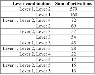
Table 3: The lever combinations most commonly used. Lever combination Sum of activations
Lever 1, Lever 2 579
Lever 1 160
Lever 1, Lever 2, Lever 4 72
Lever 2 69
Lever 2, Lever 3 57
Lever 3 54
Lever 1, Lever 3 45 Lever 1, Lever 2, Lever 3 28 Lever 2, Lever 4 22
Lever 4 17
Lever 1, Lever 2, Lever 5 15 Lever 1, Lever 5 13 5 CONCLUSION AND PERSPECTIVES
In this article, we defined processability items in semiconductor industry. We introduced the problem of the evolution of processability rules (fab constraints) considering the case of the 300mm production unit
of STMicroelectronics in Crolles. To overcome this problem, we defined a modeling approach that helps to identify the original signification behind fab constraints and to take into account the “real” user re-quirements. We defined a model that covers all the processability rules, respecting the strong requirement of easiness to adapt to changes. This model meets the flexibility characteristic to have a margin of "con-figurability" in processability rules, and agility characteristic needed to integrate any new processability item. The proposed approach was validated on industrial data. Finally, we believe that the proposed mod-el can be applied to other companies or used in similar contexts.
The proposed model will be detailed (in particular the UML class diagrams) in a next paper. This model is the cornerstone for further research activities to define a flexible and agile MES solution for semiconductor manufacturing. The general objective is to define models that can be shared among appli-cations from distinct processes and to ensure continuity of operations, system integrity, taking into ac-count the "real" user needs, and meeting evolution requirements.
ACKNOWLEDGMENTS
This work was supported by the French National Agency for Research and Technology (ANRT).The au-thors are grateful to Guillaume CHEZAUD and the Crolles300 IT team for their support.
REFERENCES
Avila, O., V. Goepp, F. Kiefer. 2010. “A method for the complete alignment of technical information systems”. In Proceedings of the 8th ENIM IFAC International conference of modeling and simulation: evaluation and optimization of innovative production systems of goods and services, 1010 – 1020. Hammamet, Tunisia.
Chapurlat, V., B. Kamsu-Foguema, F. Prunet. 2003. “Enterprise model verification and validation: an ap-proach”. Annual Reviews in Control 27:185–197.
Chen, R. S., C. M. Sun, M. M. Helms, W. J. K. Jih. 2008. “Aligning information technology and business strategy with a dynamic capabilities perspective: A longitudinal study of a Taiwanese Semiconductor Company”. International Journal of Information Management 28:366–378.
Chien, C.-F., S. Dauzère-Pérès, H. Ehm, J. W. Fowler, Z. Jiang, S. Krishnaswamy, T. Lee, L. Mönch, R. Uzsoy. 2011. “Modelling and analysis of semiconductor manufacturing in a shrinking world: chal-lenges and successes”. European Journal of Industrial Engineering 5:254-271.
Dauzère-Pérès, S., C. Yugma, S. C. Sarin. 2011. “Editorial: Novel models and approaches for semicon-ductor Manufacturing”. Production Planning and Control 22:1-3.
Fu, M., M. Haghnevis, R. Askin, J. Fowler, M. Zhang. 2010. “Machine qualification management for a semiconductor back-end facility” In Proceedings of the 2010 Winter Simulation Conference, Edited by B. Johansson, S. Jain, J. Montoya-Torres, J. Hugan, and E. Yücesan, 2486-2492.
Goepp, V., F. Kiefer, F. Geiskopf. 2006. “Design of information system architectures using a key-problem framework”. Computers in Industry 57: 189-200.
Henderson, J. C., N. Venkatraman. 1993. “Strategic alignment: leveraging information technology for transforming organizations” IBM Systems Journal 32:4-16.
Johnzén, C., S. Dauzère-Pérès, P. Vialletelle. 2011. “Flexibility measures for qualification management in wafer fabs”. Production Planning & Control 22:81-90.
Kabak, K.E., C. Heavey, V. Corbett, P.J. Byrne. 2013. “Impact of Recipe Restrictions on Photolithogra-phy Toolsets in an ASIC Fabrication Environment” IEEE Transactions on Semiconductor Manufac-turing 26:53-68.
Kiba, J. E., G. Lamiable, S. Dauzère-Pérès, C. Yugma. 2009. “Simulation of a full 300mm semiconductor manufacturing plant with material handling constraints”. In Proceedings of the 2009 Winter Simula-tion Conference, Edited by M. D. Rossetti, R. R. Hill, B. Johansson, A. Dunkin, and R. G. Ingalls, 1601 – 1609.
Mönch, L., J. W. Fowler, S. Dauzère-Pérès, S. J. Mason, O. Rose. 2011. “A survey of problems, solution techniques, and future challenges in scheduling semiconductor manufacturing operations”. Journal of Scheduling 14:583-599.
Ullah, A., R. Lai. 2013. “Requirements engineering and Business/IT alignment: Lessons Learned”. Jour-nal of Software 8:1-10.
Wu, M., Y. L. Huang, Y. C. Chang, K. F. Yang. 2006. “Dispatching in semiconductor fabs with machine-dedication features”. The International Journal of Advanced Manufacturing Technology 28:978-984.
AUTHOR BIOGRAPHIES
AHMED BEN AMIRA is a PhD student at EMSE. He is member of STMicroelectronics Crolles300. He received his Engineering and M.S. degrees in Industrial Engineering from Grenoble Institute of Technol-ogy, France, in 2011. His e-mail address is [email protected].
GUILLAUME LEPELLETIER is Senior Project Leader at STMicroelectronics. He receives a master of sciences in “Advanced Modelling Systems”, Brunel University, Uxbridge, UK, 1997; an Engineering de-gree in Operations and Production Management, INSA de Lyon, France, 1997. He has 14 years of profes-sional experience in Industrial Engineering in the semiconductor industry, working on Capacity Planning, Cycle Time Management, Discrete Event Simulation, Industrial Reporting and Equipment Performance Tracking. His mail address is [email protected].
PHILIPPE VIALLETELLE is Senior Principal Engineer at STMicroelectronics. After receiving an En-gineering degree in Physics, he entered the semiconductor industry working on ESD and physical charac-terization. Moving then to Metrology and Process Control where he drove the deployment of methodolo-gies and tools for a 200mm fab. His next experience was then Industrial Engineering with the deployment of several solutions for Equipment Performance Tracking, WIP management (dispatching and scheduling) Cycle Time management and Discrete Event Simulation. At European level, he is in charge of the defini-tion and follow-up of collaborative programs in the field of Manufacturing Sciences such as HYMNE, IMPROVE or INTEGRATE. His email address is [email protected].
STÉPHANE DAUZÈRE-PÉRÈS is Professor and Director of the Center of Microelectronics in Pro-vence of the EMSE. He received the Ph.D. degree from the Paul Sabatier University in Toulouse, France, in 1992; and the H.D.R. from the Pierre and Marie Curie University, Paris, France, in 1998. His research interests broadly include modeling and optimization of operations at various decision levels (from real-time to strategic) in manufacturing and logistics, with a special emphasis on semiconductor manufactur-ing. He has published 45 papers in international journals and contributed to more than 100 communica-tions in conferences. Stéphane Dauzère-Pérès has coordinated multiple academic and industrial research projects, and also five conferences. His email address is [email protected].
CLAUDE YUGMA is Associate Professor at EMSE. He received the Ph.D. degree from Grenoble Insti-tute of Technology, France, in 2003. His main work focuses on problems related to semiconductor manu-facturing sciences as scheduling, Advanced Process Control, etc.. His email address is [email protected]. PHILIPPE LALEVÉE is Associate Professor and Deputy Director of the Center of Microelectronics in Provence of the EMSE. He received his M.S. from National Institute of Telecommunications, and his Ph.D. in Computer Science from the Pierre et Marie Curie University of Paris, France, in 1995. His cur-rent research interests include EIS security and trusted communication networks. His email address is