HAL Id: hal-00664851
https://hal.archives-ouvertes.fr/hal-00664851
Submitted on 31 Jan 2012
HAL is a multi-disciplinary open access
archive for the deposit and dissemination of
sci-entific research documents, whether they are
pub-lished or not. The documents may come from
teaching and research institutions in France or
abroad, or from public or private research centers.
L’archive ouverte pluridisciplinaire HAL, est
destinée au dépôt et à la diffusion de documents
scientifiques de niveau recherche, publiés ou non,
émanant des établissements d’enseignement et de
recherche français ou étrangers, des laboratoires
publics ou privés.
From Object-Oriented Applications to
Component-Oriented Applications via
Component-Oriented Architecture
Simon Allier, Salah Sadou, Houari Sahraoui, Régis Fleurquin
To cite this version:
Simon Allier, Salah Sadou, Houari Sahraoui, Régis Fleurquin. From Object-Oriented Applications to
Component-Oriented Applications via Component-Oriented Architecture. 9th Working IEEE/IFIP
Conference on Software Architecture (WICSA’11), Jun 2011, Boulder, United States. pp.214-223.
�hal-00664851�
From Object-Oriented Applications to Component-Oriented Applications via
Component-Oriented Architecture
Simon Allier
Valoria lab. Universit´e de Bretagne Sud
Vannes, France [email protected]
Salah Sadou
Valoria lab. Universit´e de Bretagne Sud
Vannes, France [email protected] Houari Sahraoui DIRO Universit´e de Montr´eal Montreal, Canada [email protected] R´egis Fleurquin Valoria lab. Universit´e de Bretagne Sud
Vannes, France [email protected]
Abstract—Object-oriented applications of significant size are often complex and therefore costly to maintain. Indeed, they rely on the concept of class which has low granularity with var-ied dependencies not always explicit. The component paradigm provides a projection space well-structured and of highest level for a better understanding through abstract architectural views. But it is possible to go further. It may also be the ultimate target of a complete process of re engineering. The end-to-end automation of this process is a subject on which literature has made very little attention. In this paper, we propose such a method to automatically transform an object-oriented application in an operational component-oriented application. We illustrate this method on a real Java application which is transformed in an operational OSGi application.
Keywords-automatic reengineering; object oriented applica-tions; component-based architecture
I. INTRODUCTION
A system is complex and particularly difficult to under-stand and to maintain when it is described with a large number of highly interdependent parties. An object-oriented application is often complex because it uses hundreds or thousands of classes with many different dependencies more or less explicit. Conversely, the concept of component is deemed to provide modeling elements well suited to high-level representation, synthetic and well-organized structure of complex software. A component view tends to a descrip-tion characterized by a smaller number of parties loosely coupled, highly cohesive with clear inter-dependencies that are rigorously defined. Thus, the component paradigm can provide a ”space of projection” that simplifies the under-standing of a complex object-oriented system. It allows the construction of higher-level architectural views, simpler and more regular than those provided by an object-oriented system. Such views may facilitate the step of understanding a system prior to any activities of changing all or part of an object-oriented system.
In this case, the component-based architecture remains only a ”contemplative” view. It is used only by the designer but is not the entry point of further automatic processing. It is possible to use such a view in a more ”productive” way in the sense of Model Driven Engineering. One can
use this view as a blueprint to do a complete re-engineering including a source code translation: transforming an ational object-oriented application into an equivalent oper-ational component-based application. The new form of the application benefits from all the good properties associated with component-oriented paradigm. Indeed, the process of identifying a component is always guided by the rela-tionships between classes while meeting certain criteria: implementation of a specific functionality, optimization of a given structural metric, etc. Thus, the provided and required interfaces, corresponding to interactions between these sets of classes (discovered components), enforce some good structural properties in terms of coupling and cohesion.
To achieve this goal, we must solve two problems: i) iden-tifying classes that should be grouped to form abstract com-ponents and then constructing their required and provided interfaces. Thus we obtain a component-based architectural view of the application; ii) using this component-based architectural view to restructure the application into a new operational one, which conforms with a concrete component model. There are several works that partially deal with the first problem (a summary is given in Ducasse et al. [1]). In CBSE of the last year, we have also presented an approach that improves the identification of components in object-oriented applications [2]. Except works presented in [3], [4], none of the other works propose provided and required interfaces. So most of the existing works do not provide a complete architectural view. To the best of our knowledge, there is no work dealing with the second problem. What we propose in this paper is an approach to completely automate the process of transforming an operational object-oriented application into an operational component-based application: identify abstract components (groups of classes), extract their interfaces (architectural view) and finally, transform the application using a concrete component model (OSGi).
The remaining of the paper is organized as follows: Section II describes some related works. In Section III we describe our approach to obtain a component-based architecture of the object-oriented application. Our approach to restructure the operational object-oriented application into
an operational component-based application is describe in Section IV. Before concluding, we present a case study in Section V.
II. STATE OF ART
The complete re-engineering of object-oriented applica-tions into component-based applicaapplica-tions is not a trivial task. The first step is to identify the components by studying the clustering of the classes according to different criteria such as coupling and cohesion. Several works have focused on the problem of classes clustering with the aim of repackaging. A complete state of the art can be found in [1]). For example, the Bunch algorithm [5] extracts a high-level architecture by clustering modules (files in C or classes in C++ or Java) into subsystems based on module dependencies. This clustering is done using heuristic-search algorithms.
Some works specifically deal with components identifica-tion. For example, Kim et al. [6] propose a systematic UML-based method using, both functional and structural criteria, to identify the components. From use case, sequence or col-laboration diagrams, they measure the dependency between use cases. These dependencies are used to cluster the use cases in components. Then, dependency between classes, involved in the use cases, are used to check and refine the identified components. Also based on UML diagrams, Lee et al. [7] proposed a clustering algorithm that considers cohesion (functions supported by classes), class interaction (caused by method invocations) and class static coupling (caused by association, composition and inheritance). In the ROMANTIC method, Chandigny et al. [3] use an annealing clustering algorithm. The used fitness function is based on some quality characteristics (such as composability, maintenability, reliability, etc.) measured by existing metrics (such as complexity, class cohesion, etc.).
However all these approaches do not formally identify the provided and required interfaces of components. This is the second necessary step to build a complete component-based architecture. The FOCUS [4] approach proposes a light-weight method to architectural recovery of OO systems. This approach recovers components (clustering classes using relation-ships among them with respect of some rules) but also high level connectors. However, these connectors indicate only that there are some communications between two components. Thus, they remain too abstract in regard of a complete identification of required and provided interfaces. The third and final step consists in transforming the existing object-oriented application into a component-based application starting from the architectural view obtained previously. This step should lead to an executable version of the application in the target concrete component model. To the best of our knowledge, there is only one work that deals with this step: Washizaki et al. [8] propose a method that gives a set of candidate components, starting from the relations between classes, in the source code,
and a desired functionality represented by a given class. When a component is selected from the candidate ones, its corresponding set of classes is refactored into a JavaBean component. Thus, the aim is the extraction of reusable components. The use of this approach to automatically restructure an object-oriented application into a component-based application raises two main problems: Identify all the functionalities that the application covers, and assemble the extracted components to rebuild the application. If the first problem can be solved using the initial specifications of the application, the second problem remains a real challenge.
III. FROMOBJECT-ORIENTEDAPPLICATION TO
COMPONENT-BASEDARCHITECTURE
Two steps are necessary to produce an component-oriented architectural view from an object-component-oriented appli-cation: i) identify components, ii) identify the provided and required interfaces and to bind them together. We will examine each of these aspects in the following sub-sections.
A. Component Identification
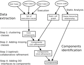
A component is a group of classes collaborating to provide a function of the application. Thus, to build a component-oriented view of all the application, we have to define a parti-tion of its classes. Each member of this partiparti-tion will become a component. To do so, we apply an extension of a method that we already presented in [2]. This method includes 3 steps (see Figure 1). In the first step, we use traces obtained by executing scenarios corresponding to application’s use cases to identify what we call ”core components”. We use an heuristic search to find a near-optimal solution. In the second step, we rely on a static call graph to add, in the core components, some application’s missing classes. Indeed, all classes of the application are not necessarily covered by the executions traces. This step uses the same heuristic search as the previous step. The last step is to manually refine the generated partition. In this step, the user benefits from some information provided by the tool on the generated solution.We will discuss each of these three steps in detail in the following subsections.
1) First step: Core component identification: A clustering algorithm allows to partition the classes of the application. Unfortunately, the number of possible partitions grows ex-ponentially with the number of application classes. Makes for exhaustive search, for the optimal solution, infeasible in most cases. Thus, we decided to use a meta-heuristic. It designates a computational method that optimizes a problem by iteratively trying to improve a candidate solution. The improvement is done thanks to a given measure of quality using a fitness function. Meta-heuristics make few or no assumptions about the problem being optimized and can tackle a very large spaces of candidate solutions. However, meta-heuristics do not guarantee that the optimal solution will be found.
Figure 1. The steps for component identification.
In our approach, the search for the space of all possible partitions is implemented using an hybrid search [9], which combines two different meta-heuristics: genetic algorithm (GA) [10] and simulated annealing (SA) [11]. GA and SA algorithms are two well-known heuristic search algorithms used in many software engineering works [12]. We will not discus theses in detail in this paper. GA is a global heuristic search that applies changes to multiple solutions and returns a solution that is near-optimal. We use a GA solution as the initial solution of a SA algorithm. SA algorithm performs a local search that explores the neighbourhood to refine the GA solution. In our cases, both SA and GA algorithms use the same data, solution representation (a partition of the classes) and fitness function.
The used data are execution traces. An execution trace is a tree where each node is the execution of a method and each edge is a call of a method. They are obtained by capturing the calls between instance of classes during the execution of a use case scenario. Every thread, created during the execution, produces an execution trace. The identification of core components from execution trace is relevant only if the execution traces cover the major part of the application functions. Therefore, to extract the traces, we apply all the recorded execution scenarios from the documentation. Execution traces capture a subset of the application classes and some of their dependencies. One of the advantages associated with the use of execution traces is getting a call graph simpler than a call graph built on the source code. Indeed, it only lists the dependencies observed and not the potential ones.
The used fitness function (Equation 1) evaluates the quality of a solution (a partition defining a set of core components) considering both the internal cohesion of com-ponents and the level of inter-component coupling of every component C. eval(A) = 1 |Cl| ∑ C∈A (evalComp(C) ∗ |C|) (1)
The function takes as input a solution A (a set of core components) and calculates the weighed average of the fitness of individual components. (Cl being the set of classes of the application covered by traces). The fitness of individual component (Equation 2) depends mostly on their cohesion unless the coupling level is too high, in which case the fitness score is heavily penalized. The used threshold cm corresponds to the average coupling of all the classes in the application. The cohesion and coupling are evaluated as follows:
evalComp(C) = {
evalCoh(C)/2 if evalCoupling(C) < cm evalCoh(C)/2 + 0.5 otherwise. (2)
• Internal cohesion: a good component should include
classes that interact with each other to provide a specific set of functionalities. Therefore, the strength of these interactions are what we call cohesion. The internal cohesion measure (evalCoh(C)) evaluates how close the different classes are in the execution traces.
• Coupling: One of the strengths of component-based
development is that its components are loosely coupled and can be combined to build applications. Therefore, the coupling of a component (evalCoupling(C)) is the number of its classes that are connected to classes from another component.
We have shown in [2] that this approach can lead to interesting architectures.
2) Second step: Adding the missing classes: At the end of the previous step, we get a partition of the classes covered by the execution traces. Thus, it is possible that some classes have been ignored. From a functional point of view, These classes have low contributions in the application function-alities. Consequently, we believe that they should have less influence on the final component-based architecture of the application. Therefore, we decided to consider them in a second round and only to refine the solution obtained in the first step. A class that is already present in a core component can not migrate to another component during this step. Each missing class must either be placed in an existing core components, or participate in the creation of a new one.
We use in this step the same meta-heuristics GA and SA. The search space is the same as in the previous step (the set of all the possible partitions) but with a strong additional constraint that no existing classes can migrate from one component to another. However, the used data are different. We use a static call graph (built using a type analysis algo-rithm) to identify all the (potential) dependencies between the missing classes and the existing ones. This call graph is a super-set of the previous dynamic call graph.
The fitness function of this step is still using the equa-tion 1, but it relies on a new funcequa-tion to evaluate each component (equation 3). This function is always based on cohesion and coupling, but uses the static dependencies. The cohesion of a component C is evaluated by evalCoh′(C):
the number of calls between the methods of the component’s classes. The coupling of a component C is evaluate by evalCoupling′(C): the number of calls between the
com-ponent’s classes and the other classes.
evalComp′
(C) = 1 − evalCoh ′
(C)
evalCoupling′(C) + evalCoh′(C) (3)
Equation 3 is somewhat different from equation 2 because we wanted to promote the complement of existing core components with the missing classes rather than create new core components. At the end of this step we obtain a partition of all the classes of the application.
3) Third step: refining the architecture: With the two previous steps, we automatically obtain a partition of all the classes of the application. However, a meta-heuristic can not guarantee obtaining the optimal solution. The obtained solu-tion is considered sufficiently close to the optimal. Moreover, thanks to the previous steps we have a lot of information about the solution: such as the score of each component (coupling, cohesion), the score of each class in its assigned component and the list of components to which it might belong to without significantly affecting the final score. Thus, a designer with good knowledge of the application, can significantly improve the solution, if she/he receives some recommendations derived from information on the solution. To this end, we added a step, called collaborative, where the designer can refine the solution thanks to some points raised by our system. For example, if a class is not cohesive with the classes of its component and strongly coupled with another component, our approach recommends to move this class from one component to another.
4) Object-Oriented Interfaces: To finalize the distribution of elements coming from the object-oriented application into the core components we need to situate the interfaces (object-oriented meaning). In the object-oriented approach, an interface corresponds to the common definition of a type that may be implemented by several classes. In our case, a type implemented by a class only makes sense in the component that contains this class. Indeed, the types shared by the components are those defined by their provided in-terfaces (see next sub-section). Thus, the inin-terfaces (object-oriented meaning) are placed in components that contain classes that need them. This implies that the same interface can be located in two different components.
B. Identifying Required and provided interfaces
In the first stage, we identified groups of classes working together to form components that provide high level features.
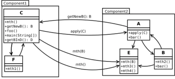
Figure 2. The application’s Call Graph.
However, in order to make an architectural view with these components, we need not only make their internal structure (classes and their relationships) invisible from the other components, but also provide them with provided and required interfaces to describe how they bind together. To build provided and required interfaces, we must first identify, respectively, provided and required services in order to organize them into consistent sets (interfaces).
1) Identifying component’s services: In our case, pro-vided and required services match to, respectively, incoming and outgoing method calls in respect with the component. Service identification is made from a system’s call graph (CG). A CG is a graph whose nodes represent the system’s methods and arcs represent calls between these methods. Provided services of a component correspond to all its methods (those defined in classes that it encompasses) that correspond to source nodes of arcs whose target node is in another component. Conversely, required services of a component corresponds to all its methods that correspond to target nodes of arcs whose source node is in another component.
As we said above, the identification of services uses a CG. But, there are two approaches to construct a CG:
• The first approach uses algorithms of type analysis. In
this case, the obtained CG is called static. It contains a superset of all possible calls but not those related to dynamic class loading nor dynamic method invocations. Indeed, these calls are impossible to determine stati-cally. Depending on the used type analysis algorithm, the CG will be more or less accurate (i.e. the super set of all possible calls will be more or less close to the set of all ”real” calls). For example, the Variable Type Analysis (VTA) algorithm [13] produce a more accurate CG than the Class Hierarchy Analysis algorithm [14]. VTA is a simple dataflow analysis that tracks, for each object reference (e.g., variable) in the program, the set of object types that it can contain. This information is used to further reduce the set of possible invocations at any given call site.
• The second approach uses execution traces. In this
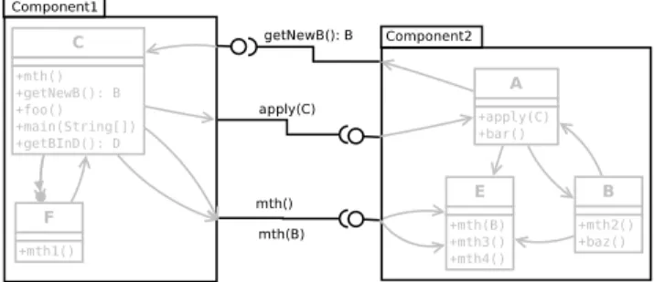
Figure 3. Component-oriented architecture of the application.
gives precise CG (calls have actually taken place) but perhaps not complete (it may lack of method calls). Moreover, such CG may contain calls due to dynamic class loading and dynamic method invocation.
The used CG, to extract the services, must be both accu-rate and as complete as possible. Indeed, if the CG contains too many calls, we’ll get noisy interfaces provided by un-necessary services (never used). Moreover, such a situation can lead to unnecessary dependencies between components. In contrast, if the CG is not complete, provided/required services could be omitted, which would lead to an inaccurate architecture of the application.
For these reasons, we built the CG as follows: First, we built a static CG using the VTA algorithm (which is sufficiently accurate). Then we completed It with the missing calls taken from a dynamic CG created using the execution traces that served for the step 1 of our process (see Figure 1). Thus we have a CG that combines the advantages of both approaches mentioned above. The analysis of this CG allows us to easily identify the required and provided services for each component. For example, in Figure 2 the set of provided services of component1 is:{C::getNewB(): B} and its set of required services is: {A::apply(C), E::mth(), E::mth(B)}.
2) Defining component’s interfaces: So far, thanks to CG, we have identified the required and provided services for each component. To obtain the required and provided interfaces of a component,we need to distribute its provided, respectively required, services into coherent subsets, in re-gards to of the application domain, to form these provided, respectively required, interfaces. As the application was built using the object paradigm, we use this same paradigm to identify these subsets.
We begin by identifying subsets representing provided in-terfaces for each component. For this, we gather in the same subset, provided services of a component, which come from the same class. Thus, the component provided interfaces will be as many as the number of its classes with methods needed from the outside (of the component). As shown in Figure 3, the number of services in a provided interface may be less than the number of methods of the class that supports
this provided interface. Thus, the provided interface, which is supported by the class C, contains only the service getNewB(). The other methods of this class will only be used by classes from the same component(Component1). The required interfaces of a component are constructed by analysing its needs. when a component requires at least one service from another component, we will construct a required interface, of the same type as the provided interface of the latter, concerned by this service. Thus, the component Component11 of figure 3 will have two required interfaces, corresponding to its needs of interfaces provided by the component Component2.
At this point, we obtained an architectural representation, based on the component paradigm, with the bare necessities of interactions between components in order to have an abstract view on the application (see again Figure 3). The aim of this abstract view is to simplify the understanding of the application in a maintenance stage.
IV. FROMCOMPONENT-BASEDARCHITECTURE TO
COMPONENT-ORIENTEDAPPLICATION
the previous step leads to the construction of a component-based architecture, of the object-oriented application, where components are represented by sets of classes with well identified provided and required interfaces. To restructure the operational object-oriented application into an operational component-based application, we will: i) use the object-oriented concepts, to implement the provided and required interfaces of the components; ii) map the identified com-ponents on a concrete component model. In this paper, we have chosen to show the mapping for the case of the OSGi component model.
A. Operational Interfaces
The previous step leads to an architecture composed with abstract components. The interfaces of these components are inferred elements which have no existence, as such, in the used object-oriented application. Threrefore, to make these components operational, we need to describe how their interfaces (required and provided) work with the classes they contain.
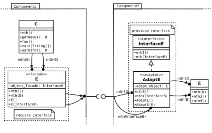
1) Making Provide Interfaces Operational: To be con-form with component paradigms, only the services present in the provided interfaces should be accessible from outside the component, and only through these interfaces. It is not wise to modify existing classes to achieve this goal. Indeed, the modification of existing classes can cause problems with their internal consistency. Thus, we decided to use the Adapter design pattern. This is illustrated through the figure 4. The provided interface InterfaceE, from component Component2, is implemented by the adapter adaptE. The latter serves as a relay to the class E that actually implements the services of the provided interface
Figure 4. Interface
interfaceE. The code, below, shows a little more pre-cisely the role of the adapter.
class AdaptE implements InterfaceE { private E adapt_object;
...
public void mth3(){ // delegation
adapt_object.mth3(); }
// manage shared objects
public void mth(InterfaceB ib){
B b = unWrapB(ib); adapt_object.mth3(b);
} }
The method mth receives, as a parameter, an object of type InterfaceB. In fact, in the object-oriented ap-plication, the parameter is of type B. No matter where stands the class B (Component2 in our example), the components only share objects of type defined by provided interfaces. Thus, before being passed as parameters, objects are wrapped into a type consistent with their corresponding provided interface (see next subsection). At the reception, as here in the method mth, objects are unwrapped in the correct type.
2) Satisfying Required Interfaces: In our case, when a component contains a required interface, it means that its classes need a class located in another component. Actually, they need only a subset of the methods from the needed class. This subset is represented by a provided interface in the component containing this class. To remain consistent with the component paradigm, and therefore, allow compo-nents to see only services that are visible through a provided interface of another component, we use the facade design pattern to represent a required interface. Thus, as shown in figure 4, each class is used by a component, but located in another, and replaced by a class of the same name that acts as a facade. The code of such a class is sketched below:
class E {
private InterfaceE facade_object; public E() {
facade_object = new AdaptE(); } public E(InterfaceE o) { facade_object = o; } public void mth3(){ facade_object.mth3(); } public void mth(B b){ InterfaceB ib = wrapB(b); facade_object.mth(ib); } }
The class E, in Component1, acts as a facade to ac-cess services provided by InterfaceE of component2. It keeps the same name (E) as the class located in Component2, in order to avoid modifications on classes of Component1, but it reduces the number of available methods to only those which are present in InterfaceE. Thus, it redirects calls through an object implementing InterfaceE. In addition, the facade class wraps objects, which must be passed as a parameter, in a type known by the other components (a corresponding provided interface). In the example above, this is achieved by wrapB() in the method mth().
The methods wrap() (facade object) and the method unwrap() (adapter object) together form a mechanism that ensures that only objects with a ”public” type (a type corresponding to a provided interface) can be exchanged between components. Moreover, classes that use objects of type E can also ask for creation. In this case, the constructor of the facade class (see the constructor E() above), which will be called by those classes, forwards the request of creation to the adapter of the right class E, which stands in another component (Component2).
B. Component Deployment
Once the object-oriented application is restructured into a component-based application, we need to reorganize it according to a concrete component model to make it op-erational. To illustrate this, we chose to use the OSGi com-ponent model [15]. Below we present the most important elements.
1) Creating the Bundles: In the OSGi framework, a component (called a bundle) is a set of classes organized into packages, which are by default not visible from outside the bundle. With the help of a manifest, it is possible to export packages. Classes and interfaces in these exported packages become visible from outside the bundle. Thus, they act as provided interfaces. Similarly, it is possible to indicate packages that the component requires to operate. Thus, classes and interfaces of these packages play the role of required interfaces.
In order to export the provided interfaces of our com-ponents, through the manifest, we placed them in specific packages. Similarly, the required interfaces are specified in the manifest by importing the packages containing them.
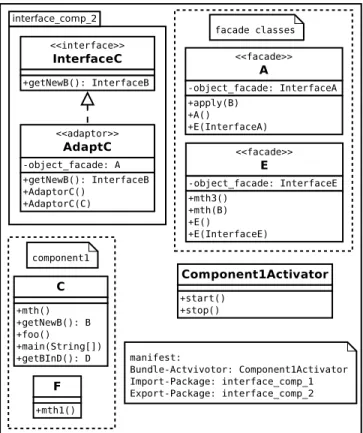
Figure 5. Example of a bundle
Indeed, then these are necessarily exported by other compo-nents.
For example, the bundle of figure 5 contains a pro-vided interface InterfaceC that is located in the pack-age interface_comp_2. Moreover, this bundle requires the interfaces InterfaceA and InterfaceE from the package interface_comp_1. All this is specified in the manifest as follow:
Import-Package: interface_comp_2 Export-Package: interface_comp_1
2) Management of the activators: Once the object-oriented application is restructured according to the con-crete component model, its launch must conform with the framework of this model. The OSGi framework al-lows the specification of actions to be performed dur-ing the different phases of the bundle’s lifecycle usdur-ing the class BundleActivator. We use this mechanism to launch the restructured applications. Thus, for each class containing an entry point (the main() method in Java), we create in its corresponding bundle a subclass of the class BundleActivator that redefines the method start(BundleContext). These subclasses are the po-tential activators of the bundle. The redefined method is only used to call the original entry point (main() method) of the application. Its parameter (BundleContext) contains, among others, the parameter of the main() method. Among
all the potential activators of a bundle, the designer should designate the actual one. It is identified in the fanifest as follows:
Bundle-Activator:
activator.Component1Activator
Finally, to build an OSGi bundle, the classes and the interfaces of a component, its activators (if any) and its manifest are archived in a jar file. For example, Fig-ure 5 shows Component1 structFig-ured as a bundle. This bundle consists of classes C and F, its unique provided interface (InterfaceC and its adapter AdaptC) and its facade classes (A and E). As this component has an entry point (main() method of class C), then the class Component1Activator was created and added to the bundle.
V. CASESTUDY
In this section we present a case study on an interpreter of the logo language written in Java. Logo is a language created for learning programming. The interpreter has a graphical interface which allows writing the code and a window which shows the result graphically. It contains 40 classes and 2 interfaces. The purpose of this study is to demonstrate the feasibility of our approach.
A. Used Tools
All the necessary tools for our approach have been implemented in Java using Soot [16] as an API. Soot is a popular Java static analysis framework. It provides call graph construction algorithms and an API that allows various operations on or from a Java byte code.
The implemented tools are:
• Tracer: This tool allows the generation of
execu-tion traces. Using Soot, cookies are injected into the bytecode of classes in order to trace method calls. Subsequently, the execution of use cases generate the desired traces.
• CBAExtracter: This tool allows to provide the
component-based architecture. It uses the traces, pro-vided by the Tracer, and a static call graph to produce the abstract components (sets of classes) of the appli-cation. The static call graph is used in a second time to take into account the missing classes, if any. Finally, it identifies the provided and required interfaces of the components in order to provide the component-based architecture.
• CBAToOSGi: This tool is used to implement the
com-ponent interfaces, then to organize each comcom-ponent as an OSGi bundle.
B. Process
The first step in our approach consists in obtaining the necessary data for identification of a the component-based
Figure 6. The Parsor component
architecture. For this, thanks to Tracer, cookies were injected into the classes of the Logo interpreter. Then, we executed scenarios corresponding to the 12 identified use cases. Ex-amples of use cases are “file creation/saving”, “code writing in the editor”, “code interpretation”, etc. We were given 26 execution traces (sequences of method calls) covering 38 classes of the interpreter. Two classes of the interpreter are not covered by these traces.
After that, the CBAExtracter is executed to build the component-based architecture. The latter builds a static call graph that allows on one hand to find dependencies of the missing classes, and on the other hand, to identify the component interfaces. The built static call graph contains 354 different method calls. The extracted component-based architecture is illustrated by Figure 7.
Let us look in more detail at the results of the different sub-steps (see Figure 2) necessary to obtain the component-based architecture of the Logo interpreter.
The first sub-step consists of obtaining cores components: We identified five of these. Four of these core components are made of highly cohesive sets of classes and there are few coupled with other components. In addition, each of these four components contains classes involved in the same functionality. For example, the first core component contains the necessary classes to parse and tokenize a sentence of the Logo language (see figure 6). The second core component consists of classes responsible for the output of the Logo language instructions.
Similarly 2 classes of the application are not covered by the traces, thus third sub-step is executed. These two classes are related to the errors management in parsing and evaluation. They are respectively added to the core components related to parsing and evaluation of Logo. This was done using the static CG.
In the manual refinement sub-step, of our process, the fifth component is highlighted for consideration. This component, consisting of two classes, was poorly evaluated by the fitness function. In fact, its classes have no special relationship between them, but are more coupled with other components.
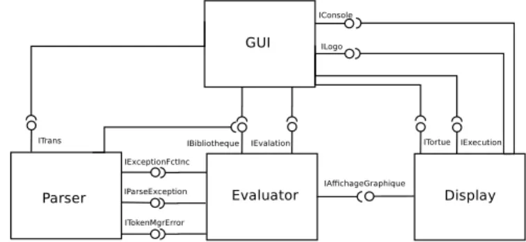
Figure 7. The component-based architecture of Logo interpreter
We decided to put its classes in the components to which they are most coupled. Thus, this component will no longer exist.
Then, the two interfaces of the application are added to components that have classes which implement them. This is done by the 4th sub-step. For example, the interface TransConstants is added to the first component (see Figure 6).
During the step of identifying interfaces, the components have been manually named according to their provided inter-faces. For example, the component of Figure 6 provides four interfaces: ITrans, ExceptionFctInconnue, textt-tIParseException and ITokenMgrError. The interface ITrans provides services for use of the Logo language parser. The 3 other interfaces provide services to manage the parse errors and these interfaces, all related to the parser, are mutually consistent. We call this component Parsor . The identification of provided interfaces of the component displayis an example of the need for a CG built using static and dynamic data. Indeed, in the class Evaluation of the component Evalaluator the method eval uses the dynamic method invocation to call the methods of the Logo interpreter which implements various functions of the Logo language. This is done as follows:
Object eval(List<Object> instr) { ... try { return ((Method)instr.get(1))).invoke(null,v,env); } ... }
With a type analysis (static analysis), it is impossible to determine the targets of the method invoke and thus the CG will be incomplete. However, the methods providing the graphical functions of Logo are implemented by the class AffichageGraphe of the component Display, and these methods are used by the class Evaluation. Thus, without dynamic calls obtained from the use cases we could identify the interface IAffichageGraphe .
Finally, the interfaces are instantiated and components are packaged in OSGi bundles. This is done automatically by following the approach described in Section IV.
VI. CONCLUSION
As we saw in the introduction of this paper, despite the use of object-oriented approach, the task of maintenance is always the biggest part of the overall cost of an application. Thus, reducing this cost is a real challenge. Furthermore, having an abstract view of an application greatly facilitates its understanding. Moreover, if the implementation of the application is easily mappable on this this view, then the achievement of the maintenance will be greatly facilitated. So, what we proposed in this paper allows : i) to build the abstract view of an object-oriented application as a component-based architecture. ii) to restructure the appli-cation according to this architecture. iii) and, to implement it according to a concrete component model.
The proposed solution is complete. Indeed, it restructures an operational object-oriented application into its equivalent operational component-oriented application. To our knowl-edge, this problem has never been treated as a whole. Thus, we tried to propose the more generic solutions to points listed above. The first two points are generic solutions: they are based only on general concepts of object and component approaches. So, the solution maybe applicable on any object-oriented language and any component model. The last point naturally depends on a particular object-oriented language and a concrete component model. We chose as an example, for this paper, the Java language and the OSGi framework, as a concrete component model, because they simplify the understanding. With the information contained by the built architecture, it seems pretty easy to map it to any other specific concrete component model.
We wanted a solution that is as possible automatic. But to achieve the most satisfactory solution, a collaboration with the designer is required. Thus, we have identified in the restructuring process the step that requires help from the designer. In this step the designer can have relevant information from the system in order to greatly improve the proposed solution. To illustrate our approach and show the process from beginning to end, we presented a real case study. We are behind the implementation of this case study, which allowed us to draw good conclusions.
However, the components extracted with our approach are influenced by the application on which they depend. We do not claim that they are reusable in any context. This is because the way to design of object-oriented applications is quite different from that for component-oriented appli-cations. As it was said by Lorenz “A good object-oriented
design does not necessarily make a good component-based design, and vice versa” [17].
Currently, the definition of component’s interfaces is based on existing classes. As future work, we want to capture more general semantics of a set of classes (component) to derive a better partitioning of services on the interfaces.
REFERENCES
[1] S. Ducasse and D. Pollet, “Software architecture reconstruc-tion: A process-oriented taxonomy,” IEEE Transactions on
Software Engineering, vol. 35, pp. 573–591, 2009.
[2] S. Allier, H. A. Sahraoui, S. Sadou, and S. Vaucher, “Restruc-turing object-oriented applications into component-oriented applications by using consistency with execution traces,” in
CBSE, 2010, pp. 216–231.
[3] S. Chardigny, A. Seriai, D. Tamzalit, and M. Oussalah, “Quality-driven extraction of a component-based aachitecture from an object-oriented system.” in CSMR, 2008, pp. 269– 273.
[4] N. Medvidovic and V. Jakobac, “Using software evolution to focus architectural recovery.” Automated Software Eng., vol. 13, no. 2, pp. 225–256, 2006.
[5] B. S. Mitchell and S. Mancoridis, “On the evaluation of the bunch search-based software modularization algorithm.” Soft
Comput., vol. 12, no. 1, pp. 77–93, 2008.
[6] S. D. Kim and S. H. Chang, “A systematic method to identify software components,” in APSEC. Washington, DC, USA: IEEE Computer Society, 2004, pp. 538–545.
[7] J. K. Lee, S. J. Seung, S. D. Kim, W. Hyun, and D. H. Han, “Component identification method with coupling and cohe-sion,” in APSEC. Washington, DC, USA: IEEE Computer Society, 2001, pp. 79–86.
[8] H. Washizaki and Y. Fukazawa, “A technique for auto-matic component extraction from object-oriented programs by refactoring.” Sci. Comput. Program., vol. 56, no. 1-2, pp. 99–116, 2005.
[9] V. Kelner, F. Capitanescu, O. L´eonard, and L. Wehenkel, “A hybrid optimization technique coupling an evolutionary and a local search algorithm,” J. Comput. Appl. Math., vol. 215, no. 2, pp. 448–456, 2008.
[10] J. Holland, Adaptation in natural and artificial systems. University of Michigan Press, 1975.
[11] N. Metropolis, A. W. Rosenbluth, M. N. Rosenbluth, A. H. Teller, and E. Teller, “Equation of state calculations by fast computing machines,” Journal of Chemical Physics, vol. 21, pp. 1087–1092, 1953.
[12] M. Harman, “The current state and future of search based software engineering,” in 2007 Future of Software
Engineering, ser. FOSE ’07. Washington, DC, USA: IEEE Computer Society, 2007, pp. 342–357. [Online]. Available: http://dx.doi.org/10.1109/FOSE.2007.29
[13] V. Sundaresan, L. Hendren, C. Razafimahefa, R. Vall´ee-Rai, P. Lam, E. Gagnon, and C. Godin, “Practical virtual method call resolution for java,” in OOPSLA ’00: Proceedings
of the 15th ACM SIGPLAN conference on Object-oriented programming, systems, languages, and applications. New York, NY, USA: ACM, 2000, pp. 264–280.
[14] J. Dean, D. Grove, and C. Chambers, “Optimization of object-oriented programs using static class hierarchy analysis,” in
ECOOP ’95: Proceedings of the 9th European Conference on Object-Oriented Programming. London, UK: Springer-Verlag, 1995, pp. 77–101.
[15] O. Alliance, “OSGi Service Platform, Core Specification, Re-lease 4, Version 4.2,” OSGI Alliance, Tech. Rep., September 2009.
[16] R. Vall´ee-Rai, E. Gagnon, L. J. Hendren, P. Lam, P. Pominville, and V. Sundaresan, “Optimizing Java bytecode using the Soot framework: Is it feasible?” in International
Conference on Compiler Construction (CC), 2000, pp. 18–34. [Online]. Available: www.sable.mcgill.ca/publications [17] D. Lorenz and J. Vlissides, “Designing components versus objects: a transformational approach,” in ICSE, May 2001, pp. 253–263.