an author's
http://oatao.univ-toulouse.fr/22984
https://doi.org/10.1016/j.compstruct.2018.10.081
Nasri, Monder and Garnier, Christian and Abbassi, Fethi and Labanieh, Ahmad Rashed and Dalverny, Olivier and
Zghal, Ali Hybrid approach for woven fabric modelling based on discrete hypoelastic behaviour and experimental
validation. (2019) Composite Structures, 209. 992-1004. ISSN 0263-8223
Hybrid approach for woven fabric modelling based on discrete hypoelastic
behaviour and experimental validation
M. Nasri
a,b,⁎, C. Garnier
a,⁎, F. Abbassi
c, A.R. Labanieh
d, O. Dalverny
a, A. Zghal
baUniversity of Toulouse, INP-ENIT/LGP, 47 Avenue d’Azereix, 65016 Tarbes, France bLMPE, ENSIT, University of Tunis, 5 Avenue Hussein, BP, 56, Bâb Manara, 1008, Tunisia cCollege of Engineering and Technology, American University of the Middle East, Kuwait dLaboratoire Génie et Matériaux Textiles (GEMTEX), ENSAIT, 95170 Roubaix, France
Keywords:
Hybrid discrete hypoelastic Non-linearity
Finite element analysis Bias extension test Woven fabric Composite forming
A B S T R A C T
A non-linear discrete hybrid approach based on the association of hypoelastic continuous elements (non-linear shear behaviour) with specific connectors (non-linear tension stiffness) is developed. It allows the simulation of a two-dimensional (2D) woven reinforcement forming via an accurate explicit finite element analysis. This ap-proach allows the simulation of 2D unbalanced fabrics uncoupling tensile and shear behaviour. It only needs a few parameters to be identified, and shows a good agreement with the experiments. The identification of the model parameters is investigated, and their relevance is analysed in reference tests. To determine the continuous element behaviour, a VUMAT hypoelastic model is implemented in Abaqus/Explicit. This model allows the prediction of fibre stresses and the accurate determination of shear angle in large deformations. Identification and validation of the model are performed using standard characterisation fabric tests. The experimental characterisation provided the numerical data to produce a representational prediction of the deformed fabric geometry and shear angle distribution. Further, the behaviour of the carbon woven reinforcement is identified. A bias extension test is used to both calibrate and validate the model. The capability of the model is illustrated to simulate deep drawing, and to compare with the experimental results of hemispherical forming.
1. Introduction
For several decades, composite materials have been increasingly used in many sectors, such as aeronautics where composites are already used on a large scale. The latest generation of airliners are made with more than 50% mass of composites[1]. Achieving a lightweight pro-duct and saving energy are the main challenges in the aircraft industry production, which explains the increase in composite demand and the diversity of its applications [2]. Several forming processes of woven composites are classified under different categories. The liquid com-posite moulding process involves forming of dry materials into shapes without resin (an example of such a process is the resin transfer moulding [3–5]). In this process, dry woven reinforcements are first formed, then the resin is injected to obtain the final shape[6,7]. This method has several disadvantages according to different points of view: difficulty of controlling the final shape and the effective mechanical properties, high cost of implementation, and low production rate. Some other problems are related to preform deformation draping: tension fibres between longitudinal and transverse direction, fibre
disorientation, and wrinkling or local buckling[8]. Knowledge about the process and accurate modelling are essential for the analysis of composite structures in service[8]. Numerical approaches for model-ling the forming of woven fabric composite reinforcement belong to two main categories that are related to the scale at which the analysis is made [9]. These approaches have several objectives with different impacts. First, it makes possible the determination of the feasibility, or the conditions of this possibility. Second, it allows predicting the po-sition of fibres after forming[8,10]. The literature proposes several approaches for modelling the behaviour of woven fabrics. For example, draping of the woven reinforcements can be achieved either by metric, continuous, discrete, or semi-discrete approaches. These geo-metric models involve placing a net on a surface along geodetic lines
[11]. This approach is based on the work of Mark and Taylor[12]with certain simplifying assumptions (Inextensibility of yarns, no sliding at the intersections of warps and wefts, free spins between the warps and wefts and non-slip contact between woven reinforcement and draping tool)[13]. This method is simple and although temporally very inter-esting for predicting the orientation of the yarns, but does not take into ⁎Corresponding authors at: University of Toulouse, INP-ENIT/LGP, 47 Avenue d’Azereix, 65016 Tarbes, France.
E-mail addresses:[email protected](M. Nasri),[email protected](C. Garnier).
account the physical properties of yarns in the warp and weft direc-tions. Thus, the result obtained is independent of the material used. This method is suitable for draping, but not for drawing processes, where a poor match with the experimental results had been observed
[14]. This model also decouples the tension and shear behaviours[10]. The continuous approach considers the woven fabric as a macro-scopically contained material, because it takes into account the homogenised overall behaviour of the reinforcement. The geometry of the reinforcement is illustrated by a finite element mesh of shell or membrane [15]. Three continuous approaches are described using a membrane and shell assumption.
(i) The first one is based on a continuous non-orthogonal elastic law. This approach involves formulating the constitutive law by linking the stress and strain through a continuous medium in a non-or-thogonal basis described in the directions of the reinforcing yarns because of the small influence of the shear angle on the biaxial behaviour[16]. Pu Xue et al. developed a model that indicates the behaviour of the woven composite using a non-orthogonal co-ordinate system[17].
(ii) The second approach is the continuous hypoelastic one. In this case, the stress increments are directly related to the strain incre-ments with a constitutive tensor containing the material stiffness moduli[18]. The main advantage is the representation of the non-linear behaviour and it is often implemented in finite element analyses at large strains. Several studies developed the hypoelastic laws for fabric reinforcement simulation [19–21]and for woven structures[22].
(iii) The third approach is the hyperelastic continuous model, which is also based on the decoupling between tension and shear. It relies on the definition of an energy potential from which the hyper-elastic constitutive model is derived and which reproduces the non-linear mechanical behaviour of fibrous reinforcements[9,23]. This potential is defined as the sum of three terms: the deformation energies in the two yarn directions and the shear behaviour. Ai-mene et al. [24]proposed a model of anisotropic hyperelastic behaviour for the simulation of woven fibrous reinforcements, which is likely to reproduce the non-linear behaviour observed on these woven reinforcements. The work presented by Erchiqui et al.
[25]demonstrates that this approach is able to predict the influ-ence of fibre orientation in the thermoforming process.
Furthermore, numerical modelling using the discrete approach re-presents the reinforcement as an elementary physical cell, which uses finite elements of bars, beams, membranes, or shells[26,27]. The ad-vantage of this approach is that it can justify certain global behaviour of tissues from its internal structure. In several publications, it is shown
that the advantage of this reinforcement method to simulate forming problems[28–30]. Boubaker et al.[31]proposed a model of woven reinforcements based on a mass–spring system. In[32], Sharma et al. proposed a model based on an elementary cell constructed only with elastic bars on the sides and an elastoplastic bar positioned according to one of the diagonals to model the non-linear shear behaviour. In 2010, the discrete modelling is still applied by Sherwood et al.[33], who used this approach to model two types of fabrics (glass taffeta and 2 × 2 twill). The discrete approach was also used by Najjar[34]to simulate the stamping process of an interlock reinforcement type G1151. The tension stiffness was modelled by connectors and the shear behaviour was modelled as elastic. In 2011, Harrison[35]proposed a behaviour model by combining a non-orthogonal approach to manage shear in a shell element, and bars to describe the behaviour of yarns in tension.
The semi-discrete approach is a combination of the continuous and discrete approach. It is a mesoscopic approach of an elementary re-inforcement cell using the finite element method. This approach is based on the virtual work theorem, which links internal, external, and acceleration works in the virtual displacement field[36].
In this present work, a hybrid discrete hypoelastic model is devel-oped, and then compared with experimental results. To determine the behaviour of HexForce 48600 C 1300 carbon fabric during the pre-forming process, some basic mechanical tests should be conducted. Tensile testing campaigns, up to the warp and weft directions of 48600 C 1300 carbon fabric, were carried out to determine the rigidity of the fabric, which is itself introduced in the numerical simulation. The fol-lowing aspects are presented in this paper:
•
Material characterisation and determination of the model para-meters,•
Formulation description of the hypoelastic and hybrid model,•
Identification of non-linear stiffness and shear,•
Validation of the shear and stress response on a single mesh and the bias extension simulation by comparing with marker tracking method data,•
Simulation of a hemispherical forming test,•
Comparison between the hemispherical forming test and numerical results.2. Materials and experimental investigations
2.1. Specimen and material used
To determine the behaviour of woven carbon reinforcements, ten-sile and bias extension tests were carried out following three directions (0°, 45°, and 90°), using 270 mm × 50 mm samples with a 150 mm gauge length. In this work, the carbon fabric used is HexForce 48600 C Nomenclature
Vector gradient Cauchy stress tensor
Objective derivative of Cauchy stress tensor
New Updated stress tensor
GN1,2 Green–Naghdi basis
GN1,20 Initial Green–Naghdi basis
F1,20 Initial material basis
F1,2 Material basis
F Deformation gradient tensor
R Rotation tensor
U Right stretch tensor
C Constitutive tensor
D Strain rate tensor
E11 Young’s Modulus in warp direction
E22 Young’s Modulus in weft direction
G12 In-plane shear rigidity
T1,2 Transformation matrix
dF1,2 Strain increments
d1,2 Stress increments
Shear angle
1,2 Angle between warp or weft and Green–Naghdi basis
Fb Normal bias force
F ( )sh Normalised shear force
Fc Connector force
Uc Connector displacement
e Thickness
K u( ) Connector stiffness
N Number of connectors in direction Y
The method of accounting for this non-linear behaviour involves defining a displacement interval. The polynomial coefficients in a va-lidity interval [0 mm, 3.9 mm] was determined from the experimental trend curve. The total behaviour of the specimen is written in the fol-lowing form:
= + +
Ft 170.85·ut4 573·ut3 123.13·ut2 19.75·ut 3.446 (4)
2.4.2. Bias extension test
The resulting load–displacement curves for the bias extension test are shown inFig. 5.
The experimental shear angle is then calculated and compared to the kinematic angle (Fig. 6), which was explained in the previous sec-tion. Experimental and kinematic shear angles correlate well up to 21° and then, the kinematic method overestimates the load observed from the test. The large clamp displacement and smaller shear angles, as shown by the experimental data, could be due to the appearance of yarn sliding. Actually, this phenomenon is commonly observed during bias
extension testing [43,44]. The occurrence of sliding at the interface between the zones makes it possible to stop the increase of shear in the central zone[20].
To validate the theory of three shear areas, the mark tracking method is used to calculate the shear angles in zones A, B, and C, as shownFig. 2. The calculation is done in the lower and upper part of the sample to sure that the deformation is symmetric. For a displacement value from 0 mm to 15 mm, both shear angles in the lower and upper part and for each area A, B and C are equivalent. It also can be noted that the shear angles in area A (supposed to be unsheared) is not equal to 0°. Furthermore, for a displacement of 15 mm, the average shear angle in zone B, supposed to be in pure shear, is equal to 20°, whereas in zone C, supposed to be half sheared, the average shear angle is ap-proximately 8°. The verification of the domain of validity of the kine-matic hypothesis, in which the shear angle in the half-sheared zone C is half the value of the one in the central zone (pure shear), is followed. However, the two zones A near the tabs, supposed to be unsheared, show a slight shearing (Fig. 7).
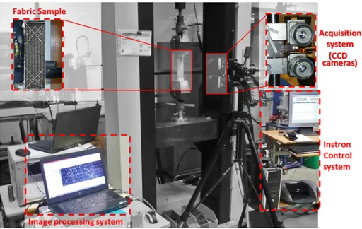
Fig. 1. Experimental setup for uniaxial tension and bias extension tests.
= = = = =
T T T
T T with T T T and T
[ ]2 1 cos ; sin ; sin cos .
2 22 32 42 1 2 2 22 2 32 2 42 2 (21) Then, the in-plane shear angle is defined as the change in the angle between the warp and weft yarns and specifically, here, it is defined by Eq.(2)in the bias test. Next, the constitutive law C[ ]( , )F F1 2, can be ap-plied for each warp and weft fibre directions and solved for incremental stress in the fibre frames using
= = d C d d C d [ ]F1 [ ] [ ] and [ ]F1 F1 F2 [ ] [ ]F2 F2 (22) where = = C E G C E G [ ] 0 0 0 0 0 0 0 and [ ] 0 0 0 0 0 0 0 . F F 11 12 22 12 1 2 (23) Here, (E11,E22) andG12 are the elastic tensile modulus and the in-plane shear modulus. The hypoelastic model has been implemented in a VUMAT user subroutine in Abaqus/Explicit.
The increments of the constraints are then cumulated according to the classical formulation of Hughes and Winget[48]:
= + = + = + + + + + + + + d d d d ( ) ( ) ( ) ( ) ( ) ( ) ( ) ( ) ( ) F n F n F n F n F n F n n n F F n 11 1 11 11 22 1 222 22 12 1 12 12 12 12 1 1 1 12 2 2 12 1 2 12
Finally, the stresses in the two directions of the fibres are calculated and then projected into the GN base by the transformation
= + + T T T T ( GN n) [ ][ ] [ ] [ ][ ] [ ] GN F T GNF T 1 1 1 1 2 2 2 (24)
3.4. Validation of continuous elements according to elementary tests
For the validation of the hypoelastic model applied to continuous elements, we carried out a comparative study with the results of Khan
[51]on a 3D quadrilateral membrane element with reduced integration (M3D4R). Three elementary tests were carried out on a single 1 × 1 mm element with bidirectional fibres: (i) 45° simple shear test, (ii) traction followed by 45° simple shear, and (iii) traction followed by rigid body rotation[51].
For the three cases, the elongation is twice the length of the element
=
(
ll 2)
0 , the thickness of the membrane is 1 mm, the tensile rigidity Ei for both directions (i = 1, 2) is 34 500 MPa, and there is no shear ri-gidity.
Strains after extension in the first direction (ε1), the final shear angle (γf), and the final stresses are extracted from the numerical simulation (Table 2) and compared to Khan’s results[51].
Three elementary tests were performed and found to have a good agreement with the literature. First, it is observed that the shear angle for tests 1 and 2 are 45°, whereas for test 3, it is 0°. These results are consistent with the physical deformation of the fabric. For a simple shear test, the shear angle is 45°, and for a rigid rotation it is 0°. Therefore, the unit cell is well deformed for the shear test whereas for rigid rotation, it is not. Second, it is observed that for a simple tension test (tests 2 and 3) in the fibre direction, the strain output is 0.69, which corresponds to the large strain theory. Third, it is observed that the stresses for simple shear computed for directions 1 and 2 are not equal to zero. Direction 2 is constrained (no displacement in direction 2 is allowed), which implies stresses in both directions. The values of the stresses are equivalent to Khan’s value. For the tensile step (test 3), only the fibres in direction 1 are deformed. The stress in direction 1 is 2.45E + 04 MPa, whereas in direction 2 it is 0 MPa.
Elementary tests allow the calculation of stresses, strains, and shear angles of a hypoelastic deformed fabric. The tension stresses obtained correspond exactly to the expected solutions in the case of a law linking
the Cauchy constraints and the logarithmic deformations. This ap-proach permits the calculation of the real characteristic, and the mag-nitudes of the output are equal to those in the literature. It describes well the behaviour in tension and there is no tension related to the rotation of rigid body. This approach is for rigid body rotations.
3.5. Validation of the hybrid discrete method according to elementary tests
In order to validate the hybrid discrete method, simple shear ele-mentary test is carried out on a 1 × 1 mm unit cell with a 1 mm thickness with 4 connectors. The difference with the validation of continuous element is that the membrane has no shear rigidity and has very low tensile rigidities: E1and E2are equal to 3.9 MPa. The tensile rigidity is modelled by a linear connector stiffness equal to 12 250 MPa. The output results are presented inTable 3. The computed shear angle is equal to 45° and the computed stresses are 2.45E + 04 MPa and 1.23E + 04 MPa for direction 1 and direction 2, respectively. By com-paring with the previous elementary tests on a hypoelastic continuous cell only, both approaches provide the same result qualitatively and quantitatively, validating the hybrid discrete hypoelastic approach on an elementary application.
3.6. Identification of the shear behaviour parameters
The material parameters of the continuous elements are the Young modulus, thickness, and in-plane shear rigidity (E, e, and G12 respec-tively). Our fabric is considered to be balanced (E11= E22). Finite element analyses of the bias-extension test are performed within an optimisation loop in order to determine the characteristics of the membrane elements. The identification of the parameters is then car-ried out using the inverse method by comparing the force–displacement curve obtained from the maximum loading test. The maximum shear angle is determined by the angle between two connectors, each char-acterising a yarn direction. Two variants of this model have been tested. The first model is a hybrid hypoelastic behaviour of the shell with the in-plane shear rigidity G12considered constant. The second one, with a non-linear shear modulus G, has been determined inSection 2.
The bias extension test parameters used for the numerical bias test are presented inTable 4.
Fig. 13shows that the hypoelastic discrete hybrid model followed the woven fabric behaviour up to the displacement of 21 mm, which corresponds to the beginning of the appearance of sliding in the bias tests. From this value, the two numerical and experimental curves di-verge. Another numerical simulation of the bias extension test was carried out using the discrete hypoelastic hybrid model, where the shear modulus is not constant. This study made it possible to demon-strate the different shear zones according to the literature. A compar-ison between the experimental and numerical values (normalised load and shear angle) presented inFig. 14shows that they are in perfect agreement before the sliding begins and when reaching the locking
Table 2
Computed results for elementary tests on continuous element.
Test no. 1 γf(°) Computed stress tensor
= f MPa 11 22 12
Khan’s stress tensor[51]
= fK MPa 11 22 12 1 45 = 1.23E0+04 0 f = E+ 0 1.23 04 0 fK 2 0.69 45 = ++ E E 2.45 04 1.23 04 0 f = + + E E 2.45 04 1.23 04 0 fK 3 0.69 0 = 2.45E0+04 0 f = + E 2.45 04 0 0 fK
6. Conclusions
In this study, both experimental and numerical investigations were carried out. The methodology and the numerical model developed in this study allow the forming of dry woven fabrics. The main aim is to propose a simulation uncoupling the shear behaviour and tensile be-haviour of the fabric. This simulation was developed via a linear con-nector element for the tensile behaviour and continuous membrane element for the shear behaviour. To obtain a more accurate model, a non-linear trend behaviour was used for tension and shear, and a hy-poelastic behaviour was used to follow the rotation of the fibre during forming. With this discrete hypoelastic model, shear angles and locking angles are predicted and can be used for designing complex parts without generating defects.
First, the experimental study allows the characterisation of the fabric in tension and shear by using the mark tracking method during tensile tests and bias extension tests. Second, a methodology was de-veloped to identify, from previous tests, the non-linear behaviour of the fabric. Two 4th order polynomial equations were identified to model the non-linear stiffness of the connector and the non-linear shear ri-gidity of the membrane element. Third, a highly accurate numerical model was developed to analyse the fabric deformation. This model involved the assembly of the non-linear tension behaviour of a linear connector element with the non-linear shear behaviour of a hypoelastic membrane element. This model was validated with some elementary tests found in the literature. A numerical model of the fabric forming process using a hemispherical punch was presented in the last section of
this paper. It provided numerical results that were close to the experi-mental ones. Thus, the model was also validated in a more complex way.
The non-linear hypoelastic discrete model was developed for ma-terials having two orthogonal directions of strong anisotropy. This model was able to predict fibre stresses and to determine, with high precision, the shear angles based on the modification of the orientation of the wires in large deformation. It was validated in different config-urations, showing its ability to describe the composite behaviour and the high accuracy of shear angle prediction. Moreover, the proposed approach can be used to model the behaviour of pre-impregnated fab-rics with unbalanced fabfab-rics.
Acknowledgements
The authors acknowledged that this work relies jointly on the skills and material resources of these entities: UMSSTT-ENSIT, Tunisia and LGP at ENI de Tarbes, France for the experimental methods and nu-merical modelling. This work also benefits from the support of Nimitech Innovation Company.
References
[1] Abbassi F, et al. Experimental and numerical investigations of a thermoplastic composite (carbon/PPS) thermoforming. Struct Control Health Monit 2011;18(7):769–80.
[2] Ahmad F, et al. Numerical investigation to evaluate effect of fiber orientation on
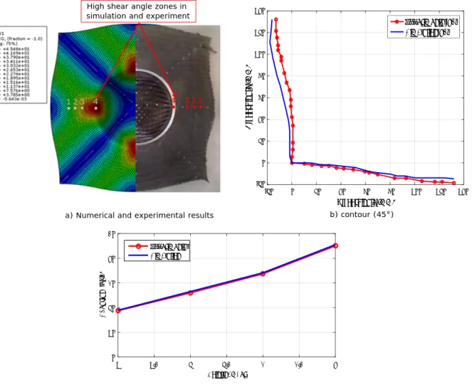
a) Numerical and experimental results b) contour (45°) High shear angle zones in
simulation and experiment
-20 0 20 40 60 80 100 120 140 X coordinate (mm) -20 0 20 40 60 80 100 120 140 Y coordinate (mm) 1 1.5 2 2.5 3 3.5 4 Point number 0 10 20 30 40 50 Shear angle (°) Experimental Simulation
c) comparison between numerical and experimental shear angle
Experimental 45° Simulation 45°
Fig. 16. Numerical and experimental results of dome forming with 45°/−45° initial orientations of tows: a) shear angle, b) contour, and c) comparison between
penetration-resistance of an aircraft composite material. Mech Adv Mater Struct 2018:1–9.
[3] Kim PJ, Lee DG. Surface quality and shrinkage of the composite bus housing panel manufactured by RTM. Compos Struct 2002;57(1):211–20.
[4] Han SH, et al. Study on high-speed RTM to reduce the impregnation time of carbon/ epoxy composites. Compos Struct 2015;119(Supplement C):50–8.
[5] Garnier C, Mistou S, Pantale O. Influence of process and material parameters on impact response in composite structure: methodology using design of experiments. Key Eng Mater 2010;446:83–90.
[6] Launay J, Duong AV, Hivet G, Valle V, Allaoui S. La mesure des déformations pour l'étude du comportement et la mise en forme des renforts de composites. 18ème Congrès Français de Mécanique. 2007. Grenoble.
[7] Soulat D, Allaoui S, Chatel S. Experimental device for the preforming step of the RTM process. Int J Mater Form 2009;2(1):181–4.
[8] Boisse P, Borr M, Buet K, Cherouat A. Finite element simulations of textile com-posite forming including the biaxial fabric behaviour. Compos B Eng 1997;28(4):453–64.
[9] Boisse P, Aimène Y, Dogui A, Dridi S, Gatouillat S, Hamila N, et al. Hypoelastic, hyperelastic, discrete and semi-discrete approaches for textile composite re-inforcement forming. Int J Mater Form 2010;3(2):1229–40.
[10] Hamila N. Simulation de la mise en forme des renforts composites mono et multi plis. 2007.
[11] Van Der Weeën F. Algorithms for draping fabrics on doubly-curved surfaces. Int J Numer Meth Eng 1991;31(7):1415–26.
[12] Lim T-C, Ramakrishna S. Modelling of composite sheet forming: a review. Compos A: Appl Sci Manuf 2002;33(4):515–37.
[13] Hamila N, Boisse P. A meso-macro three node finite element for draping of textile composite preforms. Appl Compos Mater 2007;14(4):235–50.
[14] Vanclooster K, Lomov Stepan Vladimirovitch, Verpoest Et, Ignace VANCLOOSTER, Kristof LOMOV. Stepan Vladimirovitch, et VERPOEST, Ignace. Experimental vali-dation of forming simulations of fabric reinforced polymers using an unsymmetrical mould configuration. Compos A Appl Sci Manuf 2009;40(4):530–9.
[15] Dong L, Lekakou C, Bader MG. Processing of composites: simulations of the draping of fabrics with updated material behaviour law. J Compos Mater
2001;35(2):138–63.
[16] Buet-Gautier K, Boisse P. Experimental analysis and modeling of biaxial mechanical behavior of woven composite reinforcements. Exp Mech 2001;41(3):260–9. [17] Pu Xue XP, Cao Jian. A non-orthogonal constitutive model for characterizing woven
composites. Compos A 2003;34:183–93.
[18] Bernstein B. Hypo-elasticity and elasticity. Arch Ration Mech Anal 1960;6(1):89–104.
[19] Hagège B, Boisse P, Billoët J-L. Finite element analyses of knitted composite re-inforcement at large strain. Revue Européenne des Éléments Finis
2005;14(6–7):767–76.
[20] De Luycker E, et al. Simulation of 3D interlock composite preforming. Compos Struct 2009;88(4):615–23.
[21] Belytschko T, Liu WK, Moran B, Elkhodary K. Nonlinear Finite Elements for Continua and Structures. John Wiley & Sons; 2013.
[22] Khan MA, et al. A parametric sensitivity study on preforming simulations of woven composites using a hypoelastic computational model. J Reinf Plast Compos 2015;35(3):243–57.
[23] Ten Thije RHW, Akkerman R, Huétink J. Large deformation simulation of aniso-tropic material using an updated Lagrangian finite element method. Comput Meth Appl Mech Eng 2007;196(33–34):3141–50.
[24] Aimène Y, et al. A hyperelastic approach for composite reinforcement large de-formation analysis. J Compos Mater 2009;44(1):5–26.
[25] Erchiqui F, Gakwaya A. Analysis of long fibers direction of transversely isotropic hyperelastic material for thermoforming application. J Reinf Plast Compos 2005:24(9).
[26] Erol O, Powers BM, Keefe M. A macroscopic material model for woven fabrics based on mesoscopic sawtooth unit cell. Compos Struct 2017;180(Supplement C):531–41. [27] Cavallaro PV, Johnson ME, Sadegh AM. Mechanics of plawoven fabrics for
in-flated structures. Compos Struct 2003;61(4):375–93.
[28] Cherouat A, Billoët JL. Mechanical and numerical modelling of composite
[29] Cherouat A, Billoët JL. Finite element model for the simulation of preimpregnated woven fabric by deep-drawing and laying-up processes. J Adv Mater
2000;32(4):42–53.
[30] Sidhu RMJS, Averill RC, Riaz M, Pourboghrat F. Finite element analysis of textile composite preform stamping. Compos Struct 2001;52(3):483–97.
[31] Boubaker BB, Haussy Bernard, Ganghoffer Et, Jean-François. Discrete models of fabric accounting for yarn interactions: simulations of uniaxial and biaxial beha-viour. Revue Européenne des Eléments 2005;14(6–7):653–75.
[32] Sharma SB, Sutcliffe MPF. A simplified finite element model for draping of woven material. Compos A Appl Sci Manuf 2004;35(6):637–43.
[33] Jauffrès D, Sherwood JA, Morris CD, Chen J. Discrete mesoscopic modeling for the simulation of woven-fabric reinforcement forming. Int J Mater Form
2010;3(2):1205–16.
[34] Najjar W, Legrand X, Cedric P, Soulat D, Boude S. A simple discrete method for the simulation of the preforming of woven fabric reinforcement. Key Eng Mater 2012. 504–506: p. 213–218.
[35] Harrison P, Woong-Ryeol, et LONG YU, Andrew C. Rate dependent modelling of the forming behaviour of viscous textile composites. Compos A Appl Sci Manuf 2011;42(11):1719–2172.
[36] Wang P, Hamila N, Boisse P. Prédiction par simulation des défauts de plissement lors de la mise en forme des matériaux composites mono et multiplis. Matériaux & Techniques 2012;100(6–7):591–9.
[37] Hexcel, Hexflow® 48600 C 1300, in Fiche technique2015.
[38] Misnon MI, et al. Analyses of woven hemp fabric characteristics for composite re-inforcement. Mater Des 2015;66:82–92.
[39] Gherissi A, et al. Numerical and experimental investigations on deep drawing of G1151 carbon fiber woven composites. Appl Compos Mater 2016;23(3):461–76. [40] Erol O, Powers B, Keefe M. Development of a non-orthogonal macroscale material
model for advanced woven fabrics based on mesoscale structure. Compos B Eng 2017;110:497–510.
[41] Boisse P, Hamila N, Guzman-Maldonado E, Madeo A, Hivet G, Dell’Isola F. The bias-extension test for the analysis of in-plane shear properties of textile composite re-inforcements and prepregs: a review. Int J Mater Form 2017;10(4):473–92. [42] Goidescu C, Welemane H, Garnier C, Fazzini M, Brault R, Péronnet E, et al. Damage
investigation in CFRP composites usingfull-field measurement techniques: combi-nation of digitalimage stereo-correlation, infrared thermography andX-ray tomo-graphy. Compos B Eng 2013;48:95–105.
[43] Harrison P, Clifford MJ, Long AC. Shear characterisation of viscous woven textile composites: a comparison between picture frame and bias extension experiments. Compos Sci Technol 2004;64(10):1453–65.
[44] Creech G, Pickett AK. Meso-modelling of non-crimp fabric composites for coupled drape and failure analysis. J Mater Sci 2006;41(20):6725–36.
[45] Cao J, Akkerman R, Boisse P, Chen J, Cheng HS, De Graaf EF, et al. Characterization of mechanical behavior of woven fabrics: experimental methods and benchmark results. Appl Sci Manuf Compos A 2008.
[46] Dumont, F., Expérimentations et modèles de comportement de renforts de com-posites tissés, 2003.
[47] Boisse P, Cherouat A, Gelin JC, Sabhi H. Experimental study and finite element simulation of a glass fiber fabric shaping process. Polym Compos 1995;16(1):83–95. [48] Hughes TJ, Winget J. Finite rotation effects in numerical integration of rate
con-stitutive equations arising in large-deformation analysis. Int J Numer Meth Eng 1980;15(12):1862–7.
[49] Hagege, Simulation du comportement mécanique des milieux fibreux en grandes transformations: application aux renforts tricotés, 2004.
[50] Saint-Marc JC, Gakwaya A. Development of a Ballistic Hybrid Fabric Model for Aeroengine fan Blade Containment Application. 2012.
[51] Khan MA, Numerical and experimental forming analyses of textile composite re-inforcements based on a hypoelastic behaviour 2009–2010.
[52] Labanieh AR, Garnier C, Ouagne P, Dalverny O, Soulat D. Intra-ply yarn sliding defect in hemisphere preforming of a woven preform. Appl Sci Manuf Compos A 2018.
manufacturing processes deep-drawing and laying-up of thin pre-impregnated woven fabrics. J Mater Process Technol 2001;118(1):460–71.