Open Archive TOULOUSE Archive Ouverte (OATAO)
OATAO is an open access repository that collects the work of Toulouse researchers and
makes it freely available over the web where possible.
This is an author-deposited version published in :
http://oatao.univ-toulouse.fr/
Eprints ID : 16794
To link to this article : DOI : 10.1016/j.ces.2016.04.015
URL : http://dx.doi.org/10.1016/j.ces.2016.04.015
To cite this version :
Bienia, Marguerite and Lejeune, Martine and
Chambon, Michaël and Baco-Carles, Valérie and Dossou-Yovo,
Chrystelle and Noguera, Rémi and Rossignol, Fabrice Inkjet
printing of ceramic colloidal suspensions: Filament growth and
breakup. (2016) Chemical Engineering Science, vol. 149. pp. 1-13.
ISSN 0009-2509
Any correspondence concerning this service should be sent to the repository
administrator: [email protected]
Inkjet printing of ceramic colloidal suspensions: Filament growth and
breakup
Marguerite Bienia
a,n, Martine Lejeune
a, Michaël Chambon
a, Valérie Baco-Carles
c,
Chrystelle Dossou-Yovo
b, Rémi Noguera
b, Fabrice Rossignol
aaUniv. Limoges, CNRS, ENSCI, SPCTS, UMR 7315, Centre Européen de la Céramique, 12, rue Atlantis, 87068 Limoges cedex, France bCERADROP, 32 rue de Soyouz, Parc d'ESTER 87068 Limoges, France
cCNRS - Université de Toulouse, Institut Carnot CIRIMAT, Université Paul Sabatier, bâtiment CIRIMAT, 118, route de Narbonne, 31062 Toulouse cedex 09,
France
H I G H L I G H T S
!Ceramic colloidal suspensions were formulated for drop-on-demand in-kjet deposition.
!Filament formation, growth rate, thinning and breakup were in-vestigated.
!The breakup time and the minimum radius evolution both scale with the Rayleigh time.
!The actuation voltage and dwell time have the strongest effect on thread growth.
!Rheological viscoelastic parameters and their influence on drop forma-tion were also obtained.
G R A P H I C A L A B S T R A C T Keywords: Inkjet printing Drop-on-demand Colloidal suspensions Ceramics Fluid mechanics Filament breakup
a b s t r a c t
Filament growth and breakup are investigated in the context of ceramic inkjet printing. Several inks were formulated and ejected on a printer dedicated to ceramic materials. They consisted of six colloidal inks, four simple fluids and two graphic inks. For each, stroboscopic snapshots were acquired and the filament shape was extracted and analysed, for different nozzle actuation pulses. The filament length and the thread minimum radius were measured during the ejection process. A scaling of the breakup time with the Rayleigh number was obtained, as well as a general behaviour for the filament growth rate during the ejection process.
1. Introduction
Inkjet printing (IJP) is a shaping process allowing us to generate three-dimensional objects in a fast, precise and versatile way. First, some amount of fluid is pressed through each nozzle of the
http://dx.doi.org/10.1016/j.ces.2016.04.015
n
Corresponding author.
E-mail address:[email protected](M. Bienia).
printhead. A filament appears, undergoing thinning and even-tually breakup into droplets. The generated droplet impacts a substrate and dries. In order to create a three-dimensional object, several layers of droplets of fluid are deposited, according to a design defined by a Computer-Aided Design (CAD) file. Thus, complex architectures can be achieved, with a resolution of the order of 50–100 microns. Recently, this technique has been suc-cessfully extended to ceramic materials (Noguera et al., 2005;
Blazdell et al., 1995;Xiang et al., 1997;Bhatti et al., 2001;Mohebi and Evans, 2002; Zhao et al., 2002). In contrast to pure polymer printing, the specificity is to eject a colloidal suspension, i.e. a two-phase fluid consisting of small particles dispersed in an organic medium (solvent and organic additives). The inkjet printing technology offers new possibilities for 3D architectures of ceramic electronic devices including metallic layers (tracks, electrodes or vias) and functional ceramic materials (capacitive, dielectric, magnetic, etc.). In fact, compared to standard routes such as screen-printing or tape-casting, the IJP process could improve productivity by decreasing the number of manufacturing steps through multimaterial deposition: ceramic and metallic layers would be deposited in one single step, by using two printheads. In addition, the use of CAD fabrication files offers the possibility to achieve complex 3D architectures improving the performances of microelectronic devices such as multi-layer ceramic capacitors (MLCC), high and low temperature ceramic capacitor (HTCC and LTCC) (Dossou-Yovo et al., 2012;Beaudrouet et al., 2014;Singlard et al., 2014). Finally, IJP is a fully additive technology and can also reduce material consumption. Some authors focus on ceramic ink formulation adjustment for this process for their specific system (Dossou-Yovo et al., 2012; Gratton and Witelski, 2008; Noguera et al., 2005). A major interest for fabrication is to maximize par-ticle loading (Ainsley et al., 2002;Bhatti et al., 2001;Seerden et al., 1999; Reis et al., 1999; Seerden et al., 2001), where inks up to 40 vol% solid content were achieved in paraffine dispersions, with an acceptable viscosity for the resulting ink thanks to additives such as dispersants. The waveform actuation has also to be ad-justed depending on the physical properties of the ejected mate-rial (Seerden et al., 1999; Reis et al., 1999; Singlard et al., 2014;
Seerden et al., 2001).
The framework of the present study was a project which aimed to build microtransformers by ejecting selectively all the different materials involved. To do so, several inks containing insulating, conductive and magnetic materials have been formulated. To ob-tain good results, ink formulation plays a key role, in order to have repeatable and stable drop ejection. In the case of particulate inks, specific additives are required, such as surfactants, plasticizers, binders and humectants (Wang et al., 2012). Until now, ceramic ink formulations have been adjusted according to required speci-fications in terms of viscosity, surface tension and stability. How-ever, despite being within the required operating ranges, some particulate inks cannot lead to successful ejection, or require ad-ditional adjustments. In order to improve this crucial step in the fabrication process, a closer insight in the filament breakup and drop formation for this specific case is necessary.
The investigation of inkjet behaviour has to deal with several aspects. The first are the general dynamics of filament growth and breakup leading to drop formation. Filament breakup can occur in several geometries: for example, liquid bridging where the fluid is sandwiched between parallel plates, or gravity dripping (Eggers, 1997). In the case of jetting, an external force is applied in order to generate a high speed filament, and can be obtained using a printhead. The second aspect is thus related to printhead opera-tion, and on the impact of the actuation parameters on the ejec-tion process.
The phenomena involved with the use of a printhead have been thoroughly investigated, both experimentally (Pierron et al., 2001;
Wijshoff, 2010;Meinhart and Zhang, 2000) and numerically (Liou et al., 2009;Yildirim and Basaran, 2006). Drop-on-demand shap-ing by three-dimensional printshap-ing implies a very precise deposi-tion method. Thus, the ejecdeposi-tion parameters need to be adjusted in order to result in a single drop travelling straight to the substrate. Inkjet printing nozzles are piezo-electric pumps, usually tens of microns in diameter. Since the size of the printing nozzle is very small, inkjet occurs at micronic time and lengthscales, which makes the observation quite difficult given the limitations of the observation techniques. The fast timescale requires a stroboscopic setup.
As stated before, the ejectability criteria have been expressed considering Newtonian systems, i.e. with a single value of viscos-ity. Filament thinning and breakup of non-Newtonian or viscoe-lastic polymeric fluids have been investigated by several authors (Cooper-White et al., 2002;Christanti and Walker, 2001;German and Bertola, 2010), where the behaviour for the minimum radius versus time was characterized, as well as extensional properties. In these studies, inertial effects were negligible, as opposed to the current work. The case of ceramic inks is more complex. Ceramic inks are colloidal suspensions, where the rheological behaviour is often non-Newtonian. The presence of particles and of other ad-ditives influencing their interaction potential often lead to shear thinning or shear thickening effects (Larson, 1998;Seerden et al., 2001). The shear stress applied by the nozzle induces a “destruc-turation” of the equilibrium state of the ink resulting from these interactions. Even in minute amount, polymeric additives may also confer some viscoelastic properties (Basaran et al., 2013). As two-phase fluids, the presence of particles can play a role, especially at the high shear rates involved in inkjet printing. An example of a setup allowing a good characterization at higher shear rates is described in Wang et al. (2010), using the capillary rheometer technique. The authors compared the behaviour at low and high shear rates and showed that the latter may be significantly dif-ferent from the former one, an effect which increases with particle loading. Another major interest from this approach for ink char-acterization is that the flow configuration is similar to what hap-pens in the nozzle. A fundamental study of filament breakup in high shear rate generation regime for particulate fluids is scarce. As an example, nozzle clogging has been investigated byLee et al. (2012)for nanometric ZnO suspensions, where they found print-ing parameters allowprint-ing us to reduce this phenomenon by redu-cing the elongational contribution to the flow, and by increasing flow velocity, thanks to a novel nozzle design. Other works con-sidered micron sized particles (van Deen et al., 2013;Bonnoit et al., 2012; Mathues et al., 2015) and showed that the particles ac-celerated the breakup compared with a simple fluid with similar viscosity. Below a critical neck radius, the continuum medium approach fails, particles rearrange themselves in the pinch-off region and the interstitial fluid has to be considered. Lastly, the wetting properties have to be considered. Simulations of particu-late inks in Connington et al. (2015) focused on the wetting properties of the particles in the surrounding medium. The au-thors found that neutrally wetting particles (i.e. particles with a 90° angle with the solvent) increased the rupture length. The shape and orientation of the adsorbed particles can also have a stabilizing or destabilizing effect on thin films, as discussed in
Morris et al. (2015). This effects depend on the equilibrium con-figuration of the particles at the fluid/air interface and the re-sulting meniscus shape.
The aim of this study is to give further insight into the filament breakup and thinning behaviour for the specific case of particulate ceramic suspensions in the context of inkjet printing. Filament thinning and breakup is the first stage of drop formation, and a thorough characterization is still missing for this specific context. The major objectives are to extend filament thinning studies
towards colloidal suspensions, and to find if particulate inks can still be treated as any other single component fluid with non-Newtonian behaviour or if unexpected effects occur at the high shear rates occurring during drop ejection. To do so, several inks were ejected on a ceramic printer, and the time evolution of the filament length and minimum radius was studied in situ.
2. Experimental approach
2.1. Ink components
Several aqueous ink formulations were used for this study. As stated in the Introduction, the inks were formulated in order to build by inkjet printing microelectronic components (micro-transformers), made of insulating, conductive and magnetic parts. Therefore, the formulations were adjusted not only to comply with the printhead specifications, but also to give appropriate me-chanical properties for the green materials (after drying), and optimal electric performances for the final device (after sintering). These aspects are out of the scope of the present paper. Six col-loidal suspensions were ejected: four silica formulations (15 vol%), and two ferrite formulations (4 and 8 vol%). Silica inks were ob-tained from commercial suspensions (Aldrich Ludox AS-40). Magnetic inks were obtained from ferrite powders synthesized at the CIRIMAT Laboratory (Toulouse, France). In order to obtain su-perparamagnetic particles, the size distribution for ferrite crys-tallites was adjusted to fall in the nanometric range to avoid re-manent magnetization by carefully controlling the calcination process. The particle size (a) was obtained by DLS measurements on a Nanosizer (Malvern). Silica are monodisperse spheres 10– 12 nm in radius with a specific area of 135 m2/g. Ferrite particles
have a bimodal radius size distribution of 80 and 170 nm. For both materials, the particles are of nanometric size, which helps avoid nozzle clogging and slow down sedimentation. Considering the use of the inks for actual 3D printing, the volume fraction for each particulate ink has been chosen to maximize solid content still leading to successful ejection. The dispersion was also optimized, for best ejectability.
The suspensions contain additives in order to be compatible
with the printhead specifications for the viscosity and surface tension ranges. Several non-particulate inks were also ejected in order to compare the behaviour with the particulate case. Two standard commercial printing inks red and black (Model Fluid MF, Spectra) were studied as model inks that can be easily ejected on the apparatus. The other fluids were poly-ethylene glycol (PEG) and glycerol (gly), which are commonly used as plastifying ad-ditives for ink formulation. Two different formulations were tested in the typical range used for inkjet applications: glycerol diluted at 60 and 38 percent, and PEG at 8 and 11 percent weight in water.
2.2. Ink characterization
Shear viscosity measurements were carried out using a 1° cone 60 mm in diameter geometry on a stress controlled ARG2 rhe-ometer (TA Instruments). This low angle geometry was chosen in order to attain high shear rates (1000 s"1) without ejecting the
probed fluid. The measuring procedure was a steady state flow sweep with increasing shear stress. The results were fitted with a power law modelσ=Kγ̇n, with s being the shear stress (Pa),γ ̇the
shear rate (s"1), n the rate index and K the consistency (Pa sn).
Surface tension (
λ
) was measured using a platinum Wilhelmy plate on a DCAT21 (DATA PHYSICS). Density (ρ
) was measured by weighting a known volume on a precision scale (DENVER).2.3. Ceramic printer
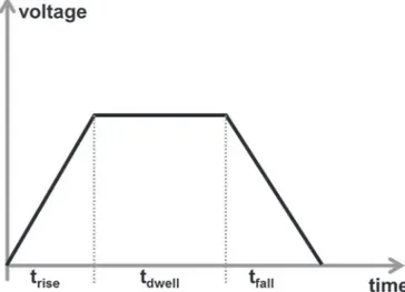
The experimental setup is sketched in Fig. 1in top and side views. The apparatus has been designed and constructed by CER-ADROP (Limoges, France) for this study. It consists of a printhead with a stainless steel plate of 256 nozzles equipped with a stro-boscopic image acquisition system. The latter consists in cameras, a light emitting diode (LED), controlled by a computer software. Three different cameras are connected to the setup, each with a different angle. However, only one can be used at a time for the stroboscopic sequence acquisition. A trapezoidal voltage waveform consisting of a rise trise, a peak hold at the maximum voltage V
during a dwell time tdwelland a fall to 0 V during a time tfallis
applied to the nozzle to pump and expel the liquid (see Fig. 2), working in the shear mode. The duration of each segment of the Fig. 1. Schematic of the experimental setup, side and top views. Drops are ejected downwards from a printhead. LED pulses and video camera acquisitions are triggered to acquire successive snapshots of the ejection process stroboscopically. Three cameras (L, R and C) are connected but only one is used at a time.
waveform can be selected independently, but the total time cannot exceed 15
μ
s due to printhead limitations. Jetting is a continuousprocess, where the ejection frequency, i.e. the time between two subsequent drops, can be selected and usually lies in the kHz range.
2.4. Image acquisition
Filament ejection, thinning and breakup are recorded as a collection of single frames. Image acquisition is triggered and synchronized with lighting to obtain a stroboscopic reconstruction of the jetting process, according to the timing diagram inFig. 3. However, each image belongs to a different jetting sequence. The smallest apparent time lapse between two frames Δt is one microsecond.
Some typical snapshots are shown inFig. 4. The shape of the thread is asymmetric about the minimum (Wang et al., 2012;
Eggers, 1997), which can be located either just below the droplet head, or near the nozzle. After background substraction, for each frame the length L and minimum radius Rminare obtained from a
Gaussian curve fit to each horizontal line of pixels.
3. Results and discussion
3.1. Inks
The physical parameters of interest for all inks have been carefully measured. They are summarized in Table 1, with the recommended ranges given by the printhead manufacturer. The densities are very similar for all the inks. The same can be said for surface tension values except for the non-particulate inks made from glycerol and PEG. The main difference lies in the shear viscosity values. All inks have a viscosity rate index n rather close to one, which is representative for shear-thinning particulate inks. A lower exponent would indicate strong interactions within the fluid, which is often not compatible with colloidal suspension stability. Moreover, the rheological behaviour has been measured only up toγ ̇ =1000 s−1, and it is not excluded that the properties
may change at higher shear rates, such as the ones exerted during fluid ejection from the printhead (Wang et al., 2010).
A general approach to the dynamics of filament growth and breakup in different configurations has been conducted in the literature, leading to several hypotheses for the thinning behaviour (McKinley, 2005;Cooper-White et al., 2002;Rothert et al., 2001). The physical parameters involved are viscosity, inertia and ca-pillarity. The relative importance of these three forces is re-presented by the Ohnesorge numberOh=η/ L0ρλ, with
η
beingthe shear viscosity,
ρ
the density,λ
the surface tension and L0acharacteristic length. Oh3 can also be viewed as the ratio of a
characteristic viscous timetvisc=η ρλ3/ 2over the Rayleigh inertial
time, defined astRay= ρL /03λ. The characteristic non-dimensional
parameter used in the literature is called the ejection ratio Z, and is defined asZ=Oh−1. Early studies claimed that only a limited range
of ejection ratios was available:1<Z<10(Reis and Derby, 2000). However, recently wider ranges have also been reported ( Moga-licherla et al., 2013), indicating that this criterion does not seem relevant. It should be noted that Z is calculated with the as-sumption of a simple fluid. The particulate nature of the ink, or viscoelastic effects that may arise at higher frequencies are not considered, and may account for this discrepancy between the reports in the literature. Moreover, ink viscosity and surface ten-sion have to fall within given ranges in order for the ink to be ejected on a given printhead. If viscosity is too high, the fluid cannot be ejected at all. On the other hand, the filament breaks in multiple points and satellite droplets are formed if viscosity is too low and surface tension is high. In the case of low surface tension, the ink will wet the printhead instead of forming a filament. The overall operating range of Z falls into an intermediate regime, where inertia plays an important role.
Several characteristic time and lengthscales could be calculated with the physical parameters reported inTable 1, as summarized inTable 2. The viscous length is defined as follows: Lvisc=η ρλ2/ .
The characteristic length in Oh and tRaywas taken as the nozzle
radius, i.e.L0=R0=21or 26
μ
m depending on the printhead usedfor the experiment. Wherever the viscosity is required, the value at 1 s"1, corresponding to the value of the consistency K is used.
For all inks, Lvisc≤R0, confirming that R0is indeed the relevant
lengthscale. All ejection ratios fall into the ejectability range
<Z<
1 10except for redMF and gly38, which could nevertheless be ejected successfully. This confirms that ejectability ranges in terms of Z are not relevant.
3.2. General behaviour
For each ink, several ejections were performed. All parameters of the driving waveform for the nozzle actuation were varied: pulse rise and fall durations, dwell time, and voltage amplitude. Fig. 2. Schematic of the actuation pulse for the nozzle. The voltage increases during
trise, then stays at a fixed value during tdwell, and then decreases to zero during tfall.
The duration of each segment of the waveform can be selected independently, but the total time cannot exceed 15 μs.
Fig. 3. Principle of stroboscopic sequence reconstruction. On top of the timing diagram, the consecutive actuation pulses are shown, with each drop emission. The bottom of the diagram shows the camera triggering sequence. The apparent time lapse between imagesΔtis illustrated.
Due to the stroboscopic measurement procedure, only stable ejections can be analysed. Thus, all the fluids were not ejected with the same set of actuation pulses. A snapshot just before fi-lament breakup is shown inFigs. 5and6for the different inks. The lowest voltage pulse was chosen for each ink.
Commercial inks (redMF and blackMF) and Ferrite 4 formula-tions formed straight filaments, whereas non-axisymmetric pro-files could be observed for all the other inks. A secondary thin thread as shown inFig. 4was visible near the nozzle in the case of blackMF, Ferrite 4 and SiO21, 2 and 3. During ferrite inks ejection,
a secondary bulge appeared at the nozzle exit. These observations will be discussed in more detail.
Despite similar properties as seen in Table 1, the overall
filament shape is different for every ink, indicating possible effects related to their particulate nature, or to the non-Newtonian character of the rheological behaviour. Let us estimate a shear rate in the nozzle by considering a steady state Poiseuille flow in a cylindrical duct of size R0. Based on a power law fluid, the
max-imum shear rate considering a Poiseuille flow in a cylindrical duct is: γ ̇ = = + ( ) ⎛ ⎝ ⎜ ⎞ ⎠ ⎟ AR K v R n n 2 3 1 1 max n 0 1/ 0 0
Since the typical velocity is of the order of 10 m/s as will be shown later, the shear rate varies from 106s"1in the nozzle to 0 in the
filament. Even though the rate index is close to one, viscosity can vary by a factor two during the jetting process due to the large shear rate variation. The typical range of shear rate of 106s"1can
in turn be used to estimate a Péclet number in the particulate inks Fig. 4. Typical snapshots of a filament, near breakup. The dotted line indicates the position of the nozzle. Left: Ferrite 4, right: SiO24 (seeTable 1). The total length L and the minimum radius Rminare shown. On the right, the case with a secondary thread is highlighted.
Table 1
Physical parameters for the ejected fluids: particle radius a, solid content, density ρ, surface tension λ, consistency K and rate index (viscosity exponent) n. The particles sizes fall in the nanometric range, with rather low volume content. The deviation from a Newtonian viscosity (exponent 1) is 0.1 at the most. The printhead re-commended ranges are also given for reference.
Ink label a (nm) vol% (–) ρ(kg/m3) λ(mN/m) K (mPa sn) n (–)
redMF – – 1063 34.3 31.4 1 blackMF – – 917 36 16 1 gly38 – – 1100 68.3 3.38 1 gly60 – – 1127 27.4 14.4 0.97 PEG8 – – 1050 60.1 8 1 PEG11 – – 1070 59.7 16 1 SiO21 10 15 1259 30.2 31 0.94 SiO22 10 15 1200 32.2 17.5 0.97 SiO23 10 15 1210 33.1 24.1 0.94 SiO24 10 15 1205 31.7 25.1 0.98 Ferrite 4 80 & 170 4 1230 33.9 8.4 0.98 Ferrite 8 80 & 170 8 1390 33 25 0.90 Recommended ranges 24–36 10–20 1 Table 2
Characteristic time and lengthscales for the ejected fluids: viscous length Lvisc,
viscous time tvisc, Rayleigh time tRay, Ohnesorge number Oh and its inverse the
ejection ratio Z.
Ink label Lvisc(μm) tvisc(μs) tRay(μs) Oh (–) Z (–)
redMF 27 25 17 1.13 0.9 blackMF 8 3 15 0.61 1.6 gly38 0.152 0.008 12 0.09 11.8 gly60 7 4 20 0.56 1.8 PEG8 1 0.1 13 0.22 4.5 PEG11 4 1 13 0.44 2.3 SiO21 25 26 27 0.99 1 SiO22 8 4 26 0.55 1.8 SiO23 15 11 25 0.75 1.3 SiO24 17 13 19 0.89 1.1 Ferrite 4 2 0.422 25 0.26 3.9 Ferrite 8 14 10 27 0.72 1.4
= γ ̇ Pe
D/a
max
0 2
, where D0is the diffusion coefficient calculated with a
solvent viscosity of 10 mP s. They are summarized inTable 3. Both ferrite size populations have a high Pe. Silica has a rather lower Pe number, but still superior to one. These values indicate that the behaviour is dominated by flow and not by Brownian motion.
The minimum radius evolution as a function of time for the Ferrite 8 formulation is plotted in Fig. 7. For each of the curves obtained with different actuation pulses (50 V with a waveform 2– 11–2
μ
s, 69 V and 2–10–2, 2–6–2, 10–2–2, 2–2–10μ
s), the pulseduration tpulse=trise+tdwell+tfall has been subtracted such that
− =
t tpulse 0is the end of the pulse. As can be seen, except for data
dispersion arising from the uncertainty in the minimum detection, all the data collapse on a single master curve. We observe no effect of the driving waveform on the thinning process. This is the case for all the inks. For each fluid, the average minimum radius over all
the experiments was calculated and is subsequently called Rminfor
simplicity. It appears that the filament thinning behaviour is the same whatever the drop generation method.
The breakup time tbwas obtained from the last time tendwhere
the thread is connected to the printhead by calculating
+ Δ
tend 0.5 t. tbwas plotted against tRayin order to find a scaling
behaviour, as presented in Fig. 8. The data show a linear re-lationship, as can be seen from the slope of almost one on the log– log scale. Thus, the time to breakup is controlled mainly by inertial effects, as there is no viscosity in the Rayleigh time. Moreover, it appears that both Newtonian and non-Newtonian fluids obey the same law, indicating no effect of the viscosity power law exponent. The linear coefficient for the breakup time was obtained from a linear fit of the type y¼ax, and the slope was found to be 2.69 (see
Fig. 8). The linear stability analysis for a symmetric perturbation Fig. 5. Snapshots just before filament breakup for non-particulate inks (scale: 50 μm). The nozzle is at the top of the image. The fluids show straight profiles for both black and red MF, but non-axisymmetric ones for all the other inks. A secondary thread is observed for blackMF and PEG8.
growth in the systems givestbreakup≃2.74tRayleigh(see for example
Dumouchel, 2008), which is very close. However, for most of the inks a non-axisymmetric breakup is observed, which is in con-tradiction with Rayleigh's work which states that axisymmetric disturbances should grow faster than non-axisymmetric ones. Contrary to the findings ofvan Deen et al. (2013)andBonnoit et al. (2012), no acceleration due to the presence of particles can be observed. However, the colloids used in this study are three orders of magnitude smaller than those used in the cited literature (tens of nanometers in diameter versus a few micrometers). Thus, at the length scales considered here, the inks can still be described as a continuum medium, as far as viscosity but also surface tension are concerned. The liquid draining and particle reorganization may thus still occur, but only when the filament is much thinner than
Fig. 6. Snapshots just before filament breakup for particulate inks (scale: 50 μm). The nozzle is at the top of the image. As for the non-particulate inks inFig. 5, both straight (Ferrite 4) and non-axisymmetric profiles can be observed, as well as secondary threads located near the nozzle.
Table 3
Estimates of Péclet numbers for the particulate inks. All inks are flow-dominated.
Ink Pe
SiO2 46
Ferrite 2.103
22.103
Fig. 7. Minimum radius Rminas a function of time shifted by the pulse duration,
here for Ferrite 8. Each symbol represents a different nozzle actuation pulse: 50 V with a waveform 2–11–2 μs, 69 V and 2–10–2, 2–6–2, 10–2–2, 2–2–10 μs (þ, n, % , ○). All the experiments fall on the same master curve.
that can ever be observed with optical techniques, and also at timescales below the microsecond. The studies of the stability of liquid jets have been reviewed in detail in referenceDumouchel (2008), in relation with surrounding gas and fluid Weber numbers
Wef g, defined as =
ρ λ
We 2f g,v R20
. In our case, 0.05<Weair <1, and <We <
39 ink 886. According to the classification fromDumouchel (2008), the system belongs to the Rayleigh regime (straight fila-ment).Fig. 9shows the evolution of maximum thread length as a function of maximum velocity, for all the inks. The Rayleigh regime can be inferred from the monotonic behaviour: the breakup length increases with the velocity. However, we observe almost always a non-axisymmetric filament.
The loss of axisymmetry has been attributed to different factors for the case of complex fluids, such as particle migration towards the edge of the contact line occurring when the ink dries around the nozzle (coffee stain effect), resulting in non-symmetric wetting properties (Wang et al., 2012). Imperfections in the nozzle, caused
for example by partial clogging, may also induce specific jet shapes. This often leads to poor jetting quality. However, in our case the jetting proved to be perfectly stable, since the strobo-scopic sequence shows no discrepancy in the shape of the filament between two adjacent frames. Since every frame belongs to a different jetting sequence, this finding indicates that the non-isymmetric shape is perfectly reproducible. The loss of ax-isymmetry occurs for the lower part of the filament, whereas the part attached to the nozzle is perfectly straight. This deformation may thus be attributed to viscoelastic effects. Some authors in-vestigated the non-axisymmetric breakup of liquid columns or columns of compound fluids (Ruo et al., 1992;Chen et al., 2008). Yang et al. focus on viscoelastic fluids (Yang et al., 2013), and show that the instability grows faster for this type of rheological beha-viour. Thus, it appears that the viscoelastic properties of the inks are more important than expected at first. This behaviour has been reported for particulate inks (Wang et al., 2012;Connington et al., 2015), and has also been investigated in relation with the sur-rounding air flow for ejection of viscoelastic fluids (Yang et al., 2013). In the situation investigated in the literature, the non-ax-isymmetric disturbance growth led to an overall filament breakup in a non-symmetric way (Dumouchel, 2008;Zhao et al., 2014). For fluid with micron size particles such as coal-water slurry (Zhao et al., 2014), a clear link was established between viscoelastic properties and the breakup length during primary atomization of the jet. In our case, there is a single bulge in the filament profile. This may be due to the propagation of an acoustic wave originated from the pulse, or the elastic response to fluid elongation. For the sake of comparison, Fig. 10 shows the profile obtained for a strongly viscoelastic ink formulated with poly-vinyl alcohol (PVA) at 25 wt% in water. In the case of PVA, the ink is clearly viscoelastic due to high PVA content, and the deformation is very pronounced. For the other inks studied, there can be a small viscoelastic con-tribution originating from the different additives (surfactants, humectants) required for ink formulation.Fig. 11shows the profile taken at the same (apparent) time in the jetting sequence, with three different cameras. Each camera looks at the printhead with a different angle, and it is clear that the central picture of the montage does not exhibit the bulge. This camera is perfectly per-pendicular to the printhead (see top view in Fig. 1, camera C). Thus, after considering all the observation angles for the fluids, it appears that the non-axisymmetric filament profile is observed for all the inks except Ferrite 4. The viscoelastic behaviour can be highlighted by studying the thinning of the filament.
3.3. Filament thinning
The thinning behaviour of the minimum thread radius Rmin
with time has been reported to depend on the relative magnitude of the different contributions. The time-to-breakupτ =tb−tis the
relevant time axis. For viscosity dominated regimes, R ∝τα min . If
viscosity obeys a power law type behaviour of the formη=Kγn 1̇−,
the minimum radius decays as Rmin∝τn. As the filament width
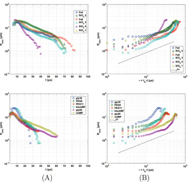
decreases, inertia and capillarity become more important, and the system can enter a different regime. Eventually, close to breakup all contributions become equal and a final regime is reached where Rmin∝τ2/3(McKinley, 2005;McKinley and Tripathi, 2000; Cooper-White et al., 2002).
The filament thinning passes through several regimes, high-lighted on the graphs inFig. 12. Let us first consider the particulate fluids. In the first column (A), Rminis plotted as a function of time t
on a lin–log scale. A very clear exponential decay region can be seen for all the fluids, followed by another regime. The first re-gime, whereR ∝e− λ
min t/cis predicted when the elastic contribution
is large (Cooper-White et al., 2002;McKinley, 2005), withλc=η/G
the characteristic relaxation time of the fluid, with G being the Fig. 8. Breakup time tbas a function of the Rayleigh time tRayfor the different inks.
A power law fit with an exponent close to 1 can be obtained as shown on the loglog inset, further demonstrated on the linear plot, where a slope of 2.69 can be fitted to the data. The symbol colour represents the viscosity rate index of the ink. (For interpretation of the references to colour in this figure caption, the reader is re-ferred to the web version of this paper.)
Fig. 9. Maximum thread length as a function of vendfor all the fluids. Each symbol
corresponds to a different fluid, the symbol size corresponds to tRay. There is a
monotonic increase of the length with velocity, indicating that all inks break up in the Rayleigh regime according toDumouchel (2008). (For interpretation of the references to colour in this figure caption, the reader is referred to the web version of this paper.)
elastic modulus.
The second regime is highlighted on the second graph (B), where Rminis plotted as a function of the time-to breakup
τ
. Onthis graph, the power decay region, where Rminvaries as τ2/3, can
also clearly be seen. This regime starts when the exponential de-cay ends, and was predicted for inviscid fluids (Yildirim and Ba-saran, 2006; Cooper-White et al., 2002). SiO24 seems to be
de-caying as
τ
1, which is in turn predicted for regions where viscositydominates, or conversely very close to breakup when all the contributions become important. This tail can be seen for the other
inks except for SiO22, which has the lowest viscous time. This last
regime can thus happen at even shorter timescales than what can be observed in this setup. Thus, we found that despite the small amount of additives in the ink formulation, the viscoelastic properties become visible at the time and lengthscales involved in inkjet printing. This is also the case for the non-particulate inks, as can be seen from the second line inFig. 12. Despite PEG being a polymer, viscoelastic effects were not supposed to be strong since the concentration is low. The elastic moduli obtained from the fit
∝ − λ
Rmin et/care summarized inTable 4. Ferrite 8 has a large value
Fig. 10. Montage of consecutive stroboscopic snapshots of the ejection process of a viscoelastic ink (PVA, 25 wt% in water), shown for the sake of comparison. The actuation pulse rise, dwell and fall times are 5 μs, and the voltage is 120 V. The distorted profile is perfectly reproducible as there is no discrepancy between the frames, which belong in reality to different jetting sequences. Scalebar: 50 μm.
Fig. 11. Montage of snapshots taken at the same step of the sequence with three different cameras at different orientations. When the deformation is perfectly perpendicular to the camera, it cannot be seen clearly (central image). Scalebars: 100 μm.
Fig. 12. Minimum radius plotted against (A) the time t, and (B) the time-to breakup τ. On the first graph, an exponential decay region is observed, followed by a rapid thinning. This second regime is more clearly seen on the second graph, with a decayRmin∝τ2/3or τ1. The first line is for particulate fluids, and the second for solutions.
of elastic modulus, which confirms the origin of the axisymmetry loss observed inFig. 6. On the other hand, Ferrite 4 has the lowest elastic modulus, and displays axisymmetric profiles.
Solutions and particulate fluids of similar ejection ratio Z were then compared in order to detect non-Newtonian effects.Fig. 13
shows the thinning behaviour as a function of the time to breakup
τ =tbreak−t for three fluids: SiO2 – 1, SiO2 – 4, and redMF with ≃
Z 1. The minimum radius was divided by Lvisc to obtain a
di-mensionless parameter. The log-log scale helps us to identify the scaling behaviour. The data points close to zero are obtained when the filament is at its thinnest, resulting in a worse signal-to-noise ratio, and may not be completely reliable. Thus, the apparent slowing of the break-up process cannot be fully trusted. This dif-ficulty arises from the fact that the filament width becomes less than one pixel. OnlySiO2 – 1andSiO2 – 4exhibit a
τ
1decay; allfluids decay with aτ2/3. Despite Z being very close, the behaviour is
clearly different. However, this is the case even for two similar SiO2inks, showing that a slight formulation change can result in a
completely different ejection scenario.
3.4. Actuation pulse
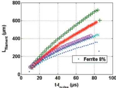
The pulse waveform parameters have been reported to have complex effects on the ejected drop characteristics (Reis and Derby, 2000;Jang et al., 2009).Fig. 14shows the variation of the filament length with time for Ferrite 8. Since the pulse does have some influence on drop velocity, there is a strong disparity in the thread lengths. The effect of the driving pulse on the filament growth has been studied by calculating the instantaneous growth
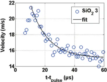
ratev t( ) =dLdtfilfor all fluids and pulses. v(t) was obtained from the slope of piecewise affine fitting to the filament length data. This procedure allowed us to smooth out the results. A typical result is shown inFig. 15, for two different pulses with Ferrite 4. From the data, it can be seen that the growth rate decreases with time, starting at a value v0and decreasing to reach a plateau vend. In
some cases, an increase of the velocity can be observed at first, before this exponential decay. It is the case for SiO23, as shown in Fig. 16. A curve of the formAe−λt+v
endwas fitted to all growth rate
data in the decreasing region, with a very good agreement as can be seen inFigs. 15and16.
With the viscosity exponents reported inTable 1, the viscosity variation over the shear rates involved ranges from around 75 to 25% of the consistency values. Since thinning and breakup do not involve high shear rates, all characteristic times were calculated using the low shear viscosity (consistency in Table 1). However, the viscosity range criterion for ink ejectability should use a higher shear rate viscosity value because ejectability is controlled by the flow in the nozzle.
Fig. 17shows the growth rate variation for Silica 2 as a function of voltage, for different pulses. The growth rate seems proportional to the peak voltage, with a shift of the curves for different pulse Table 4
Elastic moduli obtained from a fitR ∝e− λ
min t c/ , withλc=η/G.
Ink PEG8 PEG11
G (MPa) 1.67 4.02
Ink SiO2– 2 SiO2– 3 Ferrite 4 Ferrite 8
G (MPa) 1.82 4.84 0.84 4.49
Fig. 13. Evolution of the dimensionless minimum radiusRmin/Lviscas a function of
the time to breakup τ, for fluids with Z close to 1. The lines correspond to different theoretical power laws: 1 for viscosity-dominated regime, 2/3 for inertial regime. (For interpretation of the references to colour in this figure caption, the reader is referred to the web version of this paper.)
Fig. 14. Filament length Lfilas a function of time shifted by the pulse duration, for Ferrite 8. Each symbol represents a different nozzle actuation pulse:!: 2–11–2 μs 50 V, þ : 2–10–2 μs 69 V, n: 2–6–2 μs 69 V, % : 10–2–2 μs 69 V, ○: 2–2–2–10 μs 69 V. For this parameter, the actuation waveform has a strong influence.
Fig. 15. Filament growth rate v as a function of time shifted by the pulse duration, for Ferrite 2. Two different pulses are shown. The growth rate curves can be fitted usingAe−λt+vend.
durations, as expected from literature (Jang et al., 2009).
The same pulse did not necessarily lead to successful ejection for all the fluids. When several driving pulses were available for a given fluid, an affine fit v=β(V−Vmin) was performed for the
growth rate data as a function of driving voltage. Every pulse dwell time was considered separately. This allows us to determine the minimum driving voltage for each fluid, on a given nozzle. The results are plotted inFig. 18. It appears that a single value of Vmin
can be determined for each fluid. Except for the PEG 8 solution, the behaviour seems to be linear with tRay.
4. Conclusion
In this study, several inks consisting of both solutions and particulate suspensions were ejected on an inkjet printing device, and the filament growth and breakup were analysed in detail. Original results for ceramic inks originally formulated for actual 3D shaping were obtained. Due to the micronic time and lengthscales involved, a stroboscopic approach, with a specific image analysis technique, had to be set up. All inks were for-mulated with their high shear viscosity and their surface tension values within the acceptable range specified by the printhead supplier.
The general behaviour was different for all the tested inks: some presented a secondary microthread, others non-axisym-metric profiles, or a secondary bulge near the nozzle. The first finding was the confirmation that the nozzle actuation pulse had no effect on the thinning behaviour itself. The effect of the pulse could be seen on the filament growth rate.
Due to the time and lengthscales involved, not all the breakup stages could be observed. The fluids were mainly controlled by inertia, thus the breakup time scaled as the Rayleigh time. As far as the current analysis is concerned, it seems that the non-New-tonian nature of the fluid played no particular role on the scaling of the breakup time. However, the viscoelastic behaviour seems to have a larger impact than expected from the ink formulation alone, where viscoelastic additives are non-existent or in very low amount. In the current study only moderately non-Newtonian fluids could be ejected due to the restrictions on the printhead. It would be interesting to test more complex fluids. In this case, a live observation setup might be necessary, in order to observe unsteady ejection.
Acknowledgements
The authors are grateful for financial support by the French DGA, the Limousin Region Council (FEDER) in the framework of the CermJet program (7th call for FUI Research Program).
References
Ainsley, C., Reis, N., Derby, B., 2002. Freeform fabrication by controlled droplet deposition of powder filled melts. J. Mater. Sci. 37 (15), 3155–3161. Basaran, O.A., Gao, H., Bhat, P.P., 2013. Nonstandard inkjets, In: Annual Review of
Fluid Mechanics, vol. 45, pp. 85–113.
Beaudrouet, E., Vivet, A., Lejeune, M., Santerne, C., Rossignol, F., Dossou-Yovo, C., Mougenot, M., Noguera, R., 2014. Stability of aqueous barium titanate suspen-sions for mlcc inkjet printing. J. Am. Ceram. Soc. 97 (4), 1248–1255.
Bhatti, A.R., Mott, M., Evans, J.R.G., Edirisinghe, M.J., 2001. Pzt pillars for 1–3 composites prepared by ink-jet printing. J. Mater. Sci. Lett. 20 (13), 1245–1248.
Blazdell, P.F., Evans, J.R.G., Edirisinghe, M.J., Shaw, P., Binstead, M.J., 1995. The computer aided manufacture of ceramics using multilayer jet printing. J. Mater. Sci. Lett. 14 (22), 1562–1565.
Bonnoit, C., Bertrand, T., Clment, E., Lindner, A., 2012. Accelerated drop detachment in granular suspensions. Phys. Fluids 24 (4).
Chen, F., Ruo, A.C., Chang, M.H., 2008. On the nonaxisymmetric instability of round Fig. 16. Filament growth rate v as a function of time shifted by the pulse duration,
for SiO23. At the beginning, the velocity increases, then decreases exponentially.
Fig. 17. Filament growth rate v0as a function of peak voltage V, for the Silica 2 ink. Each symbol corresponds to a different dwell time, also indicated on the colorbar. Ae seems to lead to a larger end velocity. An affine relationvend=β(V−Vmin)can be
fitted to the data. (For interpretation of the references to colour in this figure caption, the reader is referred to the web version of this paper.)
Fig. 18. Minimum driving pulse voltage as a function of Rayleigh time, grayscale:
Oh number. Vminis obtained from an affine fit for velocity as a function of voltage
pulse (seeFig. 17). Non-particulate fluids are represented as circles, silica inks as stars and ferrite as squares. (For interpretation of the references to colour in this figure caption, the reader is referred to the web version of this paper.)
liquid jets. Phys. Fluids 20 (6).
Christanti, Y., Walker, L.M., 2001. Surface tension driven jet break up of strain-hardening polymer solutions. J. Non-Newton. Fluid Mech. 100 (1–3), 9–26.
Connington, K.W., Miskin, M.Z., Lee, T., Jaeger, H.M., Morris, J.F., 2015. Lattice Boltzmann simulations of particle-laden liquid bridges: effects of volume fraction and wettability. Int. J. Multiph. Flow 76, 32–46.
Cooper-White, J.J., Fagan, J.E., Tirtaatmadja, V., Lester, D.R., Boger, D.V., 2002. Drop formation dynamics of constant low-viscosity, elastic fluids. J. Non-Newton. Fluid Mech. 106 (1), 29–59.
Dossou-Yovo, C., Mougenot, M., Beaudrouet, E., Bessaudou, M., Bernardin, N., Charifi, F., Coquet, C., Borella, M., Noguera, R., Modes, C., Lejeune, M., Laurier, P., Detemmerman, D., Escure, P., Laville, H., Delhotes, N., Verdeymes, S., 2012. In-kjet printing technology: a novel bottom-up approach for multilayer ceramic components and high definition printed electronic devices. In: 8th Interna-tional Conference and Exhibition on Ceramic Interconnect and Ceramic Mi-crosystems Technologies, CICMT, pp. 55–66.
Dumouchel, C., 2008. On the experimental investigation on primary atomization of liquid streams. Exp. Fluids 45 (3), 371–422.
Eggers, J., 1997. Nonlinear dynamics and breakup of free-surface flows. Rev. Mod. Phys. 69 (3), 865–929.
German, G., Bertola, V., 2010. Formation of viscoplastic drops by capillary breakup. Phys. Fluids 22 (3), 1–11.
Gratton, M., Witelski, T., 2008. Coarsening of unstable thin films subject to gravity. Phys. Rev. E 77.
Jang, D., Kim, D., Moon, J., 2009. Influence of fluid physical properties on ink-jet printability. Langmuir 25 (5), 2629–2635.
Larson, R.G., 1998. The Structure and Rheology of Complex Fluids 1. University Press, New York.
Lee, A., Sudau, K., Ahn, K.H., Lee, S.J., Willenbacher, N., 2012. Optimization of ex-perimental parameters to suppress nozzle clogging in inkjet printing. Ind. Eng. Chem. Res. 51 (40), 13195–13204.
Liou, T.M., Chan, C.Y., Shih, K.C., 2009. Effects of actuating waveform, ink property, and nozzle size on piezoelectrically driven inkjet droplets. Microfluid. Nano-fluid., 1–12.
Mathues, W., McIlroy, C., Harlen, O.G., Clasen, C., 2015. Capillary breakup of sus-pensions near pinch-off. Phys. Fluids 27 (9).
McKinley, G.H., Tripathi, A., 2000. How to extract the Newtonian viscosity from capillary breakup measurements in a filament rheometer. J. Rheol. 44 (3), 653–670.
McKinley, G. H., 2005. Visco-elasto-capillary thinning and break-up of complex fluids. Rheology reviews, The British Society of Rheology, 1-49.
Meinhart, C.D., Zhang, H., 2000. Flow structure inside a microfabricated inkjet printhead. J. Microelectromech. Syst. 9 (1), 67–75.
Mogalicherla, A.K., Lee, S., Pfeifer, P., Dittmeyer, R., 2013. Drop-on-demand inkjet printing of alumina nanoparticles in rectangular microchannels. Microfluidics Nanofluidics, 1–12.
Mohebi, M.M., Evans, J.R.G., 2002. A drop-on-demand ink-jet printer for combina-torial libraries and functionally graded ceramics. J. Comb. Chem. 4 (4), 267–274.
Morris, G., Hadler, K., Cilliers, J., 2015. Particles in thin liquid films and at interfaces. Curr. Opin. Colloid Interface Sci. 20 (2), 98–104.
Noguera, R., Lejeune, M., Chartier, T., 2005. 3d fine scale ceramic components formed by ink-jet prototyping process. J. Eur. Ceram. Soc. 25 (12), 2055–2059. Pierron, P., Allaman, S., Soucemarianadin, A., 2001. Dynamics of jetted liquid
fila-ments. In: International Conference on Digital Printing Technologies, IS and T's NIP17: International Conference on Digital Printing Technologies, pp. 308–312. Reis, N., Derby, B., 2000. Ink jet deposition of ceramic suspensions: modelling and experiments of droplet formation. In: Solid Freeform and Additive Fabrication, vol. 625, pp. 117–122.
Reis, N., Seerden, K.A.M., Derby, B., Halloren, J.W., Evans, J.R.G., 1999. Direct inkjet deposition of ceramic green bodies: II—jet behaviour and deposit formation. Mater. Res. Soc. Symp.—Proc. 542, 147–152.
Rothert, A., Richter, R., Rehberg, I., 2001. Transition from symmetric to asymmetric scaling function before drop pinch-off. Phys. Rev. Lett. 87 (8), 845011–845014. Ruo, A.C., Chen, F., Chang, M.H., 1992. Linear instability of compound jets with
nonaxisymmetric disturbances. Phys. Fluids 21 (1).
Seerden, K.A.M., Reis, N., Derby, B., Grant, P.S., Halloran, J.W., Evans, J.R.G., 1999. Direct ink-jet deposition of ceramic green bodies: I—formulation of build materials. Mater. Res. Soc. Symp.—Proc. 542, 141–146.
Seerden, K.A.M., Reis, N., Evans, J.R.G., Grant, P.S., Halloran, J.W., Derby, B., 2001. Ink-jet printing of wax-based alumina suspensions. J. Am. Ceram. Soc. 84 (11), 2514–2520.
Singlard, M., Aimable, A., Lejeune, M., Dossou-Yovo, C., Poncelet, M., Noguéra, R., Modes, C., 2014. Aqueous suspensions of glass silicate dielectric powders for ink-jet printing applications. Powder Technol. 266, 303–311.
van Deen, M.S., Bertrand, T., Vu, N., Quéré, D., Clément, E., Lindner, A., 2013. Par-ticles accelerate the detachment of viscous liquids. Rheol. Acta 52 (5), 403–412. Wang, X., Carr, W.W., Bucknall, D.G., Morris, J.F., 2010. High-shear-rate capillary
viscometer for inkjet inks. Rev. Sci. Instrum. 81 (6).
Wang, X., Carr, W.W., Bucknall, D.G., Morris, J.F., 2012. Drop-on-demand drop for-mation of colloidal suspensions. Int. J. Multiph. Flow 38 (1), 17–26.
Wijshoff, H., 2010. The dynamics of the piezo inkjet printhead operation. Phys. Rep. 491 (4–5) 77–177.
Xiang, Q.F., Evans, J.R.G., Edirisinghe, M.J., Blazdell, P.F., 1997. Solid freeforming of ceramics using a drop-on-demand jet printer. Proc. Inst. Mech. Eng. Part B: J. Eng. Manuf. 211 (3) 211–214.
Yang, L.J., Tong, M.X., Fu, Q.F., 2013. Linear stability analysis of a three-dimensional viscoelastic liquid jet surrounded by a swirling air stream. J. Non-Newton. Fluid Mech. 191, 1–13.
Yildirim, O.E., Basaran, O.A., 2006. Dynamics of formation and dripping of drops of deformation-rate-thinning and -thickening liquids from capillary tubes. J. Non-Newton. Fluid Mech. 136 (1), 17–37.
Zhao, X., Evans, J.R.G., Edirisinghe, M.J., Song, J.H., 2002. Ink-jet printing of ceramic pillar arrays. J. Mater. Sci. 37 (10), 1987–1992.
Zhao, H., Hou, Y.B., Liu, H.F., Tian, X.S., Xu, J.L., Li, W.F., Liu, Y., Wu, F.Y., Zhang, J., Lin, K.F., 2014. Influence of rheological properties on air-blast atomization of coal water slurry. J. Non-Newton. Fluid Mech. 211, 1–15.