OATAO is an open access repository that collects the work of Toulouse
researchers and makes it freely available over the web where possible
Any correspondence concerning this service should be sent
to the repository administrator:
tech-oatao@listes-diff.inp-toulouse.fr
This is an author’s version published in:
http://oatao.univ-toulouse.fr/26131
To cite this version:
Coquery, Clément
and Carosio, Federico and Negrell, Claire and Caussé,
Nicolas
and Pébère, Nadine
and David, Ghislain New bio-based
phosphorylated chitosan/alginate protective coatings on aluminum alloy obtained by
the LbL technique. (2019) Surfaces and Interfaces, 16. 59-66. ISSN 2468-0230
New bio-based phosphorylated chitosan/alginate protective coatings on
aluminum alloy obtained by the LbL technique
Clément Coquery
a,b, Federico Carosio
c, Claire Negrell
a, Nicolas Caussé
b, Nadine Pébère
b,
Ghislain David
a,⁎aInstitut Charles Gerhardt (ICG), UMR-5253, CNRS, UM, ENSCM, Ingénierie et Architectures Macromoléculaires (IAM), 240 Avenue Emile Jeanbrau, 34296, Montpellier
Cedex 5, France
bCIRIMAT, Université de Toulouse, CNRS, INPT, ENSIACET, 4 allée Emile Monso, CS 44362, 31030, Toulouse Cedex 4, France cDipartimento di Scienza Applicata e Technologia, Politecnico di Torino, sede di Alessandria, Viale Teresa Michel 5, 15121 Alessandria, Italy
A R T I C L E I N F O Keywords: Phosphorylated chitosan Layer-by-layer assembly Coating Aluminum alloy
Electrochemical impedance spectroscopy
A B S T R A C T
Bio-based coatings were obtained by the layer-by-layer (LbL) technique from a native chitosan (Mw ≈ 30,000 g mol−1) or from two synthesized phosphorylated chitosan of different molecular weights
(Mw≈ 30,000 g mol−1and Mw≈ 250,000 g mol−1) combined with alginate and used for corrosion protection
of an aluminum alloy (AA) 3003. First, the LbL growth was monitored by Fourier transform infrared spectro-scopy on silicon wafers. Cross-sections of Si wafers were examined by scanning electron microspectro-scopy allowing the films thickness to be measured. With the native chitosan and in the presence of 10 bilayers, the LbL thickness was about 200 nm, whereas it was about 300 nm with the phosphorylated chitosan of low molecular weight and about 500 nm with the phosphorylated chitosan of high molecular weight. Then, the bio-based coatings were deposited on the AA3003 by the LbL technique and their protective properties were evaluated by electro-chemical impedance spectroscopy (EIS) during immersion in a 0.1 M Na2SO4solution. It was shown that the
three LbL coatings improved the corrosion resistance of the AA3003. The resistance values, extracted at low frequency on the impedance diagrams were attributed to the resistance of the aluminum oxide layer (Rox). The
Roxvalues were at least two orders of magnitude higher for the coated samples (108Ω cm2) compared to the
uncoated one (5 105Ω cm2). There was no significant difference between the different LbL coatings, which
mainly acted by decreasing the active surface area and have a limited barrier effect.
1. Introduction
The Layer-by-Layer (LbL) deposition represents an innovative and interesting alternative for the development of coatings for several ap-plications such as flame retardants[1,2], electrochromic[3] applica-tions, medical and bioapplications [4,5] but also nano-engineering
[6,7]. The LbL technique is attractive mainly due to an easy integration of functional materials, treatment under ambient conditions (room temperature and atmospheric pressure) and ecological characteristics (solvent is mainly water and concentrations of solutions/dispersions are less than 1 wt.%). LbL coatings are elaborated on a substrate by the sequential adsorption of chemical species based on one or more func-tional interactions. The most common interaction is provided by the electrostatic attraction[8,9]; indeed, the alternative adsorption of op-posites charged polyelectrolytes allows the accumulation of structured laminated or strongly interpenetrated coatings [10]. Among available
polyelectrolytes, polysaccharides can be rather good candidates to perform fully bio-based LbL systems, due to their low toxicity, biode-gradability and natural availability[11]. Chitosan is the second most abundant bio-based polysaccharide on the earth, after cellulose, and is the major component in crustaceans, exoskeletons, fungi or insects
[12]. Chitosan is a linear copolymer of glucosamine and N-acetyl-glu-cosamine, obtained from chitin by alkaline deacetylation[13]or from enzymatic pathway[14]. It is biocompatible[15], non-toxic[16], an-tibacterial[17]and can be used to form films[18,19]. Alginate is a linear polysaccharide formed from two monomers in different propor-tions bound in β-(1-4): mannuronate and guluronate[20]. Alginate-chitosan system has already been used for various applications such as, membrane manufacturing [21], biomedical [22] and drug delivery
[23]. Lawrie et al. studied the interactions between alginate and chit-osan using FTIR and XPS analyses[24]. The interest to prepare LbL coatings for corrosion protection purpose is to build a physical barrier
https://doi.org/10.1016/j.surfin.2019.04.010
⁎Corresponding author.
The procedure for obtaining the LbL films was independent of the substrates (Si wafer and AA3003). The negatively charged solution was prepared with sodium alginate (1 wt.%, pH = 5), while the positively
charged solution was prepared from either Nchitosan30, Pchitosan30 or Pchitosan250 (1 wt.%). Increasing the concentration of chitosan in so-lution should reduce the time per deposition step but, in the present work, concentration higher than 1 wt.% increased the viscosity of the solution, particularly for the Nchitosan[32]. The different chitosans were dissolved in deionized water and the pH was adjusted to 5 by addition of either acetic acid for the Nchitosan or NaOH for the Pchi-tosan. Both substrates (Si wafer and AA3003) were first dipped in a 0.1 wt.% BPEI (Branched PolyEthyleneImine) solution, leading to ca-tionic charges onto their surfaces[33]. The layers were then deposited by alternating immersion of the sample during 1 min in the solution containing the anionic polymer (alginate) and then, during 1 min in the solution containing the cationic polymer. After each immersion step, the sample was washed with deionized water and dried with warm air. Up to 10 layers (BL) were deposited. Only Nchitosan30 was used to develop the LbL coating because the Nchitosan250 was too viscous (even at low concentration) to enable LbL assembly. Thus, only three LbL systems were investigated: alginate/Nchitosan30, alginate/Pchi-tosan30 and alginate/Pchitosan250.
2.3. Analytical characterizations
Zeta potentials (ZP) were measured for 2 g L− 1of Nchitosan30 and
Pchitosan30 using a Zetasizer 2000 system (Malvern Instruments LtD.). The pH of the Nchitosan solution was adjusted at pH = 2 by adding acetic acid solution (1 M). The increase of pH was controlled by addi-tion of NaOH (1 M). The applied voltage for driving electrodes of the capillary electrophoresis cell was 10 V. The Zetasizer 2000 cell was rinsed with deionized water before each experiment. All experiments were conducted at 25 °C.
Coating growth was monitored using a Frontier Perkin-Elmer FTIR spectrophotometer (16 scans and 4 cm−1resolution) equipped with a
Ge/Ge crystal (depth of penetration 0.65 µm).
Cross-sections of the deposited coatings on Si wafers were imaged using a field-emission scanning electron microscope (FE-SEM, Zeiss Merlin 4248). Prior to FE-SEM observations Si cross-sections were chromium coated. A FEI Quanta 450 scanning electron microscope (SEM) was used for the surface characterization of the AA3003. Semi-quantitative analysis was performed by energy dispersive X-ray spec-troscopy (EDX) with a Ge detector (EDS Bruker Quantax SDD). EDX analyses were performed over different locations on the AA3003 sur-face before and after exposure to the Na2SO4solution.
2.4. Electrochemical characterizations
Electrochemical impedance measurements were performed in a classical three-electrode cell in which the coated LbL sample served as working electrode. A cylindrical glass tube was clamped onto the coated AA3003 plate, exposing a surface area of 14.9 cm2and filled
with 60 mL of a 0.1 M Na2SO4solution. A platinum electrode with a
large surface area and a mercury sulfate electrode (MSE) in a saturated potassium sulfate solution with EMSE= 0.64 V/SHE were used as
counter and reference electrodes, respectively. They were placed on the top of the glass tube by means of an electrode holder. The impedance diagrams were obtained for various immersion times (from 1 h to 48 h) to the Na2SO4 solution. It is generally accepted that SO42−are less
aggressive than Cl−. In the present study, a less aggressive electrolyte
was chosen to minimize the corrosion of the AA3003 substrate, thus allowing the LbL films to be compared according to their composition and thickness.
Electrochemical impedance measurements were carried out using a Biologic VSP apparatus. The diagrams were obtained under potentio-static conditions, at the open circuit potential, over a frequency range of 65 kHz to 10 mHz with 8 points per decade, using a 30 mV peak-to-peak sinusoidal voltage perturbation. The experiments were performed at room temperature (22 ± 3 °C). The linearity of the system was checked with strong interactions between each layer, thus preventing the
pe-netration of aggressive species through the coating towards the metal substrate. To our knowledge, only Gao et al. reported the use of chit-osan and alginate as component for a LbL coating for the protection of a magnesium implant in a biological fluid [22]. In their study, the coating was elaborated by spin-coating including forty cycles, each containing four layers: the first layer was the anionic alginate (ALG), the second one was the cationic mechano-growth factor MGF (i.e., a cationic polypeptide polymer), the third one was again the anionic ALG and the fourth one was the cationic chitosan. The resulting multi-layer coating was 18 μm thick. The authors found that the corrosion rate of the coated Mg alloy was slightly decreased by comparison with the uncoated sample, despite the substantial LbL coating thickness.
Phosphonic acid-containing polymers have numerous potential ap-plications as they exhibit attractive properties in term of adhesion [25]
and are of interest in corrosion inhibition [26,27]. Furthermore, the phosphorous-containing molecules or polymers can act as adhesion promoters for different s ubstrates s uch a s a luminum, z inc a nd steel
[28,29]. In our previous work, it was shown that the use of chitosan bearing phosphonic acid groups decreased the corrosion rate of a carbon steel by comparison with native chitosan [30]. Some LbL sys-tems, based on phosphorylated chitosan have already been published, aiming at providing new protective coatings for fireproof applications
[31]. To our knowledge, no alginate-phosphorylated chitosan system was so far developed through the LbL technique in order to develop protective coatings.
In the present work, elaboration and characterization of LbL coat-ings from alginate and native or phosphorylated chitosan of two dif-ferent molecular weights (30,000 g mol−1 and 250,000 g mol−1) were
first investigated on Si wafers, commonly used as model surfaces for the LbL characterization, in particular to follow the LbL growth. In this study, the LbL growth was monitored by Fourier transform infrared (FTIR) spectroscopy and the films thickness was determined by scan-ning electron microscopy (SEM). Then, the LbL coatings were deposited on aluminum (AA3003) plates and characterized by electrochemical impedance spectroscopy (EIS). The impedance of the coated samples was measured as a function of the exposure time to a 0.1 M Na2SO4
solution.
2. Experimental
2.1. Materials
Native chitosan, high molecular weight (Mw ≈ 250,000 g mol−1,
degree of deacetylation: 92%, henceforth called Nchitosan250) and medium molecular weight (Mw ≈ 30,000 g mol−1, degree of
deacety-lation: 92%, henceforth called Nchitosan30) were purchased from Glentham Life Sciences society. Phosphorylated chitosan from Nchitosan30 (henceforth called Pchitosan30) and from Nchitosan250 (henceforth called Pchitosan250) were synthesized according to our previous study [30]. Sodium alginate (from brown algae, Mw = 140,000 g mol−1) was purchased from Aldrich. Acetic acid
(>99.7%, Aldrich) was used as received. Deionized water was obtained from a Millipore Milli-Q purification s ystem. T he L bL c oatings were deposited onto an aluminum alloy 3003 (AA3003). Its chemical com-position in weight percent was: Cu = 0.05; Fe = 0.7; Mn = 1.5; Si = 0.6; Zn = 0.1 and Al to balance. The specimens consisted of 127 mm × 76 mm × 0.8 mm plates, purchased from Labomat. Before the deposition of the LbL coatings, the AA3003 samples were succes-sively cleaned with acetone and ethanol and dried for 10 min at 80 °C.
2.2. LbL assembly
by varying the signal amplitude. 30 mV was a good compromise to obtain the impedance diagrams without any dispersion.
3. Results and discussion
3.1. Determination of phosphorylated chitosan global charge vs pH
In our previous study[30], native chitosan, high molecular weight (Mw≈ 250,000 g mol−1, called Nchitosan250) and medium molecular
weight (Mw≈ 30,000 g mol−1, called Nchitosan30) were modified by
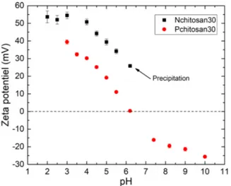
grafting phosphonic acid functions onto primary amines. About 20% of the primary amines were modified for each chitosan. In the present study, high and medium Mw phosphorylated chitosan (Pchitosan250 and Pchitosan30, respectively) were used to build the LbL coatings. According to the pH value, phosphonic acid moieties can be anionic whereas amine groups can be cationic. Thus, due to the partial grafting of phosphonic moieties onto amine functions, the global charge of the functionalized chitosan must be evaluated. Zeta potential (ZP) mea-surements of the Nchitosan and Pchitosan solutions were performed to determine the global charge of the polymers. The ZP values of the Nchitosan30 and Pchitosan30, obtained at different pH values ranging from 2 to 10, are reported inFig. 1.
For the Nchitosan30, it can be seen that the ZP values are always positive in the pH range from 2 to 6.5, confirming that it is a cationic polymer. The ionic charge of the polymer is due to the amine proto-nation for pH values lower than 6.5[34]. For pH > 6.5, the Nchitosan is no longer soluble and precipitates in the solution.
In the case of Pchitosan30, the ZP values are positive for pH < 6 and negative for pH > 6. Unlike Nchitosan30, Pchitosan30 remains soluble over the entire pH range due to the presence of phosphonic acid functions. At pH < 6, Pchitosan30 is a polymer with a global cationic behavior because most of the amine functions are protonated (Fig. 2), like Nchitosan. For Pchitosan30, about 20–25% of the amine functions carry a bisphosphonic acid moieties. At pH = 5, only one P-OH group is deprotonated to form P-O- (pKa1= 2.6 and pKa2= 6.7 [35]), which
thus decreases the ZP (ZP = 20 ± 2 mV) as compared to Nchitosan (ZP = 39 ± 2 mV) but still remains positive. For pH > 6, Pchitosan is anionic. It is to be noted that Pchitosan250 solution showed a similar cationic behavior than that of the Pchitosan30 (not shown here). In the present study, the pH of the Nchitosan and Pchitosan solutions was fixed at 5 to ensure a cationic behavior for both solutions, even for the alginate solution since carboxylic acid groups are deprotonated at this pH (pKa = 3.5[36]). Moreover, the same pH value was used for all the solutions to avoid modification of the AA3003 surface during the for-mation of the LbL coatings[37].
3.2. Development of the LbL coatings on silicon wafers
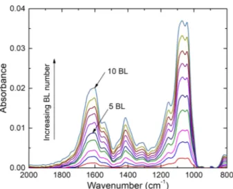
Three LbL systems were investigated: alginate/Nchitosan30, algi-nate/Pchitosan30 and alginate/Pchitosan250. FTIR spectrum was re-corded for each bilayer and for each system.Fig. 3 shows, as an ex-ample, the evolution of absorbance for the alginate/Pchitosan30 system, according to the bilayers number up to 10 bilayers.
FromFig. 3, it is possible to depict vibrations of both alginate and Pchitosan 30. For the alginate, the vibrations of the COO−carboxylate
group[24]are clearly visible: asymmetric elongation at 1594 cm−1and
symmetrical elongation at 1408 cm−1, respectively. For the
Pchi-tosan30, the two vibrations at 1656 and 1589 cm−1are attributed to
amide I and to NeH bending [38]of NH2, respectively. The main
phosphonate band is also observed at 1190 cm−1due to the elongation
of the P = O double bond[39]. The presence of this peak is due to the partial hydrolysis of phosphonic esters to phosphonic acids during the synthesis of Pchitosan30. FromFig. 3, the absorbance at 1090 cm−1
(i.e., maximum wavelength corresponding to CeOeC bonds for both the alginate and the chitosan) was used to follow the film growth. The
Fig. 1. ZP of Nchitosan30 and Pchitosan30 as a function of pH.
Fig. 2. Structure of statistical Pchitosan30 at pH = 5, containing 8% of acetylated moieties, 68–73% of amine moieties and 20–25% of amino-bisphonic acid moieties.
absorbance was plotted as a function of the bilayers number for the three LbL systems (Fig. 4). A linear increase of the absorbance is ob-served for the three systems. For 10 bilayers, the absorbance recorded for the alginate/Pchitosan250 coating is the highest. The absorbance for the alginate/Pchitosan30 is slightly higher than that of alginate/ Nchitosan30. From this result, it can be concluded that the phosphor-ylation of native chitosan slightly increased the amount of deposited chitosan.
FE-SEM cross-section observations of the wafer/chitosan films were performed for the three LbL coatings (Fig. 5). The micrographs show that the three coatings have a uniform thickness. The alginate/Nchi-tosan30 and the alginate/Pchialginate/Nchi-tosan30 LBL coatings have relatively si-milar thickness values, i.e., 200 nm and 300 nm, respectively. A higher thickness was measured for the alginate-Pchitosan250 coating, around 500 nm, in good agreement with the FTIR results.
Thus, it can be concluded that the use of phosphorylated chitosan with a high molecular weight led to a higher thickness for the LbL coatings. At pH = 5, Nchitosan30 is a cationic polymer, which will show linear conformation when assembled with the anionic alginate layer. On the other way, we showed that at pH = 5, Pchitosan30 was zwitterionic (i.e., with maximum 20–25% of anionic charge and max-imum 68–73% of cationic charge), which might lead to some coil forms due to intramolecular interactions between cationic and anionic charges. Consequently, when associated to the anionic alginate layer, a
higher amount of Pchitosan30 was deposited compared to Nchitosan30. Moreover, an increase of chitosan Mw, i.e. from 30 to 250 kg mol−1,
has an influence on the LbL growth. The thickening of the layer for Pchitosan250 can be explained by a greater entanglement of the polymer chains. As a consequence, a higher amount of Pchitosan250 was deposited, as compared to Nchitosan or Pchitosan30.
3.3. Evaluation of corrosion protection of the AA3003 by the LbL coatings
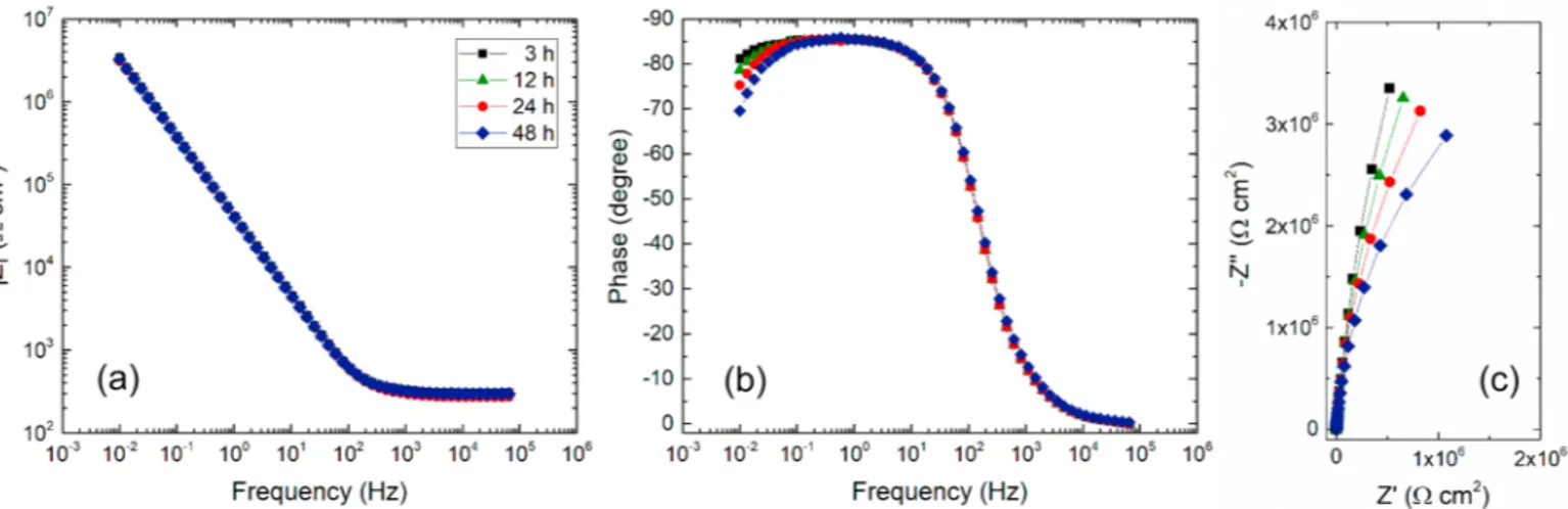
EIS measurements were performed for the AA3003 LbL coated samples as well as for the uncoated AA3003 sample. For each system, the impedance diagrams were obtained consecutively for various im-mersion times (3 h, 12 h, 24 h and 48 h) in a 0.1 M Na2SO4solution. As
an example, Fig. 6 shows the impedance diagrams obtained for the AA3003 coated with alginate/Nchitosan30 (10 BL). Independently of the immersion time, the diagrams are almost identical. They show a capacitive behavior and it can be observed that the impedance modulus and the phase angle slightly decrease at low frequency when the im-mersion time increases (more noticeable on the phase angle).
Then, for comparison, the impedance diagrams obtained after 48 h of immersion for the three LBL coatings and for the uncoated sample are presented inFig. 7.
The diagrams for the three LbL coatings are quite comparable in-dicating similar corrosion protection performance for the different systems. It can be underlined that the open circuit potential (OCP) for the different LbL systems deposited on the AA3003 was relatively si-milar (−0.90 ± 0.5 V/MSE) in agreement with the impedance results.
Fig. 3. FTIR spectra as a function of the bilayers (BL) number for the alginate/ Pchitosan30 system.
Fig. 4. Absorbance at 1090 cm−1as a function of the number of bilayers for the
three LbL systems.
Fig. 5. FE-SEM micrographs of the cross-sections of Si wafers coated with 10 bilayers for: (a) alginate/Nchitosan30, (b) alginate/Pchitosan30 and (c) algi-nate/Pchitosan250.
The OCP was slightly shifted towards more negative value by com-parison with the uncoated AA3003 sample (OCP = −0.85 ± 0.2 V/ MSE).
Despite the presence of the LbL films, visualized on the Si wafers (Fig. 5), the impedance diagrams are constituted by a single time constant. The presence of an additional time constant in the high fre-quency range, characterizing a film effect is not observed, as might be expected and as already observed for very thin organic films (20 nm) formed on a carbon steel surface[40]. The impedance response of the LbL coatings pointed out that the barrier properties were low, probably due to a porous structure of the coatings. Thus, with and without the LbL coatings, the impedance diagrams characterize the aluminum oxide film on the AA3003 surface. As can be seen inFigs. 6and7, the phase angle is always lower than −90° (maximum value around −87°) which indicates a non-ideal behavior of the AA3003/LbL coating interface. From the impedance diagrams, some parameters can be extracted: the oxide film resistance (Rox) and a constant phase element (CPE), which
accounts for the non-ideal behavior of the interface. The impedance of the CPE is given byEq. (1):
= Z j Q 1 ( ) CPE (1) With ω = 2πf and where α is related to the angle of rotation of a purely capacitive line on the complex plane plots and Q is a constant expressed in α−1cm−2sα.
In the present work, equivalent electrical circuits were not used to
extract impedance parameters because all the parameters can be gra-phically determined[41]. The Roxvalues were obtained from the
ex-trapolation at low frequency of the impedance modulus (when the phase angle decreases towards 0). The α parameter can be determined
Fig. 6. Electrochemical impedance diagrams obtained at Ecorrfor the AA3003 coated with the alginate-Nchitosan30 (10 bilayers) for different immersion times in
0.1 M Na2SO4solution in Bode (impedance modulus (a) and phase angle (b)) and Nyquist (c) coordinates
Fig. 7. Electrochemical impedance diagrams obtained at Ecorrafter 48 h of immersion in 0.1 M Na2SO4solution for the uncoated AA3003 and the three LbL coatings
(10 BL) in Bode (impedance modulus (a) and phase angle (b)) and Nyquist (c) coordinates. Table 1
Parameters obtained from the impedance data for the uncoated AA3003 and the three LbL coatings (10 BL) after different exposure times to 0.1 M Na2SO4
so-lution.
Sample Immersion time
(h) α Q (MΩ −1cm−2sα) Uncoated AA3003 3 0.94 3.2 ± 0.1 12 0.94 3.6 ± 0.2 24 0.94 4.2 ± 0.2 48 0.94 4.3 ± 0.2 AA3003/Alginate-Nchitosan30 3 0.94 4.2 ± 0.2 12 0.94 4.3 ± 0.2 24 0.94 4.3 ± 0.1 48 0.94 4.5 ± 0.1 AA3003/Alginate-Pchitosan30 3 0.93 3.7 ± 0.1 12 0.94 4.3 ± 0.1 24 0.93 4.5 ± 0.1 48 0.94 4.8 ± 0.2 AA3003/Alginate-Pchitosan250 312 0.940.94 3.7 ± 0.13.9 ± 0.1 24 0.94 4.0 ± 0.1 48 0.94 4.2 ± 0.1
108 C: � 107
a:::
·-·•·--uncoated ·· • alginate-Nchitosan30 -+- alginate-Pchitosan30 • "·.
..,,.
. --•- . · · *.. alginate-Pchitosan250 ... '*··-.:
:
�
:
:
·t
-
·· ___
,_
___
.
.
.
.
.
..
, .
.
•
♦ ♦ 105..__._ _____ _,_ __ _,_ _____ __._� 10 20 3040
50
Immersion time (h)
Fig. 8. Rox as a function of the immersion time in 0.1 M Na2SO4 solution for the uncoated AA3003 and for the three LbL coatings (10 BL).
by plotting the logarithm of the imaginary part of the impedance (Z)
with respect to the logarithm of the frequency (F.q. (2)). Q is expressed as a fonction of a and impedance data (F.q. (3)):
dlog(-Zj) a=--___,;;-dlog(f)
.
(Cl7C)
-1 Q = SIIl2
Zj(f)(21r/)« (2) (3)The a and Q values are reported in Table 1 for the different systems and for various immersion times.
� 2!'; ëii C Cil C 0 N 1-'
1/\
0.5 C 0 0.5 p 1.0 1.5 2.0Energy (keV)
Al Na 1.0 1.5 2.0Energy (keV)
{a) 2.5 (b)s
2.5The variation of Rox as a fonction of the exposure time to the Na2SO4
solution is shown in Fig. 8.
For the uncoated M3003, the Rox value decreases with increasing
immersion time. This might be attributed to the corrosion process which induces a local pH increase on the aluminum surface due to the cathodic reaction (oxygen reduction) (42). As a consequence, the native
aluminum oxide tends to dissolve (chemical reaction) when the im
mersion time increases. This assumption is in agreement with the var iation of Q vs the immersion time (Table 1). The Q value, related to the oxide film capacitance, increases with time indicating a decrease of the oxide film thickness.For the three LbL coatings, Rox slightly decreases during the first
hours of exposure to the electrolyte and then remains constant. After 48 h of immersion, the Rox values are similar for the three systems and
they are at least two orders of magnitude higher for the coated samples (108Qcm2) by comparison with the uncoated sample (5 105Qcm2),
suggesting a decrease of the active surface area by the coatings, since there is no modification of the a and Q parameters. This last result indicates that the chitosan phosphorylation did not improve the cor rosion protection of the M3003 by comparison with the native chit osan although the LbL coatings thickness was higher, in particular for the alginate-Pchitosan250, as observed by SEM on the Si wafers (Fig. 5).
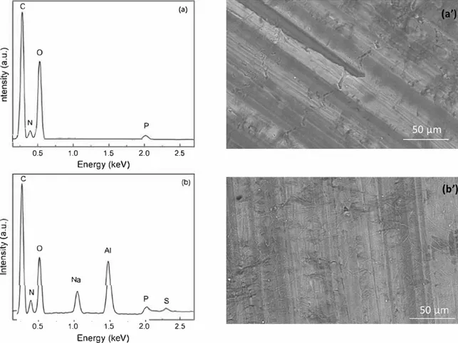
SEM-EDX analysis was performed with a low energy (5 keV) to compare the layer composition before (Fig. 9a and a') and after 48 h of immersion in the Na2SO4 solution (Fig. 9b and b'). The analysis was showed here for the alginate-Pchitosan250 LbL coating.
Before immersion (Fig. 9a and a'), the analysis reveals the presence of C, N, 0 and P peaks confirming the presence of the alginate and the Pchitosan on the M3003 surface. It is worthy to note that the Al peak is not detected, which might indicate the presence of a uniform LbL coating, as shown by the SEM observations on the Si wafers (Fig. 5).
Fig. 9. EDX analysis and SEM observations for the alginate-Pchitosan250 LbL coating: (a) and (a') before immersion and (b) and (b') after 48 h of immersion in the Na�O4 0.1 M solution.
4. Conclusions
Layer-by-Layer coatings comprising alginate and either unmodified or phosphorylated chitosan at different molecular weights were eval-uated for their potential to reduce the corrosion of an aluminum alloy 3003. First, the growing rate of the LbL coatings was determined on Si wafers by measuring the IR absorbance according to the bilayers number. The system containing phosphorylated chitosan appeared to grow faster than that with the unmodified chitosan. FE-SEM observa-tions revealed coating thicknesses between 200 nm and 500 nm ac-cording to the type of chitosan. It was found that the use of phos-phorylated chitosan at 1 wt.% and high molecular weight (250,000 g mol−1) promoted the deposition of thicker coatings. The
corrosion protection of the AA3003 was assessed by electrochemical impedance spectroscopy in a Na2SO40.1 M solution. It was shown that
the three LbL systems afforded similar corrosion protection by reducing the active surface area by comparison with the uncoated sample. Even if the EDX analysis has confirmed the presence of the coating on the metal surface, the EIS measurements revealed a limited barrier effect.
Author contributions
The manuscript was written through contributions of all authors. All authors have given approval to the final version of the manuscript. All authors contributed equally.
Funding sources
This work was financially supported by the Direction Générale de l'Armement (DGA). The authors gratefully acknowledge the DGA for this support.
References
[1] G. Malucelli, F. Bosco, J. Alongi, F. Carosio, A. Di Blasio, C. Mollea, F. Cuttica, A. Casale, Biomacromolecules as novel green flame retardant systems for textiles: an overview, RSC Adv. 4 (2014) 46024–46039.
[2] G. Malucelli, Layer-by-layer nanostructured assemblies for the fire protection of fabrics, Mater. Lett. 166 (2016) 339–342.
[3] S.I. Cordoba de Torresi, J.R. Martins Neto, M. Vidotti, F. Huguenin, Layer-by-layer
[4] V.N. Gunjkar, S.L. Patwekar, S.P. Dhage, Stimuli responsive layer by layer self-assembly a novel approachs in current drug delivery: review, World J. Pharm. Pharm. Sci. 4 (2015) 216–238.
[5] D. Volodkin, A. Skirtach, H. Moehwald, Bioapplications of light-sensitive polymer films and capsules assembled using the layer-by-layer technique, Polym. Int. 61 (2012) 673–679.
[6] N. Estillore, W. Knoll, R. Advincula, Functional layer-by-layer polyelectrolytes: assembly strategies, characterization, and selected applications, Ionic Interactions in Natural and Synthetic Macromolecules 17 (2012), pp. 643–682.
[7] D.V. Andreeva, E.V. Skorb, Multi-layer smart coatings for corrosion protection of aluminium alloys and steel, Woodhead Publ. Ser. Met. Surf. Eng. 64 (2014) 307–327.
[8] G. Decher, Fuzzy nanoassemblies: toward layered polymeric multicomposites, Science 277 (1997) 1232–1237.
[9] R.K. Iler, Multilayers of colloidal particles, J. Colloid Interface Sci. 21 (1966) 569–594.
[10] P. Berndt, K. Kurihara, T. Kunitake, Adsorption of poly(styrenesulfonate) onto an ammonium monolayer on mica: a surface forces study, Langmuir 8 (1992) 2486–2490.
[11] S.A. Umoren, U.M. Eduok, Application of carbohydrate polymers as corrosion in-hibitors for metal substrates in different media: a review, Carbohydr. Polym. 140 (2016) 314–341.
[12] S.K. Kim, Chitin, Chitosan, Oligosaccharides and Their Derivatives: Biological Activities and Applications, 1st ed, CRC Press, Boca Raton, 2010.
[13] R.A.A. Muzzarelli, Chitin, Pergamon Press, Oxford, 1977.
[14] I. Tsigos, A. Martinou, D. Kafetzopoulos, V. Bouriotis, Chitin deacetylases: new, versatile tools in biotechnology, Trends Biotechnol. 18 (2000) 305–312. [15] P.J. VandeVord, H.W.T. Matthew, S.P. DeSilva, L. Mayton, B. Wu, P.H. Wooley,
Evaluation of the biocompatibility of a chitosan scaffold in mice, J. Biomed. Mater. Res. 59 (2002) 585–590.
[16] M. Rinaudo, Chitin and chitosan: properties and applications, Prog. Polym. Sci. 31 (2006) 603–632.
[17] S. Tokura, K. Ueno, S. Miyazaki, N. Nishi, Molecular Weight Dependent Antimicrobial Activity By Chitosan, New Macromolecular Architecture and Functions, Springer, Berlin Heidelberg, 1996.
[18] P.K. Dutta, J. Dutta, V.S. Tripathi, Chitin and chitosan: chemistry, properties and applications, J. Sci. Ind. Res. 63 (2004) 20–31.
[19] J. Nunthanid, S. Puttipipatkhachorn, K. Yamamoto, G.E. Peck, Physical properties and molecular behavior of chitosan films, Drug Dev. Ind. Pharm. 27 (2001) 143–157.
[20] H. Grasdalen, High-field, 1H-NMR spectroscopy of alginate: sequential structure and linkage conformations, Carbohydr. Res. 118 (1983) 255–260.
[21] S.G. Caridade, C. Monge, F. Gilde, T. Boudou, J.F. Mano, C. Picart, Free-standing polyelectrolyte membranes made of chitosan and alginate, Biomacromolecules 14 (2013) 1653–1660.
[22] H. Gao, M. Zhang, J. Zhao, L. Gao, M. Li, In vitro and in vivo degradation and mechanical properties of ZEK100 magnesium alloy coated with alginate, chitosan and mechano-growth factor, Mater. Sci. Eng. 63 (2016) 450–461.
[23] M. George, T.E. Abraham, Polyionic hydrocolloids for the intestinal delivery of protein drugs: alginate and chitosan–a review, J. Controlled Release 114 (2006) 1–14.
[24] G. Lawrie, I. Keen, B. Drew, A. Chandler-Temple, L. Rintoul, P. Fredericks, L. Grøndahl, Interactions between alginate and chitosan biopolymers characterized using FTIR and XPS, Biomacromolecules 8 (2007) 2533–2541.
[25] C. Brondino, B. Boutevin, J.-P. Parisi, J. Schrynemackers, Adhesive properties onto galvanized steel plates of grafted poly(vinylidene fluoride) powders with phos-phonated acrylates, J. Appl. Polym. Sci. 72 (1999) 611–620.
[26] E. Kálmán, F.H. Kármán, J. Telegdi, B. Várhegyi, J. Balla, T. Kiss, Inhibition effi-ciency of N-containing carboxylic and carboxy-phosphonic acids, Corros. Sci. 35 (1993) 1477–1482.
[27] X.H. To, N. Pebere, N. Pelaprat, B. Boutevin, Y. Hervaud, A corrosion-protective film formed on a carbon steel by an organic phosphonate, Corros. Sci. 39 (1997) 1925–1934.
[28] I. Maege, E. Jaehne, A. Henke, H.-J.P. Adler, C. Bram, C. Jung, M. Stratmann, Self-assembling adhesion promoters for corrosion resistant metal polymer interfaces, Prog. Org. Coat. 34 (1998) 1–12.
[29] F. Millet, R. Auvergne, S. Caillol, G. David, A. Manseri, N. Pébère, Improvement of corrosion protection of steel by incorporation of a new phosphonated fatty acid in a phosphorus-containing polymer coating obtained by UV curing, Prog. Org. Coat. 77 (2014) 285–291.
[30] C. Coquery, C. Negrell, N. Caussé, N. Pébère, G. David, Synthesis of new high molecular weight phosphorylated chitosans for improving corrosion protection, Pure Appl. Chem. 91 (3) (2019) 509–521.
[31] L. Liu, Y. Pan, Z. Wang, Y. Hou, Z. Gui, Y. Hu, Layer-by-layer assembly of hypo-phosphorous acid-modified chitosan based coating for flame-retardant poly-ester–cotton blends, Ind. Eng. Chem. Res. 56 (34) (2017) 9429–9436. [32] F. Carosio, J. Alongi, Ultra-fast layer-by-layer approach for depositing flame
re-tardant coatings on flexible PU foams within seconds, ACS Appl. Mater. Interfaces 8 (10) (2016) 6315–6319.
[33] F. Carosio, C. Negrell-Guirao, J. Alongi, G. David, G. Camino, All-polymer layer by layer coating as efficient solution to polyurethane foam flame retardancy, Eur. Polym. J. 70 (2015) 94–103.
[34] V. Vassileva, E.M. Georgiev, K. Troev, D.M. Roundhill, Dealkylation of phosphorus-containing alkylammonium salts formed by the interaction of phosphonic,
After immersion in the Na2SO4 solution (Fig. 9b and b’), the C, N, O and
P peaks are still visible, showing that the LbL coating is always present on the AA3003 surface. After immersion, Al is detected which suggests that the LbL coating was damaged during the immersion. In addition, the Na and S peaks are observed, indicating the presence of sodium sulfate (from the electrolyte) in the LbL coating. The EDX analyses confirmed that a LBL coating was formed on the AA3003 surface but the barrier effect was limited (penetration of the electrolyte and presence of the Al peak).
EIS data and EDX analysis revealed that chitosan/alginate LBL coatings allowed the AA3003 surface to be protected through a barrier effect, w hich d ecreased t he a ctive s urface a rea i n c ontact w ith the electrolyte. Nevertheless, during exposure to the Na2SO4 solution, the
barrier effect was limited, as shown from the impedance results, despite the presence of the coating, as proved by the EDX analysis. The limited barrier effect could be attributed to a swelling of the LBL coating, and to a partial solubility of the Nchitosan and Pchitosan in the aqueous so-lution.
Furthermore, the phosphonic acid moieties grafted onto chitosan allowed higher coating thicknesses to be reached compared to native chitosan (Fig. 5), but similar electrochemical behaviors were observed (Fig. 8 and Table 1). One way to improve the barrier properties of such coatings might be to perform an additional cross-linking, after the LbL deposition. Or, the bilayer should be more hydrophobic. In this case, chitosan chemical modification should be done prior to perform the LbL deposition.
assembly of electrochromic materials: on the efficient method for immobilisation of nanomaterials, Electrochromic Materials and Devices 12 (2015), pp. 337–361.
methanephosphonic and phosphoric acid esters with diamines, Phosphorus Sulfur Silicon Relat. Elem. 92 (1994) 101–107.
[35] P.G. Falireas, C. Negrell, G. David, Synthesis and aqueous solution properties of an amino bisphosphonate methacrylate homopolymer via RAFT polymerization, Polymers 10 (2018) 711–723.
[36] K.I. Draget, G. Skjåk Bræk, O. Smidsrød, Alginic acid gels: the effect of alginate chemical composition and molecular weight, Carbohydr. Polym. 25 (1994) 31–38. [37] G. Laufer, C. Kirkland, A.A. Cain, J.C. Grunlan, Clay–chitosan nanobrick walls:
completely renewable gas barrier and flame-retardant nanocoatings, ACS Appl. Mater. Interfaces 4 (3) (2012) 1643–1649.
[38] B. Smitha, S. Sridhar, A.A. Khan, Chitosan-sodium alginate polyion complexes as fuel cell membranes, Eur. Polym. J. 41 (2005) 1859–1866.
[39] N. Illy, G. Couture, R. Auvergne, S. Caillol, G. David, B. Boutevin, New prospects for the synthesis of N-alkyl phosphonate/phosphonic acid-bearing oligo-chitosan, RSC Adv. 4 (2014) 24042–24052.
[40] J. Baux, N. Causse, J. Esvan, S. Delaunay, J. Tireau, M. Roy, D. You, N. Pebere, Impedance analysis of film-forming amines for the corrosion protection of a carbon steel, Electrochim. Acta 283 (2018) 699–707.
[41] M. Orazem, N. Pébère, B. Tribollet, Enhanced graphical representation of electro-chemical impedance data, J. Electrochem. Soc. 153 (4) (2006) B129–B136. [42] J.B. Jorcin, C. Blanc, N. Pébère, B. Tribollet, V. Vivier, Galvanic coupling between
pure copper and pure aluminum : experimental approach and mathematical model, J. Electrochem. Soc. 155 (1) (2008) C46–C51.