Technique de réutilisation de longueur d’onde optique
dans des applications RoF basée sur les RSOA pour
des communications bidirectionnelles OOK et OFDM
Mémoire
Kim Lefebvre
Maîtrise en génie électrique - avec mémoire
Maître ès sciences (M. Sc.)
Technique de réutilisation de longueur d’onde optique
dans des applications RoF basée sur les RSOA pour
des communications bidirectionnelles OOK et OFDM
Mémoire
Kim Lefebvre
Sous la direction de :
Résumé
Le présent mémoire vise le domaine des télécommunications optiques et de la radio sur fibre (RoF). Il a pour objectif de proposer une technique de réutilisation de longueur d’onde optique afin de transmettre un signal sans-fil 802.11a en amont et un signal numérique OOK en aval dans la même bande passante. Cette technique se base sur les amplificateurs à semiconducteur réfléchissant (RSOA). Ce composant permet l’effacement du signal numérique arrivant par la saturation de son amplificateur qui sera ensuite réutilisé comme modulateur de fréquence radio (RF) pour retourner un signal sans-fil 802.11a dans une bande pouvant chevaucher le signal effacé.
Par l’entremise des articles qui sont publiés et relatés dans ce mémoire, une étude exhaustive de la technique de saturation du RSOA aux fins de re-modulation ainsi que des performances obtenues en laboratoire y est présentée. Trois formats de modulations QPSK, 16QAM et 64QAM y seront testés. L’évaluation des performances sera réalisée à l’aide des paramètres suivants : le taux d’erreur binaire (BER), le facteur de qualité (Q), la norme du vecteur d’erreur (EVM), la distance de propagation atteinte dans la fibre, la vitesse de transmission et l’indice de modulation (MI).
Cette technique peut être utilisée pour un signal sans-fil 802.11a d’une antenne jusqu’à une centrale par fibre optique, et ce, jusqu’à 80 km avec un format de modulation QPSK. Il est également possible de transmettre du 64QAM jusqu’à 40 km tout en gardant une bonne performance en sens opposé.
Il a été également possible de conclure expérimentalement qu’il est possible de multiplexer plusieurs signaux sans-fil sur 20 km dans la bande RF du RSOA en coexistence avec un signal numérique en sens opposé. Cela ouvre des portes sur de nouvelles recherches d’architectures où les coûts, la consommation de puissance et le traitement de signaux sont plus centralisés et à bas prix.
iii
Table des matières
Résumé ... ii
Table des matières ... iii
Liste des figures ... v
Liste des abréviations, sigles, acronymes ... vi
Remerciements ... xi
Avant-propos ... xii
Introduction ... 1
Accroissement de la bande passante sans fil ... 1
L’optique pour les réseaux sans fil ... 2
La radio sur fibre pour le Fronthaul ... 3
Réseau optique passif PON ... 5
Amplificateurs à semi-conducteur réfléchissant en radio sur fibre ... 6
Organisation du mémoire ... 7
Chapitre 1 Enabling In-band Bidirectional OFDM-Uplink and OOK-Downlink Transmission in Long-reach RSOA-based WDM-PON Systems ... 8
1.1 Résumé ... 8
1.2 Abstract ... 8
1.3 Introduction ... 9
1.4 Impact of Downlink Operation Point on Quality of RSOA Erasure and OOK-DL Signal ... 10
1.5 Individual Effect of Vbias and VRF on DL/UL Performance ... 14
1.6 Transmission Results and Discussion ... 16
1.7 Conclusion ... 18
Chapter 2 Multi-service OFDM Uplink Transmission in Full-Duplex FTTx Systems Using RSOA-based WDM-PON Architecture ... 19
2.1 Résumé ... 19
2.2 Abstract ... 19
2.3 Introduction ... 19
2.4 Working Principle and Experimental Setup ... 20
2.5 Results and Remarks ... 22
2.6 Conclusion ... 23
2.7 Acknowledgements ... 23
Conclusion ... 24
Annexe A Full-duplex in-band OOK-Downlink/OFDM-Uplink transmitted over 40 km of SSMF in RSOA-based radio-over-fiber system ... 26
A.2 Abstract ... 26
A.3 Introduction ... 26
A.4 Experimental Setup ... 27
A.5 Results and Discussion ... 28
A.6 Conclusion ... 29
A.7 Acknowledgements ... 29
Annexe B Downstream modulation index tuning to enable full-duplex OOK-DL/OFDM-UL transmission in RSOA-based Radio-over-Fiber system ... 30
B.1 Résumé ... 30
B.2 Abstract ... 30
B.3 Introduction ... 31
B.4 Working Principle ... 32
B.5 Experiment, Results and Discussion ... 34
B.6 Conclusion ... 36
v
Liste des figures
Figure 1 : Prévision de l’augmentation du trafic global par type d’appareils de 2017 à 2022 selon Cisco VNI [1].
... 1
Figure 2 : Exemple de réseau optique mobile... 3
Figure 3 : Concept de radio sur fibre numérique (D-RoF). ... 4
Figure 4 : Concept de radio sur fibre (RoF). ... 4
Figure 5 : Diverses configurations de PONs. ... 5
Figure 6 : RSOA dans les applications RoF. ... 6
Figure 7: (Left) MI compression in saturated SOA. (Right) experimental setup to investigate effect of OOK-DL MI on received Q-factor and noise variance of reflected carrier. ... 11
Figure 8: (Left) noise standard deviation on the reflected carrier as a function of Vbias and VRF driving the MZM: B2B, (right) after 20 km of SSMF. Dotted lines are Q-factor = 6 boundary. Vbias and VRF are normalized to Vπ. ... 12
Figure 9: (Left) MI compression in saturated RSOA. (Right) electrical spectra of incoming OOK signal to the RSOA and its suppressed reflection. ... 13
Figure 10: Experimental setup investigating the effect of MZM drive parameters on DL/UL performance and transmission. ... 14
Figure 11: (Left) Q-factor of OOK-DL signal and EVM of OFDM-UL signal as a function of VRF. (Right) EVM of OFDM-UL signal as a function of Vbias when OOK-DL Q-factor = 6.3 (solid), 12 (dotted). ... 15
Figure 12: (Red) spectra of OFDM-UL signal over the reflected carrier when OOK-DL is OFF, (black) ON and suppressed, (left) for B2B, and (right) after 20 km of SMMF. Overlapped figures are the zoomed-in views of OFDM-UL signal. ... 16
Figure 13: (Left) MI of the OOK-DL to maintain error-free performance, (inset) OOK-DL eye-diagram; (middle) EVM/BER of WiFi OFDM-UL signal using different modulation modes. Example constellations for QPSK (60, 70 km), 16QAM (40, 60 km), 64QAM (20, 40 km). ... 17
Figure 14: RF architecture supporting multiple receiving antennas (combined with figure 10). ... 20
Figure 15: Spectrum of UL signal in the presence of OOK-DL signal (left); RSOA’s frequency response and measured SNR of UL signal (right). ... 22
Figure 16: EVM of received UL WiFi services (left); EVM tolerance with channel spacing (right). ... 23
Figure 17: Modulation index of the OOK-DL for error-free performance. ... 28
Figure 18: EVM/BER of WiFi OFDM-UL signal in different modes. ... 29
Figure 19: Standard deviation of residual modulation on reflected optical carrier as a function of Vbias and VRF. ... 33
Figure 20: Q-factor of OOK-DL signal and EVM of OFDM-UL signal as a function of VRF. ... 35
Liste des abréviations, sigles, acronymes
16QAM 16 state Quadrature Amplitude Modulation
3GPP 3rd Generation Partnership Project
64QAM 64 state Quadrature Amplitude Modulation
802.11a WiFi communication standard
ADC Analog to Digital Converter
Amp Amplifier
AP Access Point
APC Angled Physical Contact
ASE Amplified Spontaneous Emission
B2B Back-to-Back
BBU Base Band Unit
BER Bit Error Rate
BERT Bit Error Rate Tester
BPG Bit Pattern Generator
BPF Band Pass Filter
BPSK Binary Phase Shift Keying
CC Convolution Code
CO Central Office
vii
CPRI Common Public Radio Interface
CW Continuous Wave
DAC Digital to Analog Converter
Demux Demultiplexing
DL Downlink
D-RoF Digital Radio over Fibre
DSP Digital Signal Processing
E/O Electro-optic
EML Electro-absorption Modulated Integrated Laser
ER Extinction Ratio
EVM Error Vector Magnitude
FDD Frequency Division Duplexing
FEC Forward Error Correction
FTTA Fibre-To-The-Antenna
FTTC Fibre-To-The-Curb
FTTH Fibre-To-The-Home
FTTx Fibre-To-The-x
IEEE Institute of Electrical and Electronics Engineers
IF Intermediate Frequency
LNA Low Noise Amplifier
LTE Long Term Evolution
MAC Media Access Control
MI Modulation Index
MIMO Multiple Inputs Multiple Outputs
MPLS Multiprotocol Label Switching
Mux Multiplexing
MZM Mach-Zehnder Modulator
NRZ Non-Return-to-Zero
NSERC Natural Science and Engineering Council of Canada
O/E Optoelectronic
OFDM Orthogonal Frequency Division Multiplexing
ONT Optical Network Terminal
ONU Optical Network Unit
OOK On/Off Keying
OSC Oscilloscope
PC Physical Contact
PC Polarization Controller
Pin Input Power
PIN Positive Intrinsic Negative
PL Packed Length
ix
PMD Polarization Mode Dispersion
PON Passive Optical Network
Pout Output Power
PRBS Pseudo-Random Bit Sequence
Q Quality factor
QPSK Quadrature Phase-Shift Keying
RAN Remote Antenna Unit
RF Radio Frequency
RoF Radio over Fibre
RRH Remote Radio Head
RSOA Reflective Semiconductor Optical Amplifier
RTO Real-Time Oscilloscope
Rx Receive
SAVI Smart Applications on Virtual Infrastructure
SMF Single Mode Fibre
SOA Semiconductor Optical Amplifier
SPM Self-Phase Modulation
SSMF Standard Single Mode Fibre
Tx Transmit
UE User End
Vbias Composante DC du signal
VNI Visual Networking Index
VRF Composante AC du signal
VSG Vector Signal Generator
Vπ
Différence de potentiel requise au modulateur pour passer d’une amplitude maximale à minimale. Communément nommé « Half-Wave Voltage »
WDM Wavelength Division Multiplexing
WiFi Wireless Fidelity
XPM Cross-Phase Modulation
xi
Remerciements
La réalisation de ce mémoire a été possible grâce à plusieurs personnes à qui je voudrais témoigner toute ma reconnaissance. M’ayant épaulé durant cette étape de ma vie, ces personnes ont contribué à façonner la personne que je suis maintenant sur le plan professionnel.
Je veux tout d’abord adresser toute ma gratitude à la directrice de recherche, Leslie A. Rusch, pour sa patience, sa disponibilité, ses judicieux conseils et l’implication dont elle a fait preuve dans ce projet à différents niveaux.
Je désire aussi remercier le chercheur postdoctoral An T. Nguyen qui a mis à contribution toutes ses connaissances dans ce projet. Il m’a aidé dans l’établissement du projet à tous les niveaux afin que la recherche et les tests en laboratoire se déroulent sans anicroche. Sa grande maîtrise des systèmes optiques m’a permis d’apprendre rapidement les rouages des tests en laboratoire afin de compléter ce projet.
Je veux également remercier Dr. Mehrdad Mirshafiei qui, lors de mes débuts dans la recherche d’un sujet, m’a grandement aidé en me prodiguant de judicieux conseils dans la première année. Ces discussions m’ont proprement orienté et m’ont permis d’avoir une meilleure compréhension des systèmes de télécommunications optiques.
Pour terminer, je veux remercier le Dr. Chul-Soo Park qui m’a aidé lors des tests en laboratoire lorsque j’ai eu besoin de remplacer, de réparer ou d’avoir une meilleure compréhension des pièces d’équipements. Cela m’a permis d’avancer plus rapidement dans le projet.
Avant-propos
Ce projet de recherche a été soumis à l’Université Laval dans le cadre d’un programme de maîtrise avec mémoire et quatre cours. Ce projet de recherche a été réalisé sous la supervision de Leslie Ann Rusch qui est professeure à l’Université Laval au département de génie électrique et de génie informatique et également chercheure au Centre d’Optique Photonique de l’Université Laval (COPL). Kim Lefebvre a effectué le travail conjointement avec An Truong Nguyen. Le projet comporte donc deux premiers coauteurs et, en raison de la répartition égalitaire des tâches, il y a eu une alternance des noms pour le premier auteur lors de la parution des articles. Les chapitres 1 et 2 sont des copies reformatées des articles qui ont été publiés.
Le chapitre 1 parlera de l’article de journal suivant :
« Enabling In-Band Bidirectional OFDM-Uplink and OOK-Downlink Transmission in Long-Reach RSOA-Based WDM-PON Systems » (Kim Lefebvre, An T. Nguyen, Leslie A. Rusch, accepté et publié dans Journal of Lightwave Technology, Volume: 32 , Issue: 20, paru le 15 octobre 2014 où la première publication fut le 17 juin 2014)
Cet article est un regroupement des deux articles de conférences suivants qui seront en annexe:
« Modulation index tuning to enable full-duplex OOK-DL/OFDM-UL transmission in RSOA-based Radio-over-Fiber system » (Kim Lefebvre, An T. Nguyen, Leslie A. Rusch, accepté et publié dans 2013 IEEE International Topical Meeting on Microwave Photonics (MWP), Conférence du 28 au 31 octobre 2013, Accessible via IEEE Xplore depuis le 27 janvier 2014)
et
« Full-duplex in-band OOK-Downlink/OFDM-Uplink transmitted over 40km of SSMF in RSOA-based radio-over-fiber system » (Kim Lefebvre, An T. Nguyen, Leslie A. Rusch, accepté et publié dans 2013 IEEE Photonics Conference, Conférence du 8 au 12 septembre 2013, Accessible via IEEE Xplore depuis le 7 novembre 2013).
Le sujet de recherche a été défini par le professeur Leslie A. Rusch. An T. Nguyen et moi-même avons proposé l’idée d’utiliser des RSOA dans les applications RoF sans-fil analogique. La méthodologie expérimentale a été établie par An T. Nguyen et, avec son aide, j’ai été responsable du montage, des tests et des mesures. Pour le signal sans-fil à transporter optiquement, An T. Nguyen s’est chargé de la conception du signal du type 802.11b avec MATLAB. De mon côté, je me suis chargé de son traitement hors ligne avec
xiii
MATLAB lors des prises de mesures expérimentales. J’ai également contribué à la rédaction des articles, avec An T. Nguyen et Leslie A Rusch.
Le chapitre 2 parlera de l’article de conférence OFC suivant :
« Multi-service OFDM Uplink Transmission in Full-Duplex FTTx Systems Using RSOA-based WDM-PON Architecture » (An T. Nguyen, Kim Lefebvre et Leslie A. Rusch, accepté et publié dans OFC 2014, Conférence du 9 au 13 mars 2014 à San Francisco, CA, USA. Accessible via IEEE Xplore depuis le 28 août 2014).
Le projet comporte donc deux premiers coauteurs et, en raison de la répartition égalitaire des tâches, il y a eu une alternance des noms pour le premier auteur lors de la parution des articles. Le sujet de recherche a été défini par le professeur Leslie A. Rusch et est dans la même continuité que les premiers articles publiés, le but ultime étant de démontrer la viabilité de la solution RoF basée sur les RSOA pour des communications bidirectionnelles OFDM. Cet article est la suite des démonstrations du chapitre 1 (soit de concept et de caractérisation). La méthodologie expérimentale a été établie par An T. Nguyen et, avec son aide, j’ai été responsable des tests et des mesures. Encore une fois, An T. Nguyen s’est chargé de la conception du signal du type 802.11b avec MATLAB, tandis que je me suis chargé de son traitement hors ligne avec MATLAB lors des prises de mesures expérimentales. La rédaction a été accomplie avec An T. Nguyen et Leslie A Rusch.
Introduction
Accroissement de la bande passante sans fil
La demande croissante en bande passante pour les signaux sans fil ne cesse de croître et ne semble pas avoir de limites. En regardant l’historique du trafic internet du Tableau 1, provenant du projet de Cisco Visual Networking Index (VNI) [1], nous pouvons constater que, depuis 30 ans, le trafic global d’Internet augmente de façon considérable et de manière exponentielle.
Année Traffic Global d’Internet
1992 100 GB par jour 1997 100 GB par heure 2002 100 GB par seconde 2007 2 000 GB par seconde 2017 46 600 GB par seconde 2022 150 700 GB par seconde
Tableau 1: Historique des prévisions de Cisco VNI [1].
Cette augmentation du trafic a lieu tant au niveau des lignes fixes que des appareils mobiles. Cependant, nous avons pu constater par nous-même que, depuis l’arrivée des téléphones intelligents, la demandes provenant des appareils mobiles tend à croître en raison de l’avènement des médias sociaux et de la haute définition. Comme le montre la figure 1 provenant du même projet VNI [1] que le tableau 1, si la tendance se maintient, les appareils mobiles pourraient occuper jusqu’à 50% du trafic internet dans un horizon assez rapproché.
2
Durant le début des années 2000 jusqu’à aujourd’hui, les protocoles sans fil communément nommés Wireless Fidelity (WiFi) se sont développés dans le but de répondre à la demande croissante en bande passante. De la même manière, la téléphonie mobile a connu une évolution en enchaînant successivement, au fil des années, divers protocoles afin de répondre à la demande du marché. Dans les années où le projet de recherche a débuté, le protocole 3G était la norme. Le Long Term Evolution (LTE) s’est également développé et a commencé à être standardisé avec l’arrivée du 3rd Generation Parthnership Project (3GPP) [2]. Dans le cas des réseaux sans-fil, le protocole 802.11n était tout nouveau. Les normes WiFi étaient le 802.11b/a/g pouvant aller jusqu’à 54Mbits/s. Ces normes ont défini le marché durant plus d’une décennie.
L’optique pour les réseaux sans fil
L’augmentation des utilisateurs et de la bande passante requise a rapidement forcé l’utilisation d’un nouveau matériau pour le transport de l’information. La fibre optique est devenue le seul moyen efficace pour transporter un maximum d’information sur une grande distance. Alors qu’un câble de cuivre peut atteindre des taux de transport de l’ordre du gigabit par seconde sur moins d’un kilomètre, la fibre optique peut atteindre des taux de quelques térabits par seconde sur une distance pouvant aller jusqu’à cent kilomètres sans amplification et sans régénération.
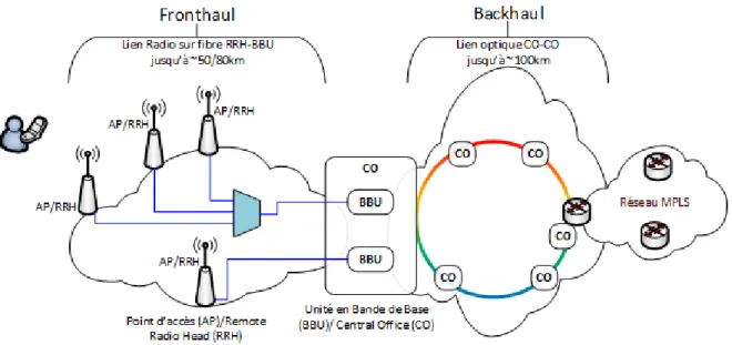
À la figure 2, nous avons un exemple d’architecture où l’optique est intégrée tant au Fronthaul qu’au Backhaul. Pour le Fronthaul qui représente la portion entre le point d’accès (AP) des clients et les unités en bandes de bases (BBU) qui traitent le signal, l’utilisation de l’optique permet une meilleure centralisation de la complexité jusqu’aux centrales (CO) ainsi qu’une extension de la distance entre les AP/RRH et les BBU. Dans le cas où les BBU se retrouvent au CO, le distributeur de service se trouverait donc à posséder un espace dans le CO, ce qui serait également le cas de la compagnie ou du consortium détenant le Backhaul. Pour le Backhaul qui représente les liens CO-CO et CO-BBU lorsqu’ils ne sont pas localisés au même endroit, l’utilisation de l’optique permet une extension de la distance ainsi qu’une augmentation accrue de la bande passante.
Figure 2 : Exemple de réseau optique mobile.
La radio sur fibre pour le Fronthaul
Le concept de radio sur fibre (RoF) existe depuis très longtemps. Nous pouvons remonter jusqu’en 1984 aux États-Unis où les militaires de la division « Electronics Division of the TRW Electro Optics Research Center » en Californie on mené des recherches sur ce concept [3-5]. Très simple, à la base, le RoF permet d’acheminer directement un signal de fréquence radio (RF) à la fibre optique en l’appliquant directement au modulateur optique sans l’utilisation de la bande de base. Par la suite, le signal optique modulé peut être acheminé au BBU pour le traitement du signal. Le concept RoF s’applique donc au Fronthaul entre les liens AP-BBU et RRH-BBU. Ce concept est également applicable aux macro-cellules jusqu’aux femto-cellules.
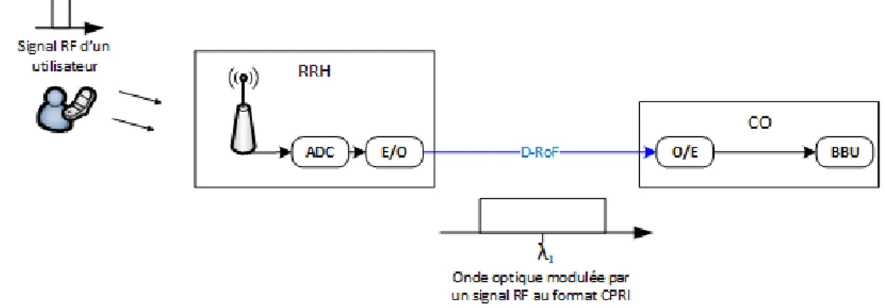
Dans le concept de radio sur fibre, il y a deux possibilités pour acheminer l’information au BBU. La première méthode est la radio sur fibre numérique (D-RoF). Comme le montre la figure 3, un signal RF est émis par un utilisateur et est capté par une antenne à un point d’accès. Ensuite, le signal RF est numérisé par le bloc convertisseur analogique à numérique (ADC) pour ensuite répondre à un standard de communication optique, comme le Common Public Radio Interface (CPRI), puis converti au bloc électro-optique (E/O) pour être acheminé au CO où le signal sera démodulé et analysé [6] et [7]. Il est à noter que par souci de simplicité, une seule des deux directions est montrée à la figure 3. L’utilisation du D-RoF permet donc de centraliser le traitement de l’information en repoussant les BBU au CO ou encore d’avoir un bassin de BBU (Base Station ou BS) à un point intermédiaire entre les RRH et le CO.
4
Figure 3 : Concept de radio sur fibre numérique (D-RoF).
La seconde méthode est la radio sur fibre analogique (RoF). Cette méthode sera celle utilisée lors de la présente recherche. Contrairement au D-RoF, le RoF achemine le signal RF sans l’utilisation de protocole intermédiaire comme le CPRI. Comme le montre la figure 4, l’option RoF fait fi des blocs ADC et DAC aux RRH en les repoussant au BBU. Il est à noter que par souci de simplicité, une seule des deux directions est montrée dans la figure 4. Dans un déploiement de grande envergure, la centralisation de chaque élément permet de diminuer le coût des RRH à tous les niveaux.
Réseau optique passif PON
Le réseau optique passif (PON) est un type de réseau qui se déploie sur des distances métropolitaines. Il peut être utilisé au Backhaul et au Fronthaul. Dans ce type de réseau, toutes les composantes sont passives. Le PON ne peut pas être utilisé sur une grande distance étant donné l’absence d’amplification. Pour desservir des utilisateurs sur des distances métropolitaines, le PON est un candidat idéal car les distances sont généralement inférieures à 100 km [8].
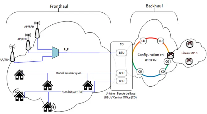
La figure 5 montre différents types de configurations pour les réseaux PON. Dépendamment du cas précis, une architecture peut être privilégiée pour diverses raisons telles que le coût, la complexité de ses unités à distances, les RRH, la consommation d’énergie et la robustesse.
Figure 5 : Diverses configurations de PONs.
Le réseau PON est une solution versatile, il peut supporter les applications Fiber To The Antenna (FTTA) où plusieurs antennes peuvent être multiplexées afin d’acheminer leur signal radio au CO. Il est aussi commun d’avoir recours au PON pour acheminer les données numériques du CO aux maisons comme dans les réseaux Fibre To The Home (FTTH) et Fibre to the Curb (FTTC).
De plus, une hybridation de signaux numériques et analogiques est aussi possible afin de fournir un accès aux données numériques ainsi qu’une couverture radio comme dans les bâtiments corporatifs et les centres d’achats. Dans cette recherche, nous allons porter notre attention sur des solutions compatibles avec les réseaux PON. La technique développée profitera de la propagation des deux types de signaux, numériques et analogiques, dans une même fibre et de l’utilisation de la composante RSOA pour établir des
6
communications bidirectionnelles analogiques et numériques à moindre coût avec un maximum de centralisation.
Amplificateurs à semi-conducteur réfléchissant en radio sur fibre
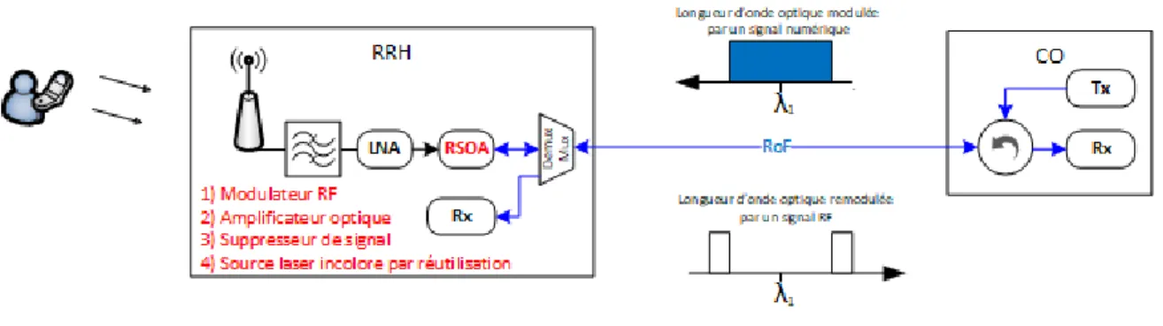
L’amplificateur à semi-conducteur réfléchissant (RSOA) est la composante principale de la recherche. Comme le montre la figure 6, elle permet l’amplification d’un signal optique pour le réfléchir et le renvoyer en direction inverse. Le RSOA n’a donc pas de source laser et est incolore. Il fonctionne par amplification de la longueur d’onde optique envoyée par le CO en autant qu’elle soit dans sa bande de gain. Le RSOA sert d’amplificateur, de suppresseur de signal en utilisant proprement ces conditions de saturations pour provoquer une compression du gain, de source laser par réutilisation de longueur d’onde et de modulateur RF. Il est donc un excellent choix pour minimiser la complexité aux RRH.
Figure 6 : RSOA dans les applications RoF.
Dans cette optique de recherche, des solutions RoF utilisant le multiplexage fréquentiel avec les réseaux optiques passifs (WDM-PON) basés sur les RSOA ont été réalisées [9-10-11]. Dans ces recherches, Le RSOA a été utilisé pour transmettre un signal radio BPSK à 6 GHz jusqu’à une distance de 40 km. Il a également été utilisé afin de démontrer une communication bidirectionnelle de 1 Gbits/s de signaux On Off Keying (OOK) jusqu’à 50 km dans une architecture WDM-RoF. Dans un autre cas, avec l’utilisation de signaux OOK, des distances de l’ordre de 25 km ont été atteintes.
Un des grands défis de l’utilisation du RSOA dans le concept de WDM-RoF est de minimiser les interférences entre le signal arrivant du CO (DL) et le signal de retour (UL). Utilisant la même fibre pour se propager dans les deux sens, avec la même longueur d’onde optique, ces signaux RF sont donc très sensibles aux non-linéarités (SPM, XPM, PDL, PMD). Les recherches dans la littérature sont principalement concentrées sur l’établissement de communications bidirectionnelles RF numériques OOK seulement. Afin d’étendre le concept de RoF basé sur les RSOA à la réalité de 2011 jusqu’à 2019, les protocoles sans fil LTE, 5G et la norme WiFi qui sont analogiques doivent être pris en considération.
Organisation du mémoire
En utilisant le concept RoF basé sur les RSOA, nous cherchons à étendre son champ d’utilité en prouvant qu’il est possible de faire coexister les protocoles analogiques sans fil avec des signaux numériques OOK. Nous allons démontrer qu’il est possible de développer une technique de compression du gain optique optimisée, au RSOA, afin de supprimer un signal numérique OOK arrivant pour réutiliser la même source laser en sens inverse. De cette manière, nous allons introduire le support des signaux analogique pour la radio sur fibre, et ce, de concert avec les signaux numériques.
Le premier chapitre est une copie d’un article publié d’une partie du travail de recherche. Il sera consacré à la preuve de concept de la coexistence d’un signal OOK-DL et d’un signal WiFi-UL sous une architecture RoF basée sur les RSOA. À l’aide d’une technique de modulation appropriée au signal OOK-DL localisé au BBU, il est possible de saturer le RSOA qui est situé au RRH et de l’utiliser comme suppresseur de signal. Par la suite, ce même RSOA va servir de modulateur à un signal RF analogique pour le retourner au BBU sous la même longueur d’onde. Cette technique de saturation sera décrite et expérimentée afin de montrer les meilleures performances en termes de distance de propagation, de BER, de facteur de qualité Q et en termes de format de modulation OFDM. Afin de mieux détailler la technique de saturation du RSOA, une étude sur le bruit résiduel post-suppression du signal numérique OOK-DL, au RSOA, sera réalisée. Il sera donc possible de bien comprendre les conditions nécessaires pour la validité du concept RoF OOK-DL/WiFi-UL et comment il est étroitement lié à l’indice de modulation du signal OOK-DL et de sa composante DC (Vbias dans l’article).
Le deuxième chapitre est une extension du premier chapitre. Cette fois, nous cherchons à démontrer que, dans un système RoF OOK-DL/WiFi-UL basé sur les RSOA, il est possible de multiplexer plusieurs signaux WiFi. Cela permet de prouver le concept où nous aurions plusieurs antennes et/ou différents protocoles analogiques à supporter simultanément.
8
Chapitre 1
Enabling In-band Bidirectional OFDM-Uplink and
OOK-Downlink Transmission in Long-reach
RSOA-based WDM-PON Systems
1.1 Résumé
Nous présentons une technique simple et directe permettant une transmission bidirectionnelle de signaux analogiques et numériques dans des réseaux optiques passifs à multiplexage par répartition en longueur d'onde sur une seule fibre utilisant des amplificateurs optiques à semi-conducteurs réfléchissants (RSOA). Une modulation On-Off-Keying en aval (OOK-DL) est effacée dans un RSOA par un processus de compression du gain. Par la suite, la porteuse optique réfléchie par le miroir du semi-conducteur est destinée à retransmettre sur la même fibre un signal sans-fil analogique de multiplexage par répartition de fréquences orthogonales (OFDM-UL). Nous étudions les conditions de fonctionnement et la procédure d'optimisation permettant d'obtenir la qualité de signal requise pour les liaisons en amont et en aval. Nous démontrons expérimentalement la distance maximale atteinte ainsi que les performances possibles pour différentes longueurs de fibres monomodes standards. Un taux d'erreur binaire inférieur au seuil de correction d'erreur est obtenu pour un signal sans-fil OFDM-UL sur une distance de 40 km jusqu'à 80 km de SSMF en utilisant les modulations 64QAM et QPSK, respectivement. Dans tous les cas, nous obtenons un fonctionnement sans erreur pour le signal numérique OOK-DL à 1 Gb/s.
1.2 Abstract
We present a simple, straightforward technique to enable bidirectional transmission of analog and digital signals in single-fiber wavelength division multiplexing passive optical network systems employing reflective semiconductor optical amplifiers (RSOA). Thus, an On-Off-Keying (OOK-DL) downlink modulation is erased in a saturated RSOA, reflecting a carrier for retransmitting on the same fiber an in-band analog Wi-Fi orthogonal frequency division multiplexing uplink signal (OFDM-UL). We investigate the operating conditions and the optimization procedure to attain required signal quality for both the uplink and downlink. We demonstrate experimentally the maximum distance and the best attainable performances for different lengths of standard single mode fiber (transmission). A bit error rate under the forward error correction threshold is obtained for Wi-Fi OFDM-UL signal between 40 and 80 km of SSMF using respectively 64QAM and QPSK modulation modes. In all cases, we manage to achieve an error-free operation for the OOK-DL signal at 1 Gb/s.
1.3 Introduction
Wavelength division multiplexed passive optical networks (WDM-PONs) are key solutions for the commercialization of an emerging fiber-at-home technology [12]. Many aspects of the system have been taken into consideration and carefully studied in order to develop a feasible cost-effective architecture [13]. WDM-PONs may also be exploited to carry analog signals from dense, small wireless cells from the optical network unit (ONU) towards the central office (CO). In such a scenario, the ONU plays the role of a remote antenna node (RAN) and transmits/receives analog RF signals to/from the CO without an analog-to-digital conversion [14], [15]. These types of radio-over-fiber (RoF) systems tend to bring the fiber up to the RF air interface and accommodate multiple wireless services, resulting in a significant reduction of ONU costs and in making the RAN independent to wireless standards [16]. Another major benefit is that all high energy consuming components, such as digital signal processing (DSP) which involve resource sharing/allocating, are centralized in the CO where smarter management is possible [17]. Centralization also enables virtualization of the infrastructure and coordination of wireless transmission for interference reduction and enhanced coverage [18].
Traditional WDM-PON architecture was employing two laser sources to transmit downlink (DL) and uplink (UL) data streams between CO and ONU. A variety of innovative schemes have been studied to generate a colorless ONU transceiver by reusing the signal transmitted from the CO, rendering less expensive systems. Fabry-Pérot laser diodes were used as a carrier generator and modulator for upstream data when excited by a downstream broadband laser source [19] or a seeding light [20], [21]. The former requires sufficient injection power, the latter is polarization dependent, and both have a certain sensitivity to back reflection along the fiber. Another approach gaining lots of attention and showing great potential is the use of reflective semiconductor optical amplifier (RSOA) at the ONU with carrier reuse scheme purposes [22] – [24], [26] – [29]. The principle of these schemes lays in erasing the DL modulation and reusing the reflected carrier for UL transmission, simplifying the ONU while doing so.
RSOA-based WDM-PON systems typically employ OOK because of the receiver simplicity and exploit the nonlinear gain compression in RSOA in order to erase the DL modulation. However, because of the imperfect erasure in RSOA, the residual DL signal generates an intense noise on the upstream signal. This is the main impact factor degrading UL performance and limiting the transmission distance [23]. Several solutions have been suggested to avoid such an erasure problem. A phase modulated DL signal was proposed in [24] while different or overlapped spectral locations for both DL and UL was studied in [25]. Other approaches used two separate fibers for DL and UL [26], transmitted pass-band signals [27], time-division multiplexing [28], or tailored return-to-zero format [29]. It should be noted that these schemes, because they require sophisticated receivers for DL signals, are less attractive in the aims of reducing the ONU costs.
10
Simple same-band non-return-to-zero (NRZ) OOK full-duplex transmission over single fiber can be achieved by properly adjusting the extinction ratio (ER) of the DL signal [24], [27]. The modulation index (MI) of OOK-DL was kept small or, in other terms, the ER was kept low, to assist the amplitude modulation erasure of the saturated SOA. The OOK-UL signal is normally sent with a higher MI and lower baud-rate to make it distinguishable from the residual DL-crosstalk. Because they are limited to the OOK format's use, these studies accept moderate modulation erasing which results in sufficient but non-optimal signal to noise ratio (SNR) for the UL. In analog RoF scenarios, where analog signals from cellular and computer wireless networks are transmitted, the SNR requirement is much more stringent. So far and to the best of our knowledge, there are few studies interested in single fiber full-duplex transmission with mixed analog/digital signals, including our recent demonstrations [30], [31].
In this paper, we present a deeper study on the re-modulating technique assisted by proper DL modulation controlling. We investigate the effect of the driving parameters of the Mach–Zehnder modulator (MZM), which is the device used for the OOK-DL generation. This component can be controlled to vary the dc and ac levels of the DL signal, which are related to the average power and modulation swing of the optical signal injected to the RSOA, thus defining the saturation level and the efficiency of DL modulation suppression. First and foremost, we describe the entire working region of the modulator in the aims of showing the impact of driving conditions on the quality of OOK-DL signal and the purity of the reused carrier. Next, we examine the evolution of DL performance with distance by comparing back-to-back (B2B) and 20 km of transmission. Then, we determine an operational region for the MZM and study the control parameters individually, not only to secure the performance of both DL and UL but also to produce a flexible method for achieving optimum operating conditions. Finally, we focus on performance versus fiber length in the attempt of attaining the longest communication link. The Q-factor for OOK-DL and error vector magnitude (EVM) for OFDM-UL signals are experimentally measured to show the overall performance as a function of transmission distance.
1.4 Impact of Downlink Operation Point on Quality of RSOA
Erasure and OOK-DL Signal
Amplitude modulation erasing is achievable in an RSOA when operating in the saturated regime, i.e. for sufficiently high-drive current or for incoming modulated light above a certain DC level, as shown in figure 7 (left). The amplitude levels related to logic “0” and “1” of the OOK signal experience different gains given by the RSOA, resulting in suppression on level “1” and greatly reducing amplitude modulation on the reflected signal. Detailed analysis of DL bit pattern cancellation in a linear SOA was studied in [26]. However, this investigation covered only a small range of modulation extinction ratio and let the SOA work in a sub-nonlinear regime. Because the SOA also played as the amplifier for modulated OOK-UL signal, it couldn't have strongly saturated. In contrast, the RSOA should in our case be operated in deep saturation in order to erase DL
modulation and favor a high SNR for analog UL signal. That is to say that we should revisit the study with a different scenario, even though both their core principles are quite similar.
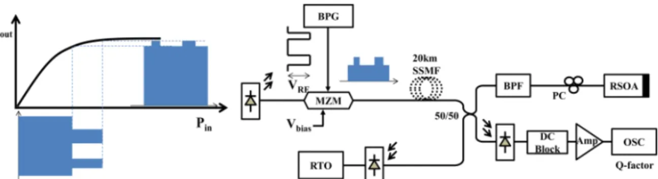
Figure 7: (Left) MI compression in saturated SOA. (Right) experimental setup to investigate effect of OOK-DL MI on received Q-factor and noise variance of reflected carrier.
It should be noted that the RSOA's working point can be defined not only by the optical mean power of the DL signal but also by its drive current. However, since it is located at the ONU where a centralized control is preferred, varying the MI of the OOK-DL signal at the CO becomes more practical.
While studying the suggested technique, we carry out the experiment shown in figure 7 (right), where back to back (B2B) operation omits the 20 km of SSMF between the MZM and the 50/50 coupler at the ONU. The downstream OOK signal is generated by modulating a continuous wave (CW) with an electrical NRZ pseudo-random binary sequence (PRBS) 231–1 signal output from a bit pattern generator at 1 Gb/s. The wavelength and Vπ of the MZM are respectively of 1550 nm and 5 V. A high-power tunable laser (Cobrite-DX1) is employed to generate the CW with a 15 dBm output power. The average optical power after the MZM reaches around 5 dBm. The signal spreads through the fiber before it is split by the 2×2 3 dB-splitter. One arm leads to the receiver containing a 10 GHz PIN photodiode, a dc block, an electrical amplifier, a 980 MHz RF low-pass filter, and a 20 GHz sampling scope (OSC) in order to measure the DL signal eye-diagram and Q-factor by built-in functions. The other arm goes through a 0.7 nm optical band-pass filter (BPF) and a polarization controller before reaching the RSOA (SOA-R-OEC-1550 from CIP), where the amplitude modulation is erased. The polarization controller is employed to maximize the input power to the RSOA because it is polarization selective (20 dB). In practice, to reduce complexity and cost, a polarization insensitive to RSOA should be favored. For all experiments, the drive current for the RSOA is kept at 50 mA.
Normally, the reflected light is modulated by the UL signal and transmitted back to the CO through the same transmission fiber. However, in order to examine the residual DL modulation, we use the other end of the 2×2 coupler to bridge the unmodulated carrier to a photo-receiver and therefore acquire both the ac and dc components of the resulting electrical signal by an 8 GSa/s real-time scope. The optical BPF also has its role
12
in rejecting the RSOA spontaneous emission (ASE) noise out of the return signal. We measure the standard noise deviation on the electrical trace by taking the histogram and using the built-in function on the RTO.
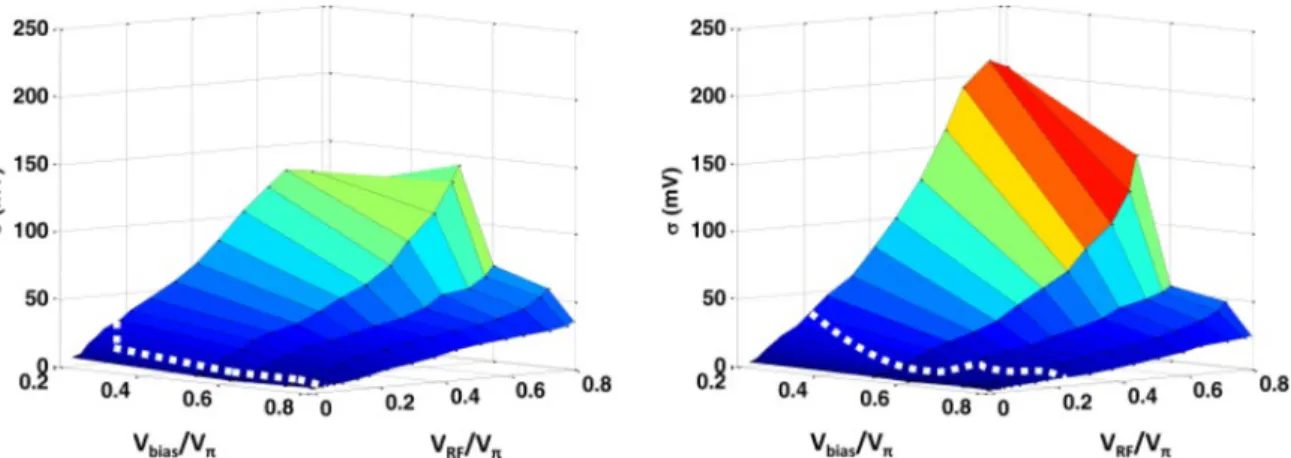
By varying the MZM Vbias and Vπ in the positive slope region of the transfer function from respectively 0.2 Vπ to 0.8 Vπ and 0.01 Vπ to 0.82 Vπ, we reveal the relationship of the standard noise deviation (σ) on the reflected carrier as the 3D-planes shown in figure 8 for B2B (left) and 20 km of SSMF (right). It should be noted that we normalize Vbias and VRF to Vπ in order to become independent from the modulator in use. In such conditions, the MI of the OOK-DL signal, which is defined as MI = VRF / (2Vbias), may vary from 0.4% to 100% in various scenarios where different dc levels of optical power are sent to the RSOA. Even though ER and mean power are quite commonly used to describe to characteristic of an OOK optical signal, we choose Vbias, VRF and MI as the tuning parameters because they are linearly related and suitable for intuitive demonstration of the ac and dc levels of the optical DL signal. The MZM also is chosen because of lab availability although electro-absorption modulated integrated lasers (EML) are recommended for current PON standard [32]. Generally, the control mechanism remains valid.
Figure 8: (Left) noise standard deviation on the reflected carrier as a function of Vbias and VRF driving the MZM: B2B, (right) after 20 km
of SSMF. Dotted lines are Q-factor = 6 boundary. Vbias and VRF are normalized to Vπ.
At any fixed value of Vbias, the noise standard deviation is negligible when a very small VRF increases with VRF quite linearly. It should be noticed that the slope is higher at lower Vbias : this can be explained by the fact that at lower Vbias, the optical DL level in the OOK-DL signal is lower, which makes the RSOA bias point moves further from the saturated regime and lowers the erasing efficiency.
When VRF is fixed and Vbias varies, the noise standard deviation increases as Vbias decreases. The slope of noise versus Vbias curves is higher at an higher VRF, increasing particularly fast at a VRF above 0.6 Vπ. The peak noise standard deviation of the transmission case is higher than that of the B2B case because the insertion loss of the fiber reduces the optical power into the RSOA, moving the working point toward the linear regime and limiting the erasing effect. At a fixed drive current, the RSOA saturation point is mainly defined by
the input signal dc level, which is in turn controlled by Vbias. Therefore, Vbias is expected to have an important impact on defining a proper operating point.
As shown quite clearly on figure 8 (right), there are cases where the noise standard deviation saturates, particularly when Vbias is low and VRF swing is high. This happens because the MZM is working in a nonlinear regime, therefore the increase in VRF does not transfer to an increase of the OOK-DL's ac swing.
In order to derive the operational region, we use the OOK-DL performance as the lower bound. It is well-known that the Q-factor for NRZ-OOK signal should be at least 6 in order to maintain BER at 10−9 (or error-free). It is possible to measure the Q-factor sweeping Vbias and VRF to obtain the boundary lines (white dotted line) along which Q-factor = 6 for B2B and 20 km transmission cases. For B2B, the boundary is on the lower edges of the 3-D-plane along VRF = 0.08 Vπ, while after 20 km of SSMF the limiting line rises and the workable region is narrowed towards higher Vbias and VRF.
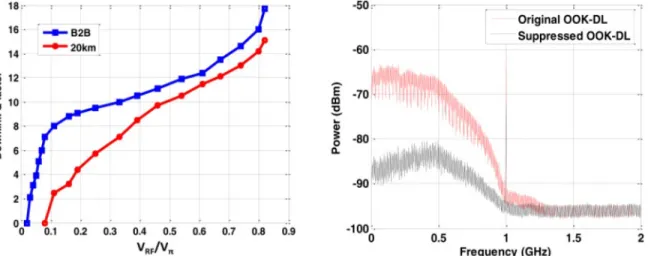
One can expect that when Vbias is set for MZM linear operation, VRF plays the main role in defining the modulation index and therefore in affecting Q-factor. Results in figure 9 (left) demonstrate the evolution of OOK-DL Q-factor when Vbias = 0.59 Vπ and VRF varies for B2B, and after 20 km of SSMF. In order to stay in the error-free region for OOK-DL, that is above 6, we restrain the VRF margin. In the B2B base, we can obtain VRF as low as 0.05 Vπ while VRF = 0.28 Vπ is needed for 20 km of SSMF transmission. As long as the fiber length increases, the lower bound defined by the OOK-DL Q-factor increases and shrinks the working region.
Figure 9: (Left) MI compression in saturated RSOA. (Right) electrical spectra of incoming OOK signal to the RSOA and its suppressed reflection.
Figure 9 (right) depicts the electrical spectra of the OOK signal coming to the RSOA (red) and the reflected carrier (black) for B2B case when their optical power are kept equal and the MZM is driven with Vbias and VRF are respectively 0.59 and 0.6 Vπ. A removal of more than 20 dB can be achieved, and it is more prominent at
14
lower frequency because of the high-pass filtering effect of RSOA, as it is depicted in [33]. Thus, we expect the UL signal to stay in-band with the DL signal, which is also inside the typical 1.25 GHz bandwidth of the RSOA.
In short, by properly setting Vbias and tuning VRF, we can maintain error-free performances of OOK-DL, and simultaneously minimizing the amplitude modulation noise on the reflected carrier. Another concern regards a certain fiber length or a power budget : we are wondering how can one can derive the proper control procedure to obtain the satisfactory performance given that the SNR required for analog Wi-Fi signal is quite high (>22 dB to support 64 QAM), as specified in [34].
1.5 Individual Effect of V
biasand V
RFon DL/UL Performance
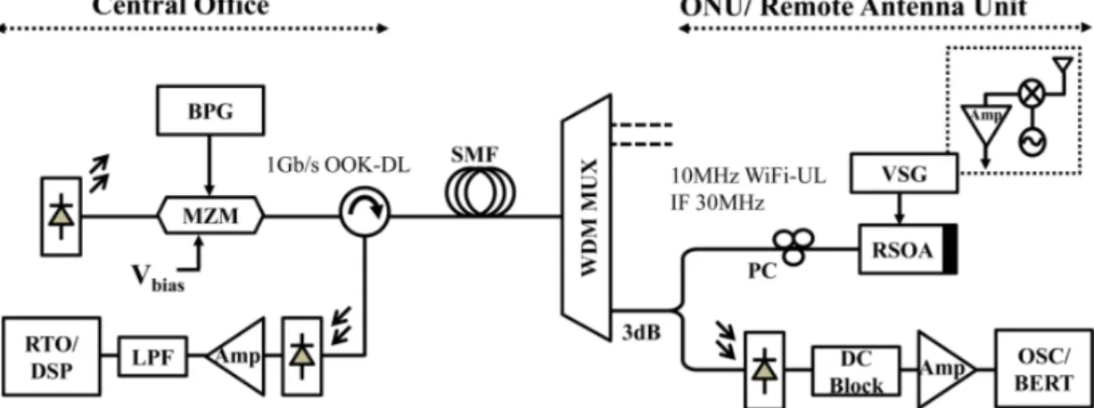
In this section, we separately adjust Vbias and VRF in driving the MZM to measure their individual effect on DL and UL performance. We thus carry out a full-duplex experiment, as it is depicted in figure 10. We introduce the 100 GHz spacing WDM-MUX as it is usually seen in WDM-PON system. The circulator is used at the CO as a UL/DL stream discriminator. Because of lab availability and the ease of DSP developing, it is the analog OFDM-UL signal that is chosen as Wi-Fi IEEE 802.11a standard. It is generated by MATLAB and downloaded into a programmable vector signal generator (VSG) using a 100 MSa/s digital-to-analog converter (DAC). No FEC is used throughout this process. The 802.11a frame structure contains OFDM symbols for the preamble and data payload stages. The former is used for frame synchronization as well as channel estimation. The latter uses all supported modulation modes, including QPSK, 16 QAM and 64 QAM, for upstream rate up to 54 Mb/s. The OFDM signal is mixed with 30 MHz intermediate frequency in order to simulate the down-conversion of a Wi-Fi signal traveling from a pass-band (around 2.4 or 5.5 GHz) to the RSOA bandwidth of 1.2 GHz. The electrical power rests at 12 dBm. The UL signal is processed offline and acquired by a 10-bit real-time scope working at 100 MSa/s. Offline signal processing steps are as follow : base-band down-conversion, re-sampling, frame-synchronization, frequency offset removal, preamble-based channel estimation, frequency domain equalization, demodulation and detection.
EVM values for QPSK, 16QAM and 64QAM of the demodulated OFDM-UL signal and the Q-factor of the OOK-DL signal are depicted in figure 11 (left). In this case, Vbias is fixed at 0.3 Vπ and VRF varies from 0.12 Vπ to 0.54 Vπ, resulting in a MI ranging from 20 to 90%. The OOK-DL optical power after the MZM rests around 5.5 dBm while the transmission loss to the RSOA at 11 dB, generating an input average power to the RSOA around –5.5 dBm. The Q-factor of the OOK-DL signal exceeds 9.3 and increases linearly with VRF. At VRF < 0.3 Vπ, the intrinsic background noise of the 10-bit RTO is higher than the residual DL modulation, forming the EVM floors for each modulation mode. As VRF increases over 0.3 Vπ, the EVM values for all modulations increase, just as the results shown in figure 8 were predicting it.
Figure 11: (Left) Q-factor of OOK-DL signal and EVM of OFDM-UL signal as a function of VRF. (Right) EVM of OFDM-UL signal as a
function of Vbias when OOK-DL Q-factor = 6.3 (solid), 12 (dotted).
We expect that given a large Q-factor margin, a wider operational region or better performance may be achieved with higher Vbias and smaller VRF driving the MZM. To investigate this hypothesis, we first set a small Vbias and then adjust VRF so that Q-factor of the OOK-DL signal sits around 6.3. By fixing VRF at that value and changing Vbias, we obtain the EVM curves for the UL signal with all modulation formats, as it is shown in figure 11 (right). All the EVM curves are flat, indicating that the modulation noise from DL signal rests below the system noise level. The Q-factor doesn't change with Vbias as long as the OOK-DL optical power doesn't saturate the photo-receiver at the ONU. By repeating the experiment with a new preset VRF to obtain a Q-factor of 12, the EVM curves will start at higher values if Vbias is small, and decrease considerably as Vbias reaches 0.6 Vπ. This corresponds to the operating point of the RSOA whether approaching the saturation region or growing deeper into it. The OOK-DL and the OFDM-UL performances can be balanced by setting proper values for Vbias and VRF. The lower boundary of Vbias may be derived to ensure that the FEC threshold (different for each modulation format) is respected. The pre-FEC threshold is calculated from the acceptable packet error rate (PER) of 10% when the packet length (PL) is 1000 bytes or 8000 bits [34]. Based on the relationship where PER = 1 – (1 – BER)PL, the tolerable post-FEC BER rests around 10−6. Using standardized interleaving and convolution code CC (171,133) rate 1/2 with Viterbi hard-decision error correction scheme, the equivalent pre-FEC BER is about 1.10−3. For other rates such as 2/3 and 3/4, Viterbi soft-decision scheme
16
should be employed to generate the same BER level. By adjusting Vbias in order to reach EVM floors, optimal performance for the UL signal can be obtained. When higher VRF is used to improve the OOK-DL signal, the EVM curve is higher at a low Vbias, resulting in a smaller region for Vbias and in the maintenance of a OFDM-UL signal below FEC threshold.
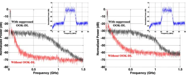
Figure 12 presents the captured spectra of the OFDM-UL signal for B2B on the left and after 20 km of SSMF on the right. The black curve follows the OOK-DL signal when it is turned ON and the red one, when it is turned OFF. As the OOK-DL signal is absent, the replica of the OFDM's spectrum (a consequence of the sampling effect) can be seen since the replica adds up to the noise shaped by the RSOA's high-pass filtering effect, resulting in a flat out-band noise floor. Comparing the OFDM spectra for B2B and 20 km of SSMF cases, the degradation is quite negligible.
Figure 12: (Red) spectra of OFDM-UL signal over the reflected carrier when OOK-DL is OFF, (black) ON and suppressed, (left) for B2B, and (right) after 20 km of SMMF. Overlapped figures are the zoomed-in views of OFDM-UL signal.
The optical power at the output of the MZM comprises the dc and ac components depending on Vbias and VRF settings. When the MZM works in the linear regime, Vbias controls the optical dc level, which in turn determines RSOA saturation level, whereas VRF trades-off the OOK-DL and UL performance. By knowing the operational region for these two parameters, one can develop a good technique to balance the quality of DL and UL signals. More importantly, as the aim of this system is to centralize power management and DSP, the proposed technique allows all balancing to be carried out at the CO where sophisticated monitoring and control are well developed.
1.6 Transmission Results and Discussion
In order to investigate achievable transmission distance, we measure the UL/DL performance over different lengths of SSMF ranging from 2 to 80 km. As the RSOA saturation condition changes with fiber length, the operation point for the MZM has to be readjusted to balance out UL and DL performances. For an OOK-DL
signal, we keep the received Q-factor = 6 as we are looking for the least possible interference or the best performance for the OFDM-UL signal.
Figure 13 (left) shows the evolution of the MI for the OOK-DL signal to ensure an invariant Q-factor of 6 as transmission length increases and the eye-diagram (inset) depicts each stage. Vbias is tuned between 0.5 V and 0.6 Vπ while VRF varies greatly in the aims of obtaining the required Q-factor. Thus, the MI can increase quite linearly with fiber length. Maintaining these conditions, we transmit the OFDM-UL and examine the UL reception at the CO. Figure 13 (middle) shows the measured EVM and the corresponding OFDM-UL signal's BER with various modulation levels as a function of fiber length. Examples of constellations that are produced when a received Wi-Fi signal experiencing different modulation modes at various fiber lengths are shown in figure 13 (right). UL performance degrades slowly at first, since the RSOA modulation erasure is still efficient, but gains a lot a speed upon reaching over 60 km of SSMF. To some extent, this phenomenon is caused by the larger MI required for DL signal, but mostly by the lower incoming power to the RSOA, desaturating it. Such a fast degradation is also caused by the decrease of UL power to the lowest acceptable level at the CO photo-receiver. Results for 64QAM when the fiber length exceeds 60 km are not shown here because the EVM value is no longer reliable. Pre-FEC BER values show that Wi-Fi signal can successfully be transmitted over very long distances whose limits depend on a chosen modulation mode. Applying the FEC threshold to the results, it can be noted that 64QAM is workable up to 40 km of SSMF. For 16QAM and QPSK, however, the reachable distances are respectively of 70 and 80 km.
Figure 13: (Left) MI of the OOK-DL to maintain error-free performance, (inset) OOK-DL eye-diagram; (middle) EVM/BER of WiFi OFDM-UL signal using different modulation modes. Example constellations for QPSK (60, 70 km), 16QAM (40, 60 km), 64QAM (20, 40 km).
The transmission distance of RoF systems is mainly limited by the delay restrictions between DL and UL signals imposed by current wireless standards employing a time division duplexing technique. The extension of reach can be enabled by adopting a dynamic MAC layer protocol [35] or by using frequency division duplexing (FDD). In our experiment, the Wi-Fi standard is operated in FDD mode for motives of convenience
18
even though it is quite infrequently used in commercial systems. The delay isn't an issue in newer standards such as LTE, where FDD is well-supported and a configurable DL/UL allocation is available.
Effect from Rayleigh back scattering isn't significantly encountered in all experiments. The UL signal power to the receiver (10 GHz PIN photodiode) is about –5 dBm when the fiber length is 20 km and the input power to the RSOA is −5.5 dBm. That is to say that the gain of the RSOA is equivalent to the fiber loss of about 11 dB. As fiber length increases, input power decreases and RSOA gain grows. The gain reaches either below or close to the total loss in all cases, resulting in a negligible effect from Rayleigh back scattering, as it has been studied in [36]. Excluding the connectors going to the photodiodes which are PC, everything is APC in order to limit back reflection. Moreover, the fact that the downstream signal is modulated to a certain broad bandwidth lessens the backscattering effect, usually quite severe for CW seeding light.
1.7 Conclusion
We just presented a technique which enables full-duplex transmission of OOK-DL and OFDM-UL signals in a RSOA-based WDM-PON system. By properly adjusting the driving condition in generating the OOK-DL signal, the modulation erasing in RSOA can be assisted to suppress the residual DL modulation effectively. As a result, the reflected optical carrier is clean enough to allow the transmission of analog OFDM-UL signal. We have investigated the effect of the controlling parameters on the performance of the DL and UL signals, generating an operational region as well as a proper tuning method that can be implemented at the CO to balance performances of both streams. Experimental results show that by applying this technique, bidirectional digital/analog transmission with satisfactory performance can be achieved with up to 80 km of SSMF. The results testify that analog RF signals can be transmitted under appropriate system designed and point the possibility of introducing analog signal into the digital PONs.
Chapter 2
Multi-service OFDM Uplink Transmission in
Full-Duplex FTTx Systems Using RSOA-based
WDM-PON Architecture
2.1 Résumé
Le projet comporte donc deux premiers coauteurs et, en raison de la répartition égalitaire des tâches, il y a eu une alternance des noms pour le premier auteur lors de la parution des articles. Pour la première fois et de manière expérimentale, nous démontrons la transmission de plusieurs signaux analogiques OFDM WiFi en amont avec un signal numérique OOK en aval sur un distance de 20 km utilisant une fibre monomode dans une architecture WDM-PON bidirectionnelle basée sur le RSOA.
2.2 Abstract
We are empirically demonstrating, for the very first time, the transmission of multi-service analog OFDM Wi-Fi uplink signal along with OOK downlink signal over 20 km of single mode fiber in a full-duplex RSOA-based WDM-PON fiber-to-the-x system.
2.3 Introduction
Recently, the merging of wireless computer/cellular and optical fiber communication systems is attracting a growing attention, as fiber-to-the-x (FTTx) broadband networks have been widely commercialized. When the fiber-wireless interface reaches the RF front-end (or the antenna), sophisticated and energy-consuming electronic subsystems can be relocated from the user end to the central office. This resources and power managing centralization can significantly reduce the system's cost and power consumption, thanks to well-developed controlling algorithms.
Wavelength division multiplexing passive optical network (WDM-PON) has been proven to be the key architecture for implementing FTTx systems [37] – [39]. More precisely, reflective semiconductor optical amplifier (RSOA) has been utilized to eliminate the need for a laser at the optical network unit (ONU), making the user terminal wavelength transparent and lowering the system cost. However, since single-fiber full-duplex RSOA-based systems suffer from the imperfect downlink modulation erasing of the RSOA, the performance is quite limited. In most reported studies, On-Off-Keying (OOK) modulation format is mainly employed for both downlink (DL) and uplink (UL) transmission. In previous works [40] and [30], we have demonstrated that by properly tuning the extinction ratio of the OOK-DL signal, an analog Wi-Fi OFDM-UL signal can be transmitted with error-free performance over 80 km of single mode fiber (SMF). In order to remain compatible with the
20
modern wireless system, which either handles various standards or services simultaneously, either employs a multiple-input multiple-output (MIMO) technique, one would expect the wireless-fiber interface to support multiple antennas.
In this paper, we wish to introduce a system for multiple receiving antennas and to demonstrate how the transmission of multi-service analog OFDM-UL signal in a single-fiber full-duplex system over 20 km of SMF works. Both OOK-DL and Wi-Fi OFDM-UL signals are successfully received with required performances, which is to say that bit error rates (BER) rest below 10−9 for OOK-DL signal and below the pre-forward error correction (pre-FEC) level of 10−3 for Wi-Fi OFDM-UL signal. Moreover, we measure the RSOA's bandwidth and test the spectral spacing tolerance to determine a number of supportable services and a possible managing method.
2.4 Working Principle and Experimental Setup
Figure 14: RF architecture supporting multiple receiving antennas (combined with figure 10).
Acting as a replacement for a modulator and a laser source, the RSOA at the ONU or the remote antenna unit (RAU) suppresses the modulation of the incoming DL signal, reflects and amplifies the light that needs to be used as a carrier for UL signal. The control current of the RSOA can then be managed directly by the UL signal to apply the modulation to the reflected carrier. Normally, the modulation erasure is imperfect, resulting in amplitude noise on the UL signal. This erasure depends on the ROSA's saturation level governed by the bias condition and the characteristics of DL signal. This phenomenon was studied in [41] and has taught us that by adjusting properly the extinction ratio of the OOK-DL signal, the latter's modulation can be suppressed effectively, therefore allowing the simultaneous transmission of UL signals, either through digital OOK [41] or analog Wi-Fi-OFDM modulation [40], [30].
We carry out the experiment depicted in figure 10 to demonstrate how the system we are recommending works. The OOK-DL signal is generated by modulating a tunable laser source with an electrical PRBS 231-1 non-return-to-zero OOK signal coming from a bit pattern generator (BPG). Data rate of 1 Gb/s is chosen so that the effect of the OOK-DL signal concentrates mainly in the 1.25 GHz bandwidth of the RSOA (SOA-ROEC-1550 from CIP). The DL signal goes through a circulator to then exit the CO, traveling through 20 km of
SSMF and a WDM-multiplexer (WDM-MUX) before reaching the ONU/RAU where it is split by a 3-dB coupler. One path goes to the receiver consisting of a photo-receiver, a DC-block and a sampling scope/bit-error-rate tester (OSC/BERT) where Q-factor and BER are measured. The other path goes through a polarization controller (PC), enters the RSOA which erases the DL modulation and then applies the UL signal as a new modulation to the reflected carrier. The UL signal propagates back on the same fiber link, follows the circulator's direction and reaches the CO's photo-receiver. The resulting electrical signal is acquired by a 10 GHz real-time scope with resolution of about 8 bits.
In order to simulate the signals received from multiple antennas, the UL signal is generated by programming a vector signal generator (VSG) with two IEEE 802.11a Wi-Fi services: each has 10 MHz bandwidth, compliant frame structure and supports all possible modulation formats (QPSK, 16QAM and 64QAM). Since the sampling rate of the digital-to-analog converter (DAC) in the VSG is limited to 100 MSa/s, the spectral between the two services is limited to 35 MHz We also propose a RF architecture for down mixing Wi-Fi services from 2.4 GHz or 5.5 GHz bands into the electrical bandwidth of the RSOA (0–1.25 GHz), as it is shown in figure 14 (right). Signals received from different antennas are mixed with a predefined intermediate-frequency (IF) distributed by a bank of programmable local oscillator. They are then combined together to create the UL modulating signal. In our setup, the spacing between two Wi-Fi services is kept at 5 MHz and the IF locations varies from 30 MHz to 1.25 GHz to study the performance of UL reception as a function of the spectral location.
The optical powers of the DL signal at the output of the Mach-Zehnder Modulator (MZM) and at the input of the RSOA are 4.5 and −5 dBm respectively. The power of the UL signal received at the CO's photo-receiver sets around −1.5 dBm. The reception of UL signal is carried out by offline digital signal processing (DSP) which consists in these steps. Firstly, we separate the two services by applying proper mixing and filtering. Secondly, we perform frame synchronization, channel estimation, equalization, and demodulating of the data payload. Finally, the error-vector magnitude (EVM) of the retrieved constellations and pre-FEC BER for all QPSK, 16QAM and 64QAM modulation schemes are calculated.
22
2.5 Results and Remarks
Figure 15: Spectrum of UL signal in the presence of OOK-DL signal (left); RSOA’s frequency response and measured SNR of UL signal (right).
We first examine the RSOA's erasure when the extinction ratio of the OOK-DL signal is varied by adjusting the controlling bias voltage and the amplitude swing of the electrical signal that drive the MZM. Following the study in [30], we optimize the erasing while the Q-factor of the received OOK-DL signal is maintained slightly above 6, which corresponds to a BER under 10−9. Figure 15 (left) shows the spectrum of the UL signal containing two Wi-Fi services obtained at the CO's receiver when the OOK-DL signal is turned on and off. The Wi-Fi services are located at 500 MHz Due to the impurity of the electrical carrier, even though harmonics are generated, they are rejected by filtering in DSP. When the OOK-DL signal is present, the achievable UL signal-to-noise ratio (SNR) sits around 30 dB, satisfying the requirement recommended by the IEEE 802.11 standard [26]. Figure 15 (right) reports the electrical frequency response of the RSOA (blue). One can expect that if a higher IF is chosen for a service, its power will suffer from the attenuation due to the roll-down of the RSOA's response, the SNR should be lower. However, it can be seen that the bell-shape spectrum of the OOK-DL signal also rolls down and has a null at 1 GHz, the "noise" power also reduces at higher frequencies. The fact that the electrical frequency response can be compensated by fueling it with more electrical power at a higher frequency while the noise power is significantly reduced, the SNR is expected to be higher at higher IF, especially around the null point of 1 GHz. It should be mentioned that the 1 Gb/s rate is chosen for OOK-DL to be comparable with the RSOA's bandwidth and to emphasize the effect of DL modulation residual on the UL signal. When a higher rate is chosen, i.e 10 Gb/s, the noise level gets flattened over the RSOA's bandwidth and its power lowers, resulting in a better UL performance.
Figure 16: EVM of received UL WiFi services (left); EVM tolerance with channel spacing (right).
Figure 16 (left) presents the EVM of the UL signal received at the CO. The performances for the two Wi-Fi services are identical, as they locate quite near to each other. The EVMs corresponding to pre-FEC BER threshold for each modulation format are depicted as acceptance margins. The overall results tell us that the Wi-Fi signals are successfully received with all modulation formats after transmission through 20 km of SMF and, as predicted, the best performance is obtained when the UL services are located around 1 GHz. Figure 16 (right) shows the EVM of the UL signals as a function of the spacing between two services where QPSK modulation is used. It can and should be noted that the performance degrades quickly as overlapping happens. However, the EVM is unreliable as we overlap both signals over 1 MHz since at least one useful subcarrier will therefore be interfering. The lower bound of 1 MHz corresponds to the overlapping of the guard bands of both services. From combining this result and the one obtained in figure 15, one can have an insight on the number of supportable services and their power distribution to obtain an optimal performance.
2.6 Conclusion
In this paper, we have been the first to empirically demonstrate the transmission of multi-service analog OFDM Wi-Fi uplink signal along with OOK downlink signal over 20 km of single mode fiber in a full-duplex RSOA-based WDM-PON FTTx system. The results have shown that multiple antenna wireless systems can be successfully interfaced with fiber communication systems in a full-duplex, flexible and cost-effective scheme. Required reception performances for both uplink and downlink are also achievable. Moreover, system robustness has been examined through a spectral spacing tolerance experiment. The recommended architecture shows a great potential as a prospect for an interesting FTTx solution, especially for fiber-to-the-antenna systems.
2.7 Acknowledgements
This work was supported by the Natural Science and Engineering Council of Canada (NSERC) under the Smart Applications on Virtual Infrastructure (SAVI) Research Network.
24
Conclusion
Dans ce mémoire, nous avons développé une technique de suppression de signal numérique par compression du gain optique dans les RSOA. Cette technique de suppression du signal a permis de démontrer expérimentalement, et pour la toute première fois, la possibilité d’établir des communications bidirectionnelles OFDM-UL et OOK-DL dans des applications WDM-PON basées sur les RSOA. Il a également été démontré expérimentalement qu’il est possible de transmettre plusieurs services OFDM-UL afin de supporter divers types de systèmes FTTx.
Dans le chapitre 1, la technique de suppression du signal numérique est démontrée et expliquée. Les conditions de saturation du RSOA pour la suppression du signal dépendent des paramètres de modulation du signal numérique OOK-DL arrivant au semiconducteur. Selon les paramètres de modulation Vbias et VRF qui déterminent l’indice de modulation, la qualité du signal supprimé est mesurée par la déviation standard du bruit résiduel en sortie du RSOA. En utilisant diverses combinaisons de valeurs pour Vbias et VRF au modulateur MZM, il est possible d’établir une relation entre les paramètres de modulation et la performance du signal OOK-DL en B2B et après une distance de propagation de 20 km. De cette manière, il est possible d’ajuster les paramètres de modulation du signal OOK-DL au CO afin d’avoir un BER < 10-9 et de maximiser la suppression du signal numérique en ayant la plus petite déviation standard du bruit résiduel afin d’optimiser les performances du signal OFDM-UL.
Il est également question de l’étude de l’impact des paramètres de modulation Vbias et VRF sur les signaux OFDM-UL. Le RSOA agit également en tant que modulateur RF. En faisant varier individuellement Vbias et VRF, nous sommes en mesure de déterminer la robustesse des signaux OFDM-UL QPSK, 16QAM et 64QAM et d’y obtenir une relation afin de caractériser la performance.
Avec la caractérisation de la performance des signaux OOK-DL et OFDM, il est donc possible d’ajuster les paramètres Vbias et VRF, afin d’obtenir des performances supérieures au seuil de correction (BER < 10-3) pour les signaux OFDM tout en gardant une bonne performance (BER < 10-9) au signal OOK-DL provenant du CO.
Une fois les critères de saturation du RSOA bien compris pour faire fonctionner les signaux OOK-DL et OFDM-UL simultanément en B2B, nous avons caractérisé leur performance en fonction de la distance de propagation. À chaque fois, nous avons ajusté l’indice de modulation MI pour diminuer la performance du signal OOK-DL à Q = 6 (10-9) afin d’optimiser les performances OFDM. En utilisant cette technique, il est possible d’établir des communications bidirectionnelles OOK-DL et OFDM-UL sur une distance de 40 km si le
![Tableau 1: Historique des prévisions de Cisco VNI [1].](https://thumb-eu.123doks.com/thumbv2/123doknet/3168112.90373/15.918.274.646.317.613/tableau-historique-prévisions-cisco-vni.webp)