3
rd
International Conference on
Ship Manoeuvring in Shallow and Confined Water:
with non-exclusive focus on
Ship Behaviour in Locks
3-5 June 2013 - Ghent, Belgium
rsion 20090422
Third International Conference on
Ship Manoeuvring in Shallow and Confined Water:
with non-exclusive focus on
Ship Behaviour in Locks
3 – 5 June 2013
Ghent, Belgium
Editors
Marc Vantorre (Ghent University)
Katrien Eloot (Flanders Hydraulics Research, Ghent University )
Guillaume Delefortrie (Flanders Hydraulics Research)
Evert Lataire (Ghent University)
Maxim Candries (Ghent University)
© 2013: The Royal Institution of Naval Architects / Ghent University / Flanders Hydraulics Research.
The Royal Institution of Naval Architects, Ghent University, Flanders Hydraulics Research are not responsible for the opinions expressed by the individual authors or speakers
THE ROYAL INSTITUTION OF NAVAL ARCHITECTS 10 Upper Belgrave Street
London SW1X 8BQ United Kingdom
Telephone: +44 (0)20 7235 4622 Fax: +44 (0)20 7259 5912
Cover photo: © Flanders Hydraulics Research ISBN No: 978-1-909024-17-5
rsion 20090422
Third International Conference on
Ship Manoeuvring in Shallow and Confined Water:
with non-exclusive focus on
Ship Behaviour in Locks
International Organizing and Paper Committee (OPC)
Reviewer
Affiliation
Prof. K. Benedict
University of Technology, Business and Design, Wismar, Germany
Dr. T. E. Berg
Marintek-Sintef, Norway
Dr. G. Delefortrie
Flanders Hydraulics Research, Belgium
Prof. T. De Mulder
Ghent University, Belgium
Dr. L. Daggett
Waterway Simulation Technology, USA
Dr. J. Duffy
Australian Maritime College Australia
Prof. K. Eloot
Flanders Hydraulics Research, Ghent University, Belgium
Dr. A. Gronarz
Development Centre for Ship Technology and Transport Systems,
Germany
Prof. K. Kijima
Nagasaki Institute of Applied Science, Japan
Prof. B. Pettersen
Norwegian University of Science and Technology, Norway
Prof. J. Pinkster
Pinkster Marine Hydrodynamics, The Netherlands
F. Quadvlieg
MARIN, The Netherlands
Prof. P. Rigo
ANAST, University of Liege, Belgium
Prof. F. Stern
IIHR - Hydroscience & Engineering, The University of Iowa, USA
Dr. C. Thorenz
Federal Waterways Engineering and Research Institute (BAW),
Germany
Prof. M. Vantorre
Ghent University, Belgium
O. Weiler
Deltares, The Netherlands
J. Wong
Panama Canal Authority, Panama
Review co-ordination
Dr. M. Candries
Ghent University, Belgium
Local Organizing Committee
Maxim Candries
Ghent University
Guillaume Delefortrie
Flanders Hydraulics Research
Katrien Eloot
Flanders Hydraulics Research, Ghent University
Sigrid Goethals
Flanders Hydraulics Research
Viki Kruyniers
Flanders Hydraulics Research
Evert Lataire
Ghent University
Frank Mostaert
Flanders Hydraulics Research
Patrik Peeters
Flanders Hydraulics Research
Marc Vantorre
Ghent University
Jeroen Verwilligen
Flanders Hydraulics Research
Ellen Vyncke
Ghent University
Preface
Scale enlargement in the shipping industry appears to be an ever-lasting trend. Particularly in container
transport, the limit is not yet in sight. When the successful Second International Conference on Ship
Behaviour in Shallow and Confined Water was being organised in Trondheim two years ago, the largest
container carrier afloat had a capacity of 14 500 TEU. The limit of 16 000 units has been reached since
then, and 18 000 TEU giants will be launched in the very near future. These new vessels will not only
distinguish themselves by their overall dimensions; their propulsion system and speed characteristics will
be essentially different compared to their predecessors’, driven by concerns about fuel prices and
emissions.
These evolutions are scrupulously watched by
harbour and waterways authorities, who experience
the continuous need to evaluate whether new and
larger types of ships will still be able to make use of
their infrastructure in the – even near – future. In
order to guarantee an acceptable safety level, they
continuously have to adapt their acceptance policy,
reconsider
operational
limits
and
nautical
procedures, have more sophisticated aids to
navigation developed and have tug fleets extended.
If these measures are assessed to be insufficient,
widening and deepening of port areas and their
access channels must be taken in consideration,
which generally implies decisions with important
financial and environmental consequences. In some
cases, adapting the dimensions of existing
infrastructure is no option at all. This is particularly
the case when the access to a terminal requires the
passage through a lock or a lock complex.
The construction of locks implies important investments with public and/or private funding. The final
decision on the characteristics of the lock and on the maximum dimensions of the ships which will be
allowed is irreversible and will determine the degree of economic success of the infrastructure for the next
decades. The last few years have seen a growing interest in lock design and construction, both for
maritime and inland traffic, in Europe, as well as in the Far East and, of course, in Panama. In many cases,
new locks are being planned, designed or built with the purpose of replacing existing lock systems or
increasing their capacity. As a consequence, a lock designer mostly needs to take account of many
constraints imposed by the present situation, the existing shipping traffic and environmental
considerations, so that the location of locks and the layout of their access channels are seldom optimized
from the ship handling point of view. The design of new locks therefore not only creates new challenges
with respect to the hydraulic and civil engineering aspects, but it must always be borne in mind that a new
infrastructure can only be successful if ships are able to approach, enter and leave the lock in a safe and
efficient way. The importance of a profound knowledge of the hydrodynamic effects to which ships are
subjected throughout the complete locking process has been recognised by PIANC, evidence of which is
given by the formation of InCom Working Group No. 155, “Ship behaviour in locks and lock
approaches”.
This international interest certainly justifies the selection of the topic “Ship Behaviour in Locks” as the
main focus for the Third International Conference on Ship Manoeuvring in Shallow and Confined Water.
Moreover, it is hard to find any environment where a more intense interaction occurs between a ship under
way and the navigation area. Shallow and confined water effects cannot be experienced more extremely
than during lockage manoeuvres.
It is perhaps not appropriate to speak of traditions when discussing a series of conferences that only started
four years ago, but the Knowledge Centre Manoeuvring in Shallow and Confined Water tries to keep in
mind a few basic principles. Along with the call for papers for each conference, benchmark model test
data obtained at the experimental facilities of Flanders Hydraulics Research have been made available for
the validation of simulation models and numerical calculation tools. For the present conference, a number
of tests with self-propelled models carried out to investigate the behaviour of vessels transiting the
Panama Canal Third Set of Locks has been chosen, as well as a selection of captive model tests conducted
in the towing tank for manoeuvres in shallow water in a scale model of the Pierre Vandamme Lock in
Zeebrugge. Several research groups have again made use of this opportunity and will present their
findings during this conference.
Secondly, all conferences so far have been organised with a focus on one particular topic without
excluding other subjects related to the behaviour of ships in shallow and confined waters and keeping in
mind that in daily practice most hydrodynamic effects do not occur separately. As a result, the conferences
offer a forum for recent developments in research on shallow water manoeuvring, bank effects, ship-ship
interaction, squat and other phenomena ships are subjected to in harbours and their approaches. A
continuous and ever increasing international interest in these specific aspects of ship hydrodynamics and
nautical practice can be observed in international organisations. For example, the present ITTC
Manoeuvring Committee explicitly mentions the study of possible criteria for manoeuvring at low speed
and in shallow waters. The best-selling PIANC report appears to be “Approach Channels – A Guideline
for Design”, of which a long-expected updated version entitled “Horizontal and Vertical Dimensions of
Fairways” will be issued shortly. A similar effort is being carried out for inland waterways by PIANC
Working Group InCom 141, “Design Guidelines for Inland Waterways”.
Finally, the organisers wish to create a meeting place for both researchers and nautical experts. Problems
concerning ship behaviour in shallow and confined water cannot be reduced to merely academic
questions. Scientific research can only contribute effectively to practical solutions if researchers have a
clear idea about the daily practice, while providing pilots and masters with a more thorough insight into
the physical phenomena dominating a ship’s reaction in confined water may contribute to safer
manoeuvres.
The first conference, with focus on bank effects, was organised in 2009 in Antwerp, the home base of
Flanders Hydraulics Research. NTNU and Marintek organised the second edition in Trondheim in 2011
within the framework of a successful project studying ship-to-ship operations. The third conference will
offer a busy technical program: 35 presentations, two keynote speakers and a visit to locks in operation
and under construction in the Port of Antwerp. For several reasons, the Knowledge Centre has selected
Ghent as the venue for the third Conference. Not only because this city is the seat of the academic partner
of the Knowledge Centre, but also because of the strong link between Ghent and the main topic of the
conference. Safe and smooth lock operations are of the utmost importance for the Port of Ghent, both for
the maritime and the inland shipping traffic. For both transport modes, important infrastructure works
including extension or replacement of lock complexes are presently being studied, planned and executed.
Lastly, the venue – Ghent University’s Convention Centre “’t Pand”, with its unique location in the
historic heart of Ghent – allows the organisers to offer the delegates a well-balanced combination of a
busy technical program with a selection of social activities offering the opportunity to catch a glimpse of
the highlights of Ghent’s cultural heritage and establish personal and professional relationships.
On behalf of the Royal Institution of Naval Architects, Flanders Hydraulics Research and Ghent
University, we wish all participants a pleasant and fruitful conference.
Welcome to Ghent!
SHIP MANOEUVRING BEHAVIOUR IN CROSSING CURRENT
K Hasegawa, K G Oh and Y A Ahmed, Osaka University, Japan P Rigo, University of Liege, Belgium
SUMMARY
Ship behaviour in a current is one of the classical problems in ship manoeuvrability. However, it is not yet fully investigated. The study is motivated by an assessment study on the ship navigation near-by a river lock where a relatively strong current exists, and simulations are done to demonstrate how the ship behaves in a current. As a result, relatively large drift angles are obtained, where the ship is around perpendicular to the current and the current speed is relatively large. In normal ship speed, the drift angle is almost less than 20° where a normal mathematical model based on lift theory can be applied, but even if the ship speed is not low, in presence of current, a mathematical model for low speed should be considered. The phenomena should more frequently occur, if the current is not uniform, and the way to calculate in such case is discussed.
NOMENCLATURE R A Rudder area (m2) B Breadth of ship (m) R b Rudder breadth (m) B
C Block coefficient of ship (-)
P
D Propeller diameter (m)
d Draft of ship (m)
N
F Rudder normal force (N)
Na
F Apparent rudder normal force (N)
R
h Rudder height (m)
zz
I Yaw moment of inertia (kg m2)
m Ship mass (kg)
x
m Added mass in surge (kg)
y
m Added mass in sway (kg)
N Yaw moment (N m) , ,
H P R
N N N Yaw moment components of hull,
propeller and rudder (N m)
n Propeller revolutions per minute (rpm)
P Propeller pitch (m)
r Angular velocity in yaw(deg/s)
r Angular acceleration in yaw(deg/s2)
'
r Non-dimensional angular velocity (-)
t Thrust deduction factor (-)
c
U Current speed (m/s)
d
U Drifting speed due to current (m/s)
R
U Rudder inflow velocity (m/s)
Ra
U Apparent rudder inflow velocity (m/s)
'
U Non-dimensional ship speed (-)
u Speed in surge (m/s)
a
u Apparent speed in surge (m/s)
Ra
u Apparent speed of rudder in surge(m/s)
c
u Current speed in surge (m/s)
a
u Apparent acceleration in surge (m/s2)
v Speed in sway (m/s)
a
v Apparent speed in sway (m/s)
Ra
v Apparent speed of rudder in sway (m/s)
c
v Current speed in sway (m/s)
a
v Apparent acceleration in sway (m/s2)
X Surge force (N) , ,
H P R
X X X Surge force components of hull,
propeller and rudder (N)
G x Centre of gravity in x-axis direction (m) Y Sway force (N) , , H P R
Y Y Y Sway force components of hull, propeller and rudder (N)
Z Number of propeller blades (-)
R
Rudder inflow angle (deg)Ra
Apparent rudder inflow angle (deg)
Drift angle of ship (deg)
Rudder angle (deg)Λ Aspect ratio of rudder height to chord length (-)
Ship heading (deg)c
Current direction (deg)d
Drifting angle due to current (deg)1. INTRODUCTION
In a narrow water channel/river where there is fast current/stream exists, ship cannot be operated in high speed and the ship motion has relatively large drift angle. To assess the safety of ship operation in such circumstances, it is important to simulate the ship motion in current/stream accurately. If there are some obstacles in waterway such as islands, shallow bottom/water splash, a lock or flood gate etc., the ship behaviour is quite complicated because of the current/stream near-by the obstacles. This paper aims to predict ship behaviour in such case. There are already some researches [1-6] mostly done in 1970s in Japan, because in Japan there are many strong current waterways mostly in an inland sea called "Setonaikai", due to the fact that there are strong ocean current as well as strong ocean tidal, there exists large difference of sea surface at the orifices between
In these researches, they [2,3,4] treat mathematical model using apparent velocity due to the current. Even though they did not quote, this concept is probably first proposed by Crane [7]. He has also proposed to use cross flow model which can be applied for the calculation of ship motion in a non-uniform current, although he did not apply it for simulation.
Ogawa [4,5,6] used the shear flow model instead of the cross flow model. He [4] researched about the shear flow model numerically, and for validation of the model, he [5] conducted experiment. Then, the model is applied to actual problem [6]. Honda, et al. [1] studied the research based on real ship observation/measurement, and heading angle distribution between simulation and observation/measurement is compared. Iwai et al. [3] studied about the influence of current around the bridge pier for safe course-keeping of ship, and they [3] showed the dangerous zone is wide and the ship manoeuvring is rather effective to the reverse current. However, as their [1-6] research aim is to estimate a ship's motion in such a place, they did simulation based on the measured current distribution, and they did not draw general conclusion on the influence of the current.
Kashiwagi [8] used cross flow model for simulation of ship motion in a non-uniform current, following Crane's [7] concept.
Yang and Fang [9] have also worked for this subject, and proposed new distribution forms of hydrodynamic force and moment on the basis of wing theory. Their model is expressed following Ogawa [6] and Kashiwagi's [8] expression way, and Crane's [7] apparent speed concept is used.
In this paper, the basic behaviour of ship motion in a current will be discussed using apparent speed concept proposed by Crane [7]. For the main purpose of this paper, ship behaviour near-by a lock should be calculated using cross flow model, but at the same time, the importance of low speed manoeuvring model is pointed out. Actual simulation of the ship motion near-by a lock will be done based on the measured/estimated current distribution with mathematical model for low speed, although in this paper, it is not yet done.
2. SHIP MANOEUVRING MOTION IN CURRENT
2.1 MATHEMATICAL MODEL UNDER UNIFORM CURRENT
In this chapter basic mathematical model treating uniform current will be summarized.
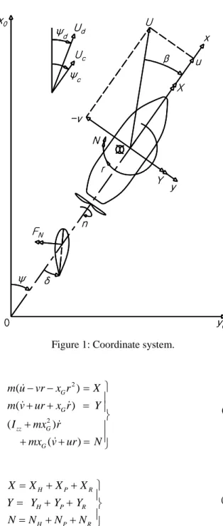
Coordinate system and definition of symbols and their positive directions are shown in Figure 1. There are several expressions to express external forces and moment (X, Y and N) in eq. (1), but here they are
FN n x0 y0 r -v β N U x y Y u X δ 0 Ψc Uc Ψ Ud Ψd FN n x0 y0 r -v β N U x y Y u X δ 0 Ψc Uc Ψ Ud Ψd
Figure 1: Coordinate system.
2 2 ( ) ( ) ( ) ( ) G G zz G G m u vr x r X m v ur x r Y I mx r mx v ur N ( 1 ) H P R H P R H P R X X X X Y Y Y Y N N N N ( 2 )
In the expressions of each external force and moment, apparent speeds ua and va are used as shown in eq.
(3), instead of u and v respectively, when a current exists.
cos(
)
sin(
)
a c c a c cu
u U
v
v U
( 3 )
where Uc is current speed,
cand
are the currentdirections and ship heading angle respectively. It is described, as shown in e.g. eq. (4). The detail expression is based on MMG model [10,11], but it is not unique and not necessary to be the same expression.
2 2 4 2 2 2 2 (1 ) (1 ) sin (1 ) cos ( ) cos a x a y vv a vr a rr vvvv a R N a y a x v a r vv a a rr vv r a v rr a H N z v a r vv a a rr vv r a v rr a R H H N X u m v r m X v X v r X r X v t T R t F Y v m u r m Y v Y r Y v v Y r r Y v r Y v r a F N rJ N v N r N v v N r r N v r N v r x a x F
( 4 )where t is thrust deduction factor, T is thrust, and R is resistance of a ship. In the term of rudder force, tR is
effective wake coefficient, δ is rudder angle. FN is
rudder normal force as shown in eq. (5).
2 2 2 1
sin
2
tan
N R R R R R R R R RF
A f U
U
u
v
v
u
( 5 )
where
A
R andf
are rudder area and the gradient of the lift coefficient of rudder respectively, UR is inflowvelocity of rudder, and
R is inflow angle.u
R andv
Rare surge and sway speed at rudder. For more detail of
R
u
andv
R, refer [10,11]. In order to treat current, the concept of apparent speed which is shown in eq. (6), must be used for the UR and
R.cos(
)
sin(
)
Ra R c c Ra R c cu
u
U
v
v
U
( 6 )
As a result, eq. (5) is transformed as eq. (7), the subscript
N, a and R of FNa, URa and αRa means normal, apparent
and rudder respectively.
2 2 2 1
sin
2
tan
Na R Ra Ra Ra Ra Ra Ra Ra RaF
A f U
U
u
v
v
u
( 7 )
2.2 MATHEMATICAL MODEL IN NON-UNIFORM CURRENT
2.2 (a) Hydrodynamic Force and Momnet Acting on a Hull
In non-uniform current situation, lateral hydrodynamic force cannot be calculated properly using MMG model. Because of this problem, Ogawa [4,5,6] proposed the shear flow model as shown in eqs. (8,9,10). The lateral force Y and yaw moment H N acting on a ship due to a H current can be expressed as shown in eq. (8), if it is expressed in the distribution component.
/ 2 / 2 / 2 / 2 ( ) ( ) L H H L L H L H Y y d N n d
( 8 )where the lateral force and moment distribution alongside longitudinal direction
y
H( )
andn
H( )
can be expressed as eq. (9). ( ) ( , ) ( ) ( ) ( , ) ( ) H a H a y h v r f n h v r f
( 9 )where h v( , )a r is the lateral force distribution for given
a
v
andr
, andf
( )
is defined as eq. (10)./ 2 / 2 ( ) 1 L L f
d
(10) On the other hand, Kashiwagi [8] proposed to use cross flow model originally proposed by Crane [7] for the lateral force and moment, which can be applied for a non-uniform current directly. The non-linear terms in Y and N expressions in eq. (4) are replaced with the cross flow models which are expressed as YNL(va, r) and NNL(va,r) as shown in eq. (11), where v used in normal, cross
flow model are replaced with va.
1/ 2 1/ 2 1/ 2 1/ 2 ( ) ( ( ) ) ( ) ( ( ) ) NL D a a NL D a a Y C v r v r d N C v r v r d
(11)where CD is drag coefficient of hull at drift angle is 90°.
Yang and Fang [9] proposed a similar expression of
( )
H
y
based on wing theory.2.2 (b) Hydrodynamic Force Acting on a Rudder
In non-uniform current situation, Uc and
care differentaccording to the position in space fixed coordinate system. Moreover, for hull and rudder, different two concepts of apparent speed are required. The apparent speed at hull have to be calculated using eq. (3), and the apparent speed for rudder have to be calculated using eq.
3. SIMULATION OF SHIP MANOEUVRING MOTION IN CURRENT
For the estimation of ship manoeuvring motion in a current, simulation studies are carried out. As the subject ship, Esso Osaka model is used, and the principal particulars are listed in Table 1. The simulation is conducted at ship speed is 0.495 m/s with various current speed.
Table 1: Principal particulars of subject model.
Hull Length, L (m) 3.000 Breadth, B (m) 0.489 Depth, d (m) 0.201 Block Coefficient, CB 0.831 Propeller Propeller Diameter, Dp (m) 0.084 Pitch, P (m) 0.060 No. of Blades, Z 5 Rudder Rudder Breadth, bR (m) 0.080 Rudder Height, hR (m) 0.128 Rudder Area, AR (m2) 0.010 Aspect Ratio, Λ 1.54 3.1 SIMULATION IN VARIOUS CURRENT CONDITIONS
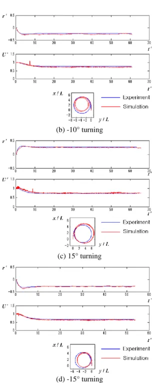
Before conducting the simulation in current, in order to validate the mathematical model and its coefficients, turning simulation is conducted in several rudder angle conditions without current, and results are compared with the free running experiment data as shown in Figure 2. They match well respectively, so the model and its coefficients are validated.
(a) 10° turning
(b) -10° turning
(c) 15° turning
(d) -15° turning
Figure 2: The comparison of several turning motions between experiment and simulation.
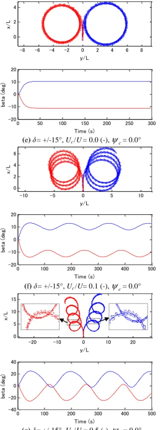
The simulation is conducted for rudder angle is 15º in various current conditions and the results are shown in Figure 3. Figure 3(e) is the result without a current for the comparison with others (f-h). The upper graph is the ship's trajectory and the lower graph is the time history of drift angle (β) respectively. The upper graph of Figure 3(e) is same with the trajectories of Figure 2(c-d), but drift angle is added for the comparison between others (f-h). It is found that the drift angle is saturated to around +/-10º in steady turning. In case of Figure 3(f-h), turning circle radius is almost same but drifting down stream side with slightly starboard side for starboard turning and vice versa for port turning. Looking inside the time history of
the drift angle and enlarged part of the trajectories, it is also found that the drift angle fluctuates around the saturated value of the case (e) and the degree of the fluctuation is proportional to the current speed ratio to the ship speed. Due to this fluctuation, the ship has larger drift angle in down stream side (12 O'clock direction, if the turning trajectory is regarded as a clock) of a turning circle and vice versa in the upper stream side (6 O'clock direction) of a turning circle. On the other
-8 -6 -4 -2 0 2 4 6 8 0 2 4 y/L x/ L 0 50 100 150 200 250 300 -20 -10 0 10 20 Time (s) be ta ( de g) (e) δ= +/-15°, Uc /U= 0.0 (-), c
= 0.0° -10 -5 0 5 10 0 2 4 6 y/L x/ L 0 100 200 300 400 500 -20 -10 0 10 20 Time (s) be ta ( de g) (f) δ= +/-15°, Uc /U= 0.1 (-),
c= 0.0° -20 -10 0 10 20 0 5 10 15 y/L x/ L 0 100 200 300 400 500 -40 -20 0 20 40 Time (s) be ta ( de g) (g) δ = +/-15°, Uc /U = 0.5 (-),
c= 0.0° -40 -30 -20 -10 0 10 20 30 40 0 10 20 30 y/L x/ L 0 100 200 300 400 500 -60 -40 -20 0 20 40 Time (s) be ta ( de g) (h) δ= +/-15°, Uc /U = 1.0 (-), c
= 0.0°Figure 3: Simulation results in various current speed ratio conditions with current direction is 0°.
hand around 3 O'clock direction and 9 O'clock direction the drift angle is almost same with the value of the case (e). This asymmetry of the drift angle makes the
trajectory to drift (which is not the same terminology of
the ship drift angle and to be defined as trajectory drift [12]) starboard side for starboard turning and port side for port turning. Figure 4 shows the relation of the
trajectory drift angle in term of |
d|-
c, where
d is the trajectory drift angle and the current speed ratio to the ship speed. Figure 5 shows the relation of thetrajectory drift speed of the trajectory defined as Ud in
ratio to Uc and the current speed ratio to the ship speed.
0 5 10 15 20 0 0.2 0.4 0.6 0.8 1 1.2
Current speed ratio (UC /U )
(d e g ) Starboard turning Port turning dc
Figure 4: The relation between current speed ratio and drifting angle. 0 0.05 0.1 0.15 0.2 0.25 0 0.2 0.4 0.6 0.8 1 1.2
Current speed ratio (UC /U ) Starboard turning Port turning
/
dc
UU
Figure 5: The relation between current speed ratio and drifting speed ratio.
(1) The ship trajectory drifts to the down stream side, when a ship makes turning in a uniform current, but slightly starboard side for starboard turning and vice versa for port turning. This tendency is also obtained by You and Rhee [13].
(2) The trajectory drift angle has not clear tendency, and different between starboard and port turnings with the current speed ratio to the ship speed, but roughly speaking, the difference of this value is not so large and around 10-17º.
(3) Contrary, the trajectory drift speed is almost proportional to the current speed ratio to the ship speed and not much different between starboard and port turnings.
(4) In a single turning circle, even if the trajectory drifts, the ship drift angle is different with the ship position in the circle. Around 12 O'clock, if the circle will be regarded as a clock, there exists larger drift angle and the value is almost proportional to the current speed ratio to the ship speed, while around 6 O'clock, the value is smaller than that of no current condition. If the current speed ratio to the ship speed exceeds 0.5, the maximum drift angle exceeds 20º. It suggests that in such large drift angle range due to current/stream, a normal mathematical model such as eq. (4) cannot be applied, but a low speed manoeuvring model should be used, because the normal mathematical model expresses the hydrodynamic forces and moment acting on a ship only within the drift angle range of about +/-20º.
For the detail of the low speed manoeuvring model Oh and Hasegawa [14, 15] summarized several models and compared their applicability. Calculating ship motions in non-uniform current and applying a low speed manoeuvring model, more preside ship behaviour in sophisticated current/steam condition can be obtained.
4. CONCLUSIONS
In the present study, ship manoeuvring in a current is reviewed and simulated. In various current speed ratios to ship speed, the influence of current is studied, and the obtained results are summarized below.
1) In most cases, if the current speed ratio to ship speed is not high, conventional mathematical model can express ship motion in current well.
2) Even if the ship speed is not so low, there are some current conditions where hydrodynamic forces/moment have to be treated considering low speed model.
3) The influence of low speed mathematical model and
analysis under tsunami or some ship accident analysis in a river.
5) The influence of ship drifting in a current at turning motion is shown respective to current ship speed ratio.
5. REFERENCES
1. HONDA, K., A. YAMAGUCHI, S. MATSUKI, M. HIROTA, T. INOUE, K. KATO, K. INOUE, ‘On the Controllability of Ships Affected by the Turbulent Flow in the Kurushima Middle Channel’ (in Japanese), The Journal of Japan Institute of Navigation, Vol. 45, pp. 55-64, 1971.
2. KARASUNO K., ‘Simulator Studies of Ship Maneuvering Motions in Non-uniform Tidal stream’ (in Japanese), Bulletin of the Faculty of Fisheries
Hokkaido University, Vol. 34, pp. 231-249, 1983.
3. IWAI, A., K. SHOJI, ‘On the Effect of Current around the Pier upon the Course-Keeping of Ship’ (in Japanese), The Journal of Japan Institute of
Navigation, Vol. 61, pp.163-172, 1979.
4. OGAWA, A., ‘Calculation on the Steered Motion of a Ship under the Action of External Forces (Part 1) Course keeping and Turning of a Ship in Uniform wind and flow’, Selected Paper from the Journal of
the Society of Naval Architects of Japan, Vol. 7, pp.
124-137, 1971.
5. OGAWA, A., ‘Calculations on the Steered Motion of a Ship under the Action of External
Forces
(Part 2) Analysis of Motion Derivatives by a New Mathematical Model’, Selected Paper from theJournal of the Society of Naval Architects of Japan,
Vol. 12, pp. 33-45, 1974.
6. OGAWA, A., ‘On the Capsizing of a Ship in Strong Tidal Current Area -An Analysis of Ship Motions in a Shear Flow on the basis of Calculation’ (in Japanese), The Journal of Japan Institute of
Navigation, Vol. 57, pp. 119-128, 1977.
7. CRANE, Jr., C.L., ‘Studies of Ship Maneuvering “Response to Propeller and Rudder Actions”’,
Supplemental paper in Proc. of Ship Control Systems Symposium, Vol. 1, pp.IV-B-44-88, 1966.
8. KASHIWAGI, M., ‘A New Method for Calculating the Maneuvering Motion of a Ship in Non-uniform Current and Its Application in Naruto Kaikyou’ (in Japanese), The Journal of Japan Institute of
Navigation, Vol. 75, pp. 55-67, 1986.
9. YANG, Y., X. FANG, ‘Simulation Model of Ship Manoeuvring Motion in Uneven Current and its Application’ (in Chinese), Shipbuilding of China, No. 1 (Serial No. 140), pp. unknown, 1998 referred by ITTC Manoeuvrability Committee Report, Proc.
of 22nd ITTC, pp.47, 1999.
10. (The original articles including [11] are written in Japanese, but summarized by several persons, e.g.) YOSHIMURA, Y., ‘Mathematical Model for Manoeuvring Ship Motion (MMG Model)’, Proc. of
Workshop on Mathematical Models for Operations Involving Ship-Ship Interaction, 2005.
11. OGAWA, A., HASEGAWA, K., YOSHIMURA, A., ‘Experimental Verification and Improvement of the Mathematical Model of Manoeuvring Motion of Ships’ (in Japanese), Bulletin of the Societey of
Naval Architects of Japan, no. 616, pp. 565-576,
1980.
12. INTERNATIONAL MARITIME ORGANIZATION, ‘Explanatory Notes to the Standards for Ship Manoeuvrability’, MSC/Circ. 1053 Annex, pp. 14-21, 16 December 2002.
13. YOU Young-Jun, Key-Pyo RHEE, ‘Wind and Current influence acting on the course change of ship’ (in Korean), Proc. of the Korean Institute of
Navigation and port research conference, pp. 23-25,
2011.
14. OH, K.-G., K. HASEGAWA, ‘Ship Manoeuvring Hydrodynamic Forces and Moment in Low Speed’,
Proc. of Advanced Maritime Engineering Conference 2012 (AMEC 2012), Paper
No.SNOM-09, pp. 1-8, 2012.
15. OH, K.-G., K. HASEGAWA, ‘Low Speed Ship Manoeuvrability - Mathematical Model and its Simulation’, Proc. of the ASME 2013 32nd
International Conference on Ocean, Offshore and Arctic Engineering (OMAE 2013), to be published,
2013.
6. AUTHORS BIOGRAPHY
Kazuhiko Hasegawa is a professor of Graduate School
of Engineering, Osaka University, Japan. He had a position of vice president of Japan Society of Naval Architects and Ocean Engineers (JASNAOE) and deputy editor of Journal of Marine Science and Technology (JMST) and Journal of JASNAOE etc. He is a member of International Federation of Automatic Control (IFAC) Marine-TC etc. His speciality is ship manoeuvrability, controllability, marine traffic, marine transportation and ship accident analysis.
Kyoung-Gun Oh is a PhD candidate at Graduate School
of Engineering, Osaka University, Japan. His previous
experience includes ship manoeuvrability of single-propeller twin-rudder system in low speed as well as optimal control of single-propeller twin-rudder ships.
Yaseen Adnan Ahmed is a PhD candidate at Graduate
School of Engineering, Osaka University, Japan. His current research is automatic ship berthing using artificial neural network.
Philippe Rigo is a professor, head of Naval Architecture
and Transport Systems (ANAST) of University of Liege, Belgium and coordinator of a Master Erasmus Mundus program - Advanced Ship Design (EMSHIP). His speciality is ship structure, ultimate strength, ship optimisation, inland navigation and waterborne infrastructures.