HAL Id: hal-01339892
https://hal.archives-ouvertes.fr/hal-01339892
Submitted on 30 Jun 2016
HAL is a multi-disciplinary open access
archive for the deposit and dissemination of
sci-entific research documents, whether they are
pub-lished or not. The documents may come from
teaching and research institutions in France or
abroad, or from public or private research centers.
L’archive ouverte pluridisciplinaire HAL, est
destinée au dépôt et à la diffusion de documents
scientifiques de niveau recherche, publiés ou non,
émanant des établissements d’enseignement et de
recherche français ou étrangers, des laboratoires
publics ou privés.
Application of the Variational Theory of Complex Rays
to the determination of shock induced vibration of a
reinforced concrete structure
Christophe Rouzaud, Fabrice Gatuingt, Guillaume Hervé, Olivier Dorival,
Nadim Moussallam
To cite this version:
Christophe Rouzaud, Fabrice Gatuingt, Guillaume Hervé, Olivier Dorival, Nadim Moussallam.
Appli-cation of the Variational Theory of Complex Rays to the determination of shock induced vibration of
a reinforced concrete structure. 14th International Conference on Structures Under Shock and Impact
(SUSI 2016), May 2016, Crete, Greece. �hal-01339892�
Application of the Variational Theory of Complex Rays
to the determination of shock induced vibration of a
reinforced concrete structure
C. Rouzaud
1, F. Gatuingt
2, G. Hervé
1, O. Dorival
3,4, N. Moussallam
51
Université Paris-Est, RENON (IRC-ESTP, IFSTTAR), IRC-ESTP, 28 avenue du
Président Wilson, 94234 Cachan, France
2
LMT (ENS Cachan, CNRS, Université Paris Saclay), 61, avenue du Président Wilson,
94235 Cachan, France
3
Icam, site de Toulouse, 75 avenue de Grande-Bretagne, 31076 Toulouse Cedex 3,
France
4
Université de Toulouse, Institut Clément Ader (ICA), INSA, UPS, Mines Albi, ISAE,
135 avenue de Rangueil, 31077 Toulouse Cedex, France
5
AREVA, 10 rue Juliette Récamier 69006 Lyon, France
Abstract
Security and safety are crucial aspects in the design of nuclear engineering structures. Civil engineering design and the qualification of materials to dynamic loads must consider the acceler-ations which they undergo. These acceleracceler-ations could integrate not only seismic activity but also shaking movements consecutive to aircraft impacts with higher cut-off frequency.
Current methodologies for handling such a shock in the calculation stage are based on transient analyzes using classical finite element methods associated with explicit numerical schemes or projection on modal basis. In both cases, to represent in a meaningful way a mediumfrequency content, a fine mesh is required which is hardly compatible with the size of models of the civil engineering structures. In order to extend the current industrial methodologies and to allow a better representation of the behavior of the structure in the medium-frequency range, an approach coupling a temporal and non-linear analysis of the impact area with a frequency approach for the treatment of the resulting shaking with the Variational Theory of Complex Rays (VTCR) has been developed [1]. The aim is to use the computational efficiency of the implemented strategy and to include the medium frequency range to calculate the nuclear structures response to an aircraft impact.
1 Introduction
For nearly three years in the framework of pre-normative research in nuclear construction (RENON), the constructability research institute (IRC) focused some of its efforts on improving the charac-terization of floor response spectra in the case of aircraft impacts.
The study of airplane crash in the design and verification of nuclear engineering structures has two important and distinct aspects: (i) the resistance of the structure subjected to an impact, loading, and (ii) the qualification of inner equipments to the vibrations induced. The calculation of the resistance of the structure and its design do not generally raise problem with current meth-ods, however, the calculation of induced vibrations, although few harmful to inner equipments, requires special attention especially with the lack of efficiency of current approaches. Indeed the calculation of floor response spectra (FRS) in this case generally exhibits a set of high magni-tude accelerations within a frequency range that is generally much higher than the one observed when calculating the FRS due to an earthquake. The cutoff frequency for this type of loading would be referred to as the medium frequency range [2]. The determination of the response by classical finite element method associated with explicit time schemes requires significant calcu-lation time. A new multiscale computational strategy, using the Variational Theory of Complex Rays [3], was developed [1] for the analysis of the vibration of structures in the low and medium frequency regime.
The purpose of this study is to use new ways for calculating the induced vibrations and com-pare the FRS between different types of aircraft impact. The paper is structured as follows: Sec-tion 1 presents the descripSec-tion of the strategy used; SecSec-tion 2 describes an example case; SecSec-tion 3 illustrates the determination of the non-linear area through a non-linear FE calculation; Sec-tion 4 explains the VTCR method and shows its applicaSec-tion on the industrial structure; finally, conclusions and perspectives are drawn in Section 5.
2 Description of the studied case
2.1 Description of the structure
Let us consider a concrete structure. The mechanical properties of concrete are extracted from the rules of Eurocode 2 [4]:
• maximum compression strength of the concrete, fck= 60 MPa,
• Young’s modulus, E = 34 GPa, • Poisson’s ratio, ν = 0.2,
• mass density, ρ = 2500 kg/m3,
• hysteretic damping coefficient, ξ = 0.07.
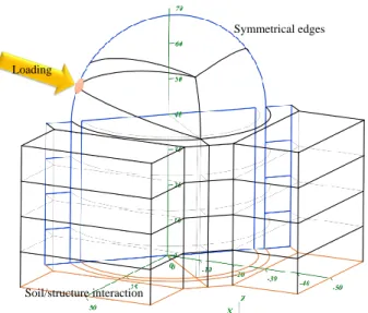
In this study, a hysteretic damping is used. The structure (see Figure 1) is entirely constituted of 1 m thick shells. It comprises four peripheral square buildings and one central cylindrical building with a dome shaped roof. The entire building is reinforced by reinforcement HA40@20
cmin both directions, or 0.63 %/m. The soil is modeled as an infinite half-space using standard
approximations (see [5]). It is defined in the system through stiffness and damping in translation and rotation. In this example, the soil is described by:
• shear modulus, G = 7, 76.108N/m2,
• Poisson’s ratio, ν = 0.33,
Symmetrical edges
Loading
Soil/structure interaction
Figure 1: Geometry of the numerical example.
The soil/structure interaction is defined at the raft in all three directions in translation with
stiff-ness equal to 5, 808.1010 N/m and damping of 8, 348.108N.s/m and in rotation with stiffness
equal to 1, 104.1018N.m/rad and 1, 587.1010N.m.s/rad in damping.
2.2 Impact signal: Riera approach
The structure is subjected to a normal impact applied at the surface S1of the dome. This impact
produces localized damages on this part of the structure. The radius of the non-linearity area will be calculated in a first step by a standard explicit FEM calculation and from this calculation, the temporal attenuated signal in displacement across the damaged area will be applied on the rest
of the structure [6]. We consider the load at S1as a force for various aircraft impacts calculated
by Riera’s analytical approach [7]. Three types of aircraft belonging to each category of aviation (light, military and commercial) will be studied.
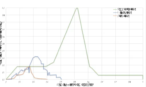
Figure 2 compares the mass distributions for the various types of aircraft. In the approach for calculating the impact force defined by [7], the parameter that plays a major role is the impact velocity of the aircraft. In order to qualify the nuclear structures to aircraft impact, we have cho-sen to set this value between landing and cruising velocity. Figure 3 shows the different impact forces obtained. One can observe that commercial and military are higher than light aviation. It is therefore unnecessary to consider this one to qualify our structures in an aircraft crash.
3 Definition and results across the non-linear damaged area
For the determination of the damaged non-linear area, we use the FEM code LS-Dyna [8] coupled with Lagrangian Finite Element and an explicit time integration. Given the initial geometry, we decided to focus the study on the dome structure and the boundary conditions are defined as displacements constraints.
Commercial aircraft Military aircraft Light aircraft
Normalized distance from front of plane Normalized distance from front of plane
aircraft mass distribution ormalized N 1.0 0.9 0.8 0.7 0.6 0.5 0.4 0.0 0.1 0.2 0.3 0 0.1 0.2 0.3 0.4 0.5 0.6 0.7 0.8 0.9 1
Figure 2: Comparison of mass distributions for the different types of aircraft.
0 1 Commercial aircraft Military aircraft Light aircraft Normalized time
Normalized impact force
0 0.1 0.2 0.3 0.4 0.5 0.6 0.7 0.8 0.9 1 0.1 0.2 0.3 0.4 0.5 0.6 0.9 0.7 0.8
Figure 3: Impact forces for the three different aircrafts.
behavior law Mat_Concrete_EC2 implementated in LS-Dyna and presented in [6] was used. Figure 4 shows the part of the structure studied in the treatment of the non-linear area. The loads considered correspond to those calculated by the Riera method, commercial and military aviation
presented in figure 3. These equivalent forces are applied on a surface of S1corresponding to the
𝑆1 28 m Symmetrical edges Constraints in displacement Loading
Figure 4: The structure geometry studied for the treatment of the non-linear zone.
-45 -40 -35 -30 -25 -20 -15 -10 -5 0 5 10 0 500 1 000 1 500 2 000 2 500 3 000 3 500 4 000 4 500 5 000 Commercial aircraft Military aircraft Time (ms) Displacement ( mm)
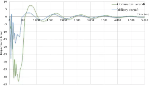
Figure 5: Displacement across the damaged area for both aviations.
The dome mesh is defined to be able to represent up to a frequency of 100 Hz, according to the technical rule of 10 elements per wavelength [9]. Thus, the mesh size is equal to 40 cm.
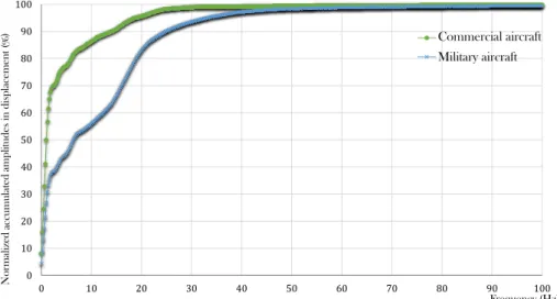
This non-linear calculation provides the radius of the damaged area, 10 m for commercial aircraft and 5 m for military aircraft, and the displacements across this area (see Figure5). Figure 6 shows the accumulated displacements across the non-linear area for the two cases studied in frequency. In conclusion regarding the treatment of the non-linear area, we can say that an aircraft crash induces localized damage around the impact area. We can also note that military aviation has a widerer frequency content than commercial aviation. Indeed, the accumulated displacements shows that the commercial load reaches 95 % of the amount of displacement at a frequency of 20 Hz and 99,7 % at 100 Hz. In comparison, the military aircraft reaches 95 % at 33
Hzand 99,5 % at 100 Hz. Once the damaged area determined, one can calculate the vibrations
0 10 20 30 40 50 60 70 80 90 100 0 10 20 30 40 50 60 70 80 90 100 Commercial aircraft Military aircraft Frequency (Hz) Normalize d amplitudes in displacement ( % ) accumulated
Figure 6: Accumulated displacements in frequency across the damaged area for both aviations.
4 Applying the signal to the remaining undamaged part of the structure
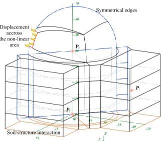
Determining the parameters controlling the non-linear area that is located around the impact surface allows to study the vibrations induced in the rest of the structure. To this aim one can use a frequency approach through the coupled FFT/VTCR/IFFT method described in [1]. The structure response is obtained by a simulation with the VTCR. This calculation requires a transformation from time to frequency domain that is achieved by FFT (Fast Fourier Transform). After solving the problem in the frequency domain, a time recomposition is performed by IFFT (Inverse Fast Fourier Transform). The displacement applied across the non-linear area is defined in Figure 5. To study the VTCR response and its efficiency versus a classical time approach, we defined
3 points of interest (P1, P2 and P3) on the structure where we reconstitute the displacements
and study the accelerations response spectra. These points are illustrated in Figure 7. Close to five hundred vibrating rays per substructure are sufficient to properly represent the frequency response. Table 1 shows the obtained solution for four sample frequencies.
Symmetrical edges Soil/structure interaction Displacement accross the non-linear area
Figure 7: Geometry of the linear part of the studied structure and location of points of interest.
Max numbers of DOFs / substructures: 100 interior waves 75 edge waves / edge, 50 pressure waves and 50 shear waves
Total = 25,000 waves 10 Hz Resulting displacement (mm ) 10 25 50 100 0,1 -0,1 -0,05 0,05 0 -0,025 0,025 0 -0,05 0,05 0 0 0,002 -0,002 -0,001 -0,001 -0,001 0,001 -5e-4 5e-4 25 Hz 10 25 50 100 0,1 -0,1 -0,05 0,05 0 -0,025 0,025 0 -0,05 0,05 0 0 0,002 -0,002 -0,001 -0,001 -0,001 0,001 -5e-4 5e-4
Max numbers of DOFs / substructures: 100 interior waves 75 edge waves / edge, 50 pressure waves and 50 shear waves
Total = 25,000 waves 50 Hz Resulting displacement (mm ) 10 25 50 100 0,1 -0,1 -0,05 0,05 0 -0,025 0,025 0 -0,05 0,05 0 0 0,002 -0,002 -0,001 -0,001 -0,001 0,001 -5e-4 5e-4 100 Hz 0 0 2,5e-4 -2,5e-4 -1e-4 1e-4 1e-4 -1e-4 -5e-5 5e-5
Table 1: VTCR frequency solutions for the studied case.
Following the VTCR calculations, one can recover amplitude and phase as a response at each point of the structure and for each frequency, and thus reconstruct the time response by inverse fast Fourier transform (IFFT). In the following paragraph we describe the results obtained at the
point P3, however [10] summarizes all the results obtained on the three points of interest. For
the selected point P3, the frequency amplitudes of the displacements and the time displacements
following the loading axis are described in Figures 8 and 9.
To validate the results obtained with the approach frequency, one can compare them to a clas-sical time finite element method. In this comparison, a refined mesh with a mesh size equal to 0.4
mand composed of 5.56 ∗ 106degrees of freedom is defined. If we refer to the engineering rule
of 10 elements per wavelength, this mesh can be used to represent a frequency range limited to 100 Hz. From these results, one can observe the good adequacy between the two approaches for the two categories of aviation. Figure 10 shows the mean normalized error for all post-treatment points on the resultant displacement between the two approaches. One can note that the am-plitudes of displacement in the case of a commercial aircraft are partially higher than those of a military aircraft, and in particular along the loading axis. This observation is tempered by the fact
that for P2and P3the frequency amplitudes for the out-of-plane displacement along the vertical
axis of a commercial aircraft beyond 10 Hz are lower than the other aircraft category.
Neverthe-less this displacement amplitudes remain below 1 ∗ 10−2mm. The normalized error confirms our
observation about good adequacy of results between the two approaches, particularly between 10 and 90 Hz. Two major error areas can be noticed: the very low frequency (0 - 5 Hz) and the last 10 percent of the frequency range studied (90 - 100 Hz). Two different reasons can explain these errors. For the very low frequency range, the VTCR presents some difficulties to represent too
Frequency (Hz) 1.E+0 0 1 10 100 1.E-1 1.E-2 1.E-3 1.E-4 1.E-5 1.E-6 (mm) amplitudes Displacement
Commercial aircraft - Time approach Commercial aircraft - Frequency approach Military aircraft - Time approach Military aircraft - Frequency approach
Figure 8: Amplitudes of the frequency content for the two aircrafts at point P3along the loading
axis. -9 -8 -7 -6 -5 -4 -3 -2 -1 0 1 2 3 4 0 500 1 000 1 500 2 000 2 500 3 000 3 500 4 000 4 500 5 000 Time (ms) D isplacem en t (m m)
Commercial aircraft - Time approach Commercial aircraft - Frequency approach Military aircraft - Time approach Military aircraft - Frequency approach
Figure 9: Temporal displacements at point P3along the loading axis.
large wavelengths solutions when approaching the static response. Errors on the highest part of the frequency range can be explained by the finite element representation which generates errors due to the number of elements per wavelength. Indeed in this frequency range, one reaches the limits of the chosen finite element discretization.
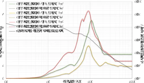
Figures 11 and 12 present the acceleration response spectra for the 3 points of interest, and the pseudo displacement response spectra. The damping considered for these spectra is 7 %. Along the loading axis, one can note that the very low frequency content (≤ 10 Hz), like commercial aircraft, is transmitted to the entire structure. On the other hand spectral accelerations involving
0 10 20 30 40 50 60 70 80 90 100 Commercial aircraft Military aircraft Frequency (Hz) Normalized error on the resultant displacement 0.4 0.3 0.2 0.1 0.0 1.0 0.9 0.8 0.7 0.6 0.5
Figure 10: Mean normalized error of average for all post-treatment points (P1, P2and P3) on the
resultant displacement between the temporal and frequency approaches.
1,E-6 1,E-5 1,E-4 1,E-3 1,E-2 1,E-1 1,E+0 0 1 2 3 4 5 6 0,1 1,0 10,0 100,0 Sp ectral ps eudo disp la cement (m) Frequency (Hz) S p ec tr al acceleration ( m /s² )
Commercial aircraft - Time approach - P1 Commercial aircraft - Frequency approach - P1 Commercial aircraft - Time approach - P2 Commercial aircraft - Frequency approach - P2 Commercial aircraft - Time approach - P3 Commercial aircraft - Frequency approach - P3 Pseudo envelop displacement response spectra
Figure 11: Acceleration response spectra for the three points of interest along the loading axis in the case of commercial aircraft.
medium frequencies (between 10 and 100 Hz) are partially filtered to internal structures. These remarks are suggested by pseudo spectral displacements that fall below 1 mm from 10 Hz.
The spectral responses alonng the vertical axis z lead to spectral accelerations which partially filtered the low frequencies and transmitted the medium frequencies. In this direction, the pseudo spectral displacement falls below 1 mm from 25 - 30 Hz.
0 1 2 3 4 5 6 Sp ectral ps eudo disp la cement (m) 1.E-6 1.E-5 1.E-4 1.E-3 1.E+0 1.E-1 1.E-2 0.1 1.0 Frequency (Hz) 10.0 100.0 S p ec tr al acceleration ( m /s² )
Military aircraft - Time approach - P1 Military aircraft - Frequency approach - P1 Military aircraft - Time approach - P2 Military aircraft - Frequency approach - P2 Military aircraft - Time approach - P3 Military aircraft - Frequency approach - P3 Pseudo envelop displacement response spectra
Figure 12: Acceleration response spectra for the three points of interest along the loading axis in the case of military aircraft.
5 Conclusions about the implementation of the strategy for an industrial
case
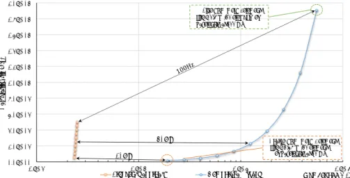
We can conclude from these results two important points. First, we note that the frequency ap-proach allows us to find, with fewer degrees of freedom, similar results to those obtained in the case of a sufficiently refined calculation by finite elements. Figure 13 shows the difference in CPU computing time for this problem between the two types of resolution. In this figure, the orange plot indicates various points representing the time required to calculate the solution by increments of 10 Hz. The blue curve gives the calculation time for different mesh densities. This density must be sufficient (10 elements per wavelength) to properly represent the solution. The frequency correspondence is achieved between the two approaches. One can conclude from this comparison that if the number of degrees of freedom remains lower for frequency VTCR ap-proach, the resolution of the complex and poorly conditioned system limits its effectiveness at low frequencies (up to 50 Hz here) compared to a finite element approach at least as long as. However if the number of wavelengths to be treated in the structure increases significantly, the FEM requires a more and more refined mesh what directly leads to a high computation time that can quickly reach prohibitive costs. The frequency approach is an effective methodology on the mid frequency range.
One can also conclude about the differences of induced vibration by the two types of air-crafts considered. One note that a commercial aircraft provides low frequency displacements and higher accelerations than a military aircraft that has a higher content at medium frequencies. Nevertheless beyond 30 Hz, the induced displacements fall below 1 mm and are less harmful for equipments.
50Hz 10Hz
Frequency approach Temporal approach Number of DOFs
Coarse FEM mesh - element
C alculation time (s) 2.0E+05 0.0E+00 2.0E+04 4.0E+04 6.0E+04 8.0E+04 1.0E+05 1.2E+05 1.4E+05 1.6E+05 1.8E+05
1.E+4 1.E+5 1.E+6 1.E+7
Fine FEM mesh - element size = 0.4 m (10 element per wavelength at 100 Hz
size = 1.25 m (10 element per wavelength at 10 Hz
Figure 13: Calculation time comparison for frequency and time approaches.
References
[1] Rouzaud, C., Gatuingt, F., Dorival, D., Hervé, G. & Kovalevsky, L., A new way for the sim-ulation of the impact on reinforced concrete structures. Engineering Computations, 32(8), pp. 2343–2382, 2015.
[2] Hervé, G., Rouzaud, C., Barré, F. & Secourgeon, E., Optimizing the analysis of airplane crash induced spectra by means of generic airplane methodology. Proceedings of the 22nd SMiRT, San Francisco, USA, 2013.
[3] Ladevèze, P., Arnaud, L., Rouch, P. & Blanzé, C., The variational theory of complex rays for the calculation of medium-frequency vibrations. Engineering Computations, 18, pp. 193–214, 2001.
[4] EC2, Eurocode 2 - Calcul des structures en béton. NF EN 1992-1-1, 2005.
[5] Tsai, N., Niehoff, D., Swatta, M. & Hadjian, A., The use of frequency-independent soil-structure interaction parameters. Nuclear engineering and design, 31(2), pp. 168–183, 1975.
[6] Rouzaud, C., Gatuingt, F., Hervé, G., Moussallam, N. & Dorival, D., Influence of the air-craft crash induced local nonlinearities on the overall dynamic response of a rc structure through a parametric study. Nuclear Engineering and Design, 298, pp. 168–182, 2016. [7] Riera, J.D., A critical reappraisal of nuclear power plant safety against accidental aircraft
impact. Nuclear Engineering and Design, 57(1), pp. 193–206, 1980. [8] Ls-Dyna. http://www.lstc.com/, 1976.
[9] Babuška, I., Ihlenburg, F., Paik, E.T. & Sauter, S.A., A generalized finite element method for solving the helmholtz equation in two dimensions with minimal pollution. Computer Methods in Applied Mechanics and Engineering, 128(3), pp. 325–359, 1995.
[10] Rouzaud, C., Ébranlement de structures en béton armé soumises à un phénomène transi-toire, 2015.