HAL Id: hal-01424947
https://hal.archives-ouvertes.fr/hal-01424947
Submitted on 3 Jan 2017
HAL is a multi-disciplinary open access
archive for the deposit and dissemination of
sci-entific research documents, whether they are
pub-lished or not. The documents may come from
teaching and research institutions in France or
abroad, or from public or private research centers.
L’archive ouverte pluridisciplinaire HAL, est
destinée au dépôt et à la diffusion de documents
scientifiques de niveau recherche, publiés ou non,
émanant des établissements d’enseignement et de
recherche français ou étrangers, des laboratoires
publics ou privés.
Compression technique for retrodirective reflectors using
transformation optics
Hassan Haddad, Renaud Loison, Raphaël Gillard, Akil Jrad, Ali Harmouch
To cite this version:
Hassan Haddad, Renaud Loison, Raphaël Gillard, Akil Jrad, Ali Harmouch. Compression technique
for retrodirective reflectors using transformation optics. MECAP2016, Sep 2016, Beirut, Lebanon.
pp.1 - 4, �10.1109/MECAP.2016.7790081�. �hal-01424947�
Compression Technique for Retrodirective
Reflectors Using Transformation Optics
Hassan Haddad
1,2*, Renaud Loison
1, Raphael Gillard
11IETR
INSA-Rennes Rennes, France
*Email Address: [email protected]
Akil Jrad
2, Ali Harmouch
2 2LaSTRe, EDSTLebanese University Tripoli, Lebanon
Abstract—In this paper, the design of compressed retrodirective reflectors via transformation optics is addressed. The proposed method enables a compressed reflector to perform as a classical retrodirective corner reflector while having a much lower profile. Using a simple linear coordinate transformation, the lower profile can be achieved with a TO domain in the reflector consisting of anisotropic homogeneous media. The proposed design is validated at f0=8GHz by full wave
electromagnetic simulations. Furthermore, using the Effective Medium Theory approach, the practical feasibility of the involved medium distribution is discussed and verified. The results of the investigations could be of interest in different radar, communication and identification applications.
Keywords—Retrodirective structure; transformation optics; effective medium theory; coordinate transformation; double layered system.
I. INTRODUCTION
The geometry of wave propagation is not as linear as popularly thought before. It is well known that free space provides a flat geometry for waves to propagate in a straight line and at a constant speed. But, Transformation Optics was first proposed in [1, 2] to formulate different methodologies and procedures in order to be able to manipulate light or any given electromagnetic wave.
Using coordinate transformation, which is applied to the constitutive parameters, electromagnetic waves in one coordinate system can be described as if propagating in a different coordinate system. The geometric interpretation of Maxwell’s equations utilized in the transformation optics approach provides a powerful and intuitive design tool for the manipulation of electromagnetic fields on all length scales as mentioned in [4].
The key new ingredient in the electromagnetic design methodology is the realization that under a coordinate transformation, the field lines of all conserved quantities are merely rearranged. In fact, they behave as though they were fixed to the coordinate system so that as we distort the coordinates, the field lines are dragged along. This rule applies to the electric displacement, the magnetic induction and the Poynting vector. The latter is of course the precise formulation of the rays associated with a propagating electromagnetic field. Hence, a coordinate transformation specifies the new values of the constitutive parameters and at the same time tells how the fields are rearranged [3]. These manipulations could be realized using specially designed devices that need to be put in front of an incident wave, for instance, in order for the intended variations in the EM waves to take effect. The first attempted device is an invisibility cloak [1, 2]. And from this first scheme came along many different methodologies for controlling EM waves in other ways and for a wide range of applications.
Using these ideas, numerous devices have been designed, such as a cylindrical magnifying lens [4], flat focusing lens [5], carpet cloaks [6], reflectors [7], wave collimators, shifters and splitters [8], etc.
Limitations always occur, especially in TO devices, where proposed designs could be accomplished theoretically and simulated but can be very complex to fabricate, even necessitate exotic material parameters or even constitutive parameters that cannot be obtained in practice.
One particular device of interest is the retrodirective reflector. It is a device that can reflect EM waves in the anti-parallel direction of the incident wave. Such a device is useful mainly for radar cross section, communication, satellite and identification applications. A classical retrodirective reflector can be designed using a corner reflector structure that consists of two metallic conducting sheets with an angle of 90° in between.
However, for most applications mentioned above, the classical reflector is quite cumbersome to be integrated. So, lower profile features are needed for this device. Many researches have already applied successfully different TO methodologies to design planar low-profile EM reflectors including the retrodirective reflector in [7, 9, 10 and 11]. However, most of the attempts lead to inhomogeneous anisotropic materials covering the conducting sheets of the reflector. These configurations, while they are attractive and close in performance to the classical reflector in theory and simulation, are either very complex or even unattainable with current construction technologies.
The latest research [7] in the field of reflectors was able to simplify the material distribution in the TO domain to a certain extent and obtain a planar profile but with degraded retrodirectivity performance and bulky dimensions of dielectrics instead of the metallic sheets.
The ultimate goal of this paper is to present a compression technique for the dimensions of the reflector without compromising its retrodirectivity performance.
It is divided into 4 parts. In the first part, the problem is clearly presented along with the methodology based on Transformation Optics and the theoretical design of the compression technique applied on a classical reflector along with different simulations. Next, in the second part, the practicality of the design along with different simplification and approximation procedures is discussed. In the third part, the effective medium theory (EMT) approach is discussed as a potential implementation for the following technique used for this type of reflectors. Last, in the fourth part, concluding remarks are presented discussing the effects of the compression technique along with the impact of tagging the EMT approach to the implementation of such an application.
II. METHODOLOGY &THEORETICAL DESIGN
Consider a retrodirective corner reflector design shown in figure1 below.
Figure1. The original 2D space of a corner reflector with its designated transformation.
For simplicity, it is restricted to a two dimensional (2D) case. The corner reflector has two perfect conducting (PEC) planes AB and BC perpendicular to each other. The arrows in figure 1 represent the normally incident and reflected beams of the reflector. Transformation optics methodology can be employed in order to transform such a corner reflector to a lower profile filled with a specific material. The coordinate transformation chosen in this scenario is schematically shown by the small arrows in figure 1 from lines AB and BC to lines AB′ and B′C. Only the y-coordinate has been transformed in a
linear way as shown in equations (1-3) below: x′= x
y′=b
ay
z′= z
Where 𝑎 and 𝑏 represent the dimensions of the final reflector. Under this coordinate transformation, the virtual free space (x, y, z) is transformed into a compressed area (highlighted area in fig. 1) in the physical space (x’, y’, z’). Based on the TO procedure [3], one could calculate the relative permittivity and permeability tensors of the material filling using the following equations [ε′] =[A].[A]
T
│A│ . [ε] and [μ
′] =[A].[A]T
│A│ . [μ] where [A]
here is the Jacobian matrix of the coordinate transformation used in [1, 2, 3].The y-coordinate transformation of the region yields to the following eq. (4) below:
[ε′] = [μ′] = [ a b 0 0 0 ba 0 0 0 ab] (4)
As seen from eq. (4), the advantage of choosing such linear coordinate transformations is that the resulting anisotropic material is homogeneous.
To demonstrate the proposed transformation on a classical retrodirective reflector, full wave EM simulations were conducted using the Finite Element Method through COMSOL Multiphysics simulator. Two compressed reflectors are considered with a=2b=15λ0 and a=4b=15λ0, where λ0 is the
free space wavelength of the 8GHz incident wave. The electric field norms are compared in figure 2 below.The black arrows represent the direction of propagation of the TM polarized EM-fields. A Gaussian beam is used for normal incidence in all simulations with a beamwidth 𝑤 = 4λ0. As seen from fig.2, the retrodirectivity performance of the classical reflector is conserved for any compression factor when using theoretical TO domains with accordingly material distribution.
Figure2. Electric Field Norms at normal incidence for (a) Classical Reflector, (b) Compressed Reflector using TO for a=2b, (c) for a=4b.
III. PRACTICALITY OF THE DESIGN
A. 1st Simplification Procedure:
As a way to simplify the obtained material tensors, which in order reduces the complexity of the design, one can choose a specific material suitable for only one incident wave polarization. For example, for transverse magnetic (TM) incident waves (with the magnetic field along the z coordinate) only the εx, εy and μz components of the material
properties are relevant to the wave. So then less material components are needed to be spread within the same region.
B. 2nd Simplification Procedure:
As described in [12], the parameters using the Material Interpretation could be simplified (in this case) such that the product of the following components εxμz and εyμz is unchanged which ultimately leads to a simpler material distribution.
So then the relative permittivity and permeability tensors could be written as follows in equation (5) below:
[ε′] = [ a2 b2 0 0 0 1 0 0 0 εz ] , [μ′] = [μ0𝑥 μ0 0 𝑦 0 0 0 1 ] (5)
In eq. (5) above, εz, μ𝑥 and μ𝑦 could be arbitrary value because of the 2D-space restriction and the material simplifications conducted above. It is important to add here that this parameter distribution can be approximated using birefringent materials. However, the reduction to non-magnetic parameters (especially here μ𝑧= 1) comes at the
expense of introducing impedance mismatching at the boundary of the reflector which yields to reflection losses as shown in figure 3 below.
Figure3. E-field Norms with Reduced μ′ of the TO domainfor (a) a=2b
(𝜀𝑥= 4, 𝜀𝑦= 1) and (b) a=4b (𝜀𝑥= 16, 𝜀𝑦= 1).
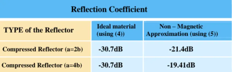
It is clearly shown, from table 1, that reducing the material parameters (specifically the permeability) using the material interpretation introduces additional reflection. Furthermore, these losses increase while increasing the level of compression of the retrodirective reflector as shown between the different compression scenarios of a=2b and a=4b.
Table1.Comparison of Reflection Losses values for different Retrodirective Reflectors.
Reflection Coefficient
TYPE of the Reflector Ideal material (using (4)) Approximation (using (5)) Non – Magnetic Compressed Reflector (a=2b) -30.7dB -21.4dB
Compressed Reflector (a=4b) -30.7dB -19.41dB
IV. PRACTICAL IMPLEMENTATION OF THE DESIGN
A. Double-layered System Implementation
From here onwards, such a design should be considered to be physically implemented. So, a flexible way to realize the birefringent dielectrics is the method called Effective Medium Theory (EMT) [13, 14]. The EMT methodology suggests synthesizing the birefringent dielectric with a multilayered medium constituted from 2 alternating isotropic dielectrics. In this representation, the layers are orthogonal to the y-axis, and the effective permittivity of the two layers is determined by the following set of equations [14]:
{ε′z= ε′x= ε1+αε2 1+α ε′y=(1+α)εαε 1ε2 1+ε2 (6)
Where ε1 and ε2 represent the relative permittivity of the dielectric 1 and dielectric 2, respectively and α =d1
d2 is the
thickness ratio of the two layers. A schematic of the dielectric implementation of the design is shown in figure 4 below.
Figure4. Representation of the dielectric layers distribution using EMT.
Careful considerations should take place in choosing the different values of the dielectric layers shown in figure 4 above. Using (6), the values of 𝜀1 𝑎𝑛𝑑 𝜀2 can be obtained in
function of their thickness ratio 𝛼 and for different dimensions of the designed retrodirective reflector (a and b). For instance, for 𝛼 = 1 which means the two layers have the same thickness and for dimensions of 𝑎 = 2𝑏, it leads to 𝜀1= 7.464 and 𝜀2=
0.5359.
In order to choose the most convenient dielectric layer permittivities and thicknesses, two methods can be applied. The first, consists of prioritizing the thickness of the layers over the permittivities of the dielectrics, and with which an α ≈ 1 is chosen. This methodology yields actually to an ε2
much smaller than 1 and this may only be realized using specific metamaterials which eventually results in a very complex design. An alternative [7] to using metamaterials is to embed the whole domain of the reflector in a background dielectric (instead of free space) in order to naturally increase the values of the two dielectric layers. As a consequence, both values of the dielectric layers are changed, which is advantageous for the second layer (whose permittivity value can surpass the value of 1), but disadvantageous for the first layer (whose permittivity is going to reach higher values).
Another approximation can be considered in this case. The permittivity value ε2 approaches the value of 1 as the
thickness ratio α increases; at α = 10, for example, one can approximate 𝜀2 to 1 (instead of 0.9115) which is close to the
free space value. Using this approximation actually eases the design’s complexity even more.
B. Layer Approximation using EMT approach
In order to verify the obtained layered system [14], an analytical study was conducted that theoretically compares the layered system’s equivalence to the non-magnetic homogeneous anisotropic distribution obtained in the previous section as shown in figure 5. In this study, the homogeneous layer is one that can be used for a compressed retrodirective reflector with a=2b dimensions (𝜀𝑥= 4, 𝜀𝑦= 1). The goal of
this study is to see what is the maximum layer thickness that can be used in the double layered system.
Figure5. Comparative analytical study between (a) homogeneous layer with
𝜀𝑥= 4 and (b) double layered system with alternating 𝜀1= 7.464 & 𝜀2= 0.5359.
The reflection coefficient of the homogeneous layer (englobed in air) is given by the following equation:
Гhomogeneous= Г12[ 1−e −i2kh 1−Г122e−i2kh] (7)
where Г𝟏𝟐 is the reflection coefficient at the interface between
air and the dielectric layer, ℎ is the layer’s total thickness and k is the wavenumber in the medium.
Now, the reflection coefficient for fig. 5.b. has been computed in MATLAB while varying only the layers thicknesses 𝑑 of the double-layered system.
The value of the equivalent permittivity 𝜀𝑚𝑒𝑎𝑠𝑢𝑟𝑒𝑑 was derived from either magnitude or phase of the reflection coefficient. Next, the obtained permittivity is normalized with respect to the intended permittivity value using equation (8). Figure 6 plots this error rate versus the number of layers per guided wavelength (λg for εx= 4).
error rate(%) =εmeasured− εx
εx × 100 (8)
Figure 6 shows, first, that all reflection coefficient factors (magnitude and phase) of the approximated double layered system converge to that of the homogeneous dielectric layer as the number of layers per wavelength increases. Second, the magnitude and phase do not converge equally versus the number of layers per wavelength. Third, as the total thickness h used for the layer increases the equivalent approximated double layered system tends to converge faster to the intended permittivity value. This might be relevant to the fact that for the double-layered system to approximate properly, a bigger total thickness is needed with a bigger number of layers.
Last, and as an example, at h =0.6λgx , and for an error rate
lower than 5% for both the magnitude and phase of the reflection coefficient, 70 layers per guided wavelength are needed. It is important to note that this convergence study is only conducted with a homogeneous layer of εx= 4. If
another material is used (with a different permittivity value), another convergence study might be needed.
Figure6. Error Rates(%) of the relative permittivities (compared to 𝜀𝑥= 4)
for the reflection coefficient parameters in terms of the number of layers per guide’s wavelength.
The second part of the study is to insure the derived convergence rule also applies to the longitudinal direction. More precisely, it must guarantee that the equivalent permittivity εy is 1. For this particular direction, the only way
available to assess the double layered system is using COMSOL simulations. In this direction (+x), the εy permittivity can be derived from the calculated wavelength of the wave propagating along x. As shown from figure 7, this wavelength can be deduced from the field distribution considering a y polarized electric field propagating in the +x direction.
Figure7. Electric Field Distribution in a doublelayered system with E-field vectors perpendicular to the layers.
The wavelengths calculated from simulations are actually compared to the free space wavelength at the operating frequency. All scenarios in the following simulations had a total thickness of 2.5λ0. The factor that differs between the
simulations is actually the thickness 𝑑 of each of the layers and consequently the number of layers that fills the same total layer thickness.
Figure8. Convergence of the y-component of the permittivity obtained from the double layered system in function the number of layers in terms of the
x-component guided wavelength.
From figure 8 above, it is clear that 10 layers per wavelength are enough to approximate the y component of the anisotropic dielectric (εy= 1). Actually, when comparing this result with
the one obtained before for εx= 4, it is well evident that the
convergence for εy is reached much faster. Using these
convergence studies, an actual implementation of the double-layered system, for the corner reflector, can now be conducted in simulations.
C. Simulations Results
So passing on to applying the double layered system using the Effective Medium Theory on the retrodirective reflector, the dimensions used are the following: for α = 1, a = 2b = 10λ0.
The following results were obtained in figure 9 below.
Figure9. E-field Norms for double-layered system with 𝜀1= 7.464 𝑎𝑛𝑑 𝜀2= 0.5359 for 50 layers per 𝜆𝑔𝑥(total of 500 layers parallel to the x-axis).
According to the convergence study conducted in section (IV.B.), the density of layers should be 70 layers per guided wavelength for an error rate less than 5%.
Unfortunately, this would make COMSOL simulations impossible due to computation burdens. Then, we reduced the density to 50 layers per λ𝑔𝑥 which corresponds to 500
layers for the total corner reflector.
Although the convergence criterion is not totally met, Fig. 9 shows that the retrodirective behavior is globally observed. The reflection at the interface is slightly increased compared to that of the theoretical homogeneous medium (-17.43dB instead of -21.4dB from table 1).
Error rate (%)
V. CONCLUSION
A new implementation of TO was proposed to design a corner reflector with low profile. It requires an anisotropic but homogeneous material to fill the reflector.
Simulations with COMSOL confirm that the expected retrodirective behavior is perfectly achieved for normal incidence.
Moreover, in the case of TM polarization, a non-magnetic material can be used at the expense of a slight reflection loss. Finally, a practical implementation has been discussed involving a double-layered system.
Convergence studies have demonstrated that the layer thickness, when exceeding λ𝑔/70, accurately approximates
the anisotropic material and COMSOL simulations have shown promising results even for λ𝑔/50.
Different, already existing, material discretization methodologies can be exploited for such a technique to study their feasibility in implementation.
REFERENCES
[1] Leonhardt, U. Optical conformal mapping. Science 312, 1777–1780 (2006). [2] Pendry, J. B., Schurig, D. & Smith, D. R. Controlling electromagnetic fields. Science 312, 1780 1782 (2006).
[3] N. B. Kundtz, D. R. Smith, and J. B. Pendry, “Electromagnetic design with transformation optics,” Proc. IEEE, vol. 99, no. 10, pp. 1622–1633, Oct. 2011. [4] J. B. Pendry “Perfect Cylindrical Lenses,” Optics Express, vol. 11, no. 7, pp. 755-760, 2003.
[5] D. Kwon and D. H. Werner “Flat Focusing Lens Designs Having Minimized Reflection Based on Coordinate Transformation Techniques,” Optical Express, vol. 17, no. 10, pp. 7807-7817, 2009.
[6] Li, J. & Pendry, J. B. Hiding under the carpet: A new strategy for cloaking. Phys. Rev. Lett. 101,203901 (2008).
[7] Shuai & Yijun & Tian & Junming, “Designing retrodirective reflector on a planar surface by transformation optics”, AIP Advances, 3, 012113 (2013). [8] D. H. Kwon and D. H. Werner, “Transformation optical designs for wave collimators, flat lenses and right-angle bends,” New J. Phys. 10, 115023 (2008). [9] F. Kong, B. I. Wu, J. A. Kong, J. Huangfu, S. Xi, and H. Chen, "Planar focusing antenna design by using coordinate transformation technology", App. Phys. Lett. 91, 253509 (2007).
[10] I. Gallina, G. Castaldi, and V. Galdi, "Transformation Media for Thin Planar Retrodirective Reflectors", IEEE Antennas Wireless Propag. Lett. 7, 603–605 (2008).
[11] Y. Luo, L. He, S. Zhu, Helen L. W. Chan, and Y. Wang, "Flattening of conic reflectors via a transformation method", Phys. Rev. A 84, 023843 (2011). [12] D. Schurig, J. B. Pendry, and D. R. Smith, "Calculation of material properties and ray tracing in transformation media," Opt. Express 14, 9794-9804 (2006).
[13] Wood, B., Pendry, J. B. & Tsai, D. P. Directed subwavelength imaging using a layered metal-dielectric system.Phys. Rev. B 74, 115116 (2006). [14] E. Tuncer, “Dielectric mixtures: Importance and theoretical approaches”, Niskayuna NY, 12309, USA, arXiv:1304.5516, (2013).