Effects of design and kinematic parameters of rotary cultivators on soil
structure
M.-F. Destain1 and K. Houmy2
1Faculté des Sciences Agronomiques, 5800 Gembloux (Belgium) 2Institut Agronomique et Vétérinaire Hassan II, Rabat (Morocco)
ABSTRACT
In comparison with drawn implements, rotary cultivators are of particular interest in final seedbed preparation. In this paper, a quantitative basis for the description of soil structure created by rotary tillers is given. Undisturbed Ap horizon samples were collected, impregnated with polyester resin, sectioned by sawing and analysed by means of a Quantimet 720 image-analysing computer. Total porosity, area and size of pores are related to the design and kinematic parameters of the rotary cultivator, arising from an analysis based upon the location of instant centres of velocity. It is shown that using a rotary cultivator with a higher ratio of peripheral to forward velocity leads to a smaller total mean porosity which is more homogeneous.
INTRODUCTION
In recent years, machines for seedbed preparation with driven rotary tools have gained more and more
importance in comparison with drawn seedbed combinations. The main reasons explaining this development are: (1) present-day tractors develop more power than they can transmit efficiently to a draft implement through the tyres; (2) the soil break-up created and the easy combination with other machines (e.g. sowing machines) allow a reduced number of passages. However, these machines are sometimes used improperly. If the forward speed and the angular velocity of the rotors are not appropriate to the soil, then the latter becomes pulverized. In certain circumstances, soil crusts are created which compromise seed germination.
The aim of this study is to correlate the design and kinematic parameters of a rotary cultivator with the created soil structure. This implies finding the suitable parameters characterizing the tool from a mechanical point of view and dealing with a quantitative basis for the description of soil structure.
The mechanical characterization of a rotary tool is essentially based upon kinematics. Hendrick and Gill (1978) gave a theoretical analysis of the motion for a machine having its axis parallel to the soil surface and
perpendicular to the direction of motion. Kinzel et al. (1981) presented equations easily programmed for a graphical representation of the relative motion of a rotary tiller blade with respect to the trochoidal path of the cutting edge. There is less literature concerning the effects of these machines on soil structure. Most of the researchers use a simple method, but which is rather imprecise, consisting of the measurement of clod size. Dexter (1976, 1979) presented a technique which consists of impregnating soil samples with paraffin wax melted on a portable gas stove. The impregnated blocks were removed and sawn to see the arrangement of soil particles and associated voids. This technique allows one to fill all the pores down to ~ 1 mm diameter. A statistical method is used for describing the soil macrostructure created by a mould-board plough, a set of spring tines and a rotary cultivator. In this study, Dexter's technique is developed further in order to fill smaller pores. The soil sample impregnation is achieved in the laboratory in a vacuum and a computer-assisted pore analysis is performed according to the methods developed by Jongerius et al. (1972) and Ismail (1975).
KINEMATICS
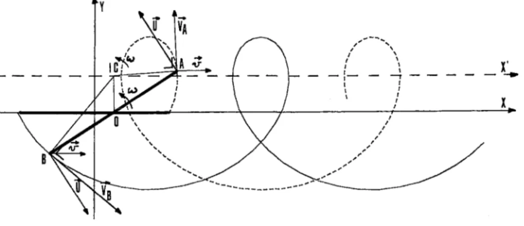
The present study concerns a rotary tiller with a vertical axis, fitted with a crumbier roller, as represented in Fig. 1. Any point on the rotor travels on a path which is a combination of the machine forward motion and the distance from the rotational axis to the point of interest. Assuming that the starting point is with the rotor axis at the origin of the reference axis, the parametric equations which describe the path of extremity points A and B of the rotor are (Fig. 2)
where R = rotor radius; t = time; v = machine forward velocity; ω = angular velocity of rotor, positive when the
rotor rotation is counterclockwise; ωt = displacement angle; at t = 0, ωt is along the x-axis.
These equations can easily be programmed for a graphical representation of the path of the tines, showing the effects of changes in kinematic parameters.
A useful approach for analysing the kinematics of a rotary tiller arises from the location of instant centres of velocity. Instantaneously, all points in a rigid body have the same angular velocity about the instant centre (IC). Considering Fig. 2, the IC of Rotor AB is located at the intersection of the drawn lines perpendicular to the velocities of A and O (or B and O).
The velocity of O is
v
r
, forward motion of the machine.The velocity of A is
V
Ar
, which is obtained by composition of forward velocity
v
r
and peripheral velocityU
r
The magnitude of the velocity at any point of the rotor is the product of the radial distance to the point from IC times the angular velocity
ω
r
. Hence, we can write for the point 0, centre of the rotorwhere a = a constant with units of length. From this, knowing that
v
r
andω
r
are constants when the machine travels at uniform speed, it follows that α is constant and that IC always lies on a straight line ox' parallel to x-axis, with y=α as the equation. As, by definition, at IC, the elements of the rigid body have only angular velocity (at this point they have no linear velocity relative to each other), one may consider that the path of a tine is similar to that of a circle rolling without any slip on the x' -axis i.e. it is a cycloid.
The equations of this cycloid with reference to the x' and y axes are
(4)
If λ= 1, we have a=R. When λ is higher, the cycloids become more closed, corresponding to closer passages of rotating tines in the soil, while on the other hand they are farther spaced with smaller values of λ (Fig. 3). λ> 1 is the most frequently encountered case with rotary tillers. For a given value of R, an increasing λ is obtained by decreasing the machine forward speed or increasing the angular speed of the rotor. In practice, the former is varied by the tractor gearbox and the latter is effected by the selection of gears in the bevel box assembly and/or sprockets in the chain drive assembly (for constant engine speed).
The crumbler roller fitted to the rotary cultivator completes the action of the rotors. It is intended to break surface clods, improve consolidation and level out the seedbed. When the implement moves forward at a small speed, the points of contact between the soil and the bars of the roller are spaced by 2πr/n where r is the radius of the roller and n the number of bars. At higher speeds, the roller is driven with a negative slip and the points of contact between soil and roller become further apart, ensuring a decrease in soil pulverization and consolidation.
Fig. 1. Rotary tiller with vertical axis and following packer.
Fig. 2. Graph of the path of the two extremity points of the rotor, x is the direction of machine forward motion.
Fig. 3. Graph of the paths of the tines belonging to three contiguous rotors (above, λ=3.77 and below λ =2.34).
CHARACTERIZATION OF SOIL STRUCTURE CREATED BY A ROTARY CULTIVATOR
From the above considerations, it appears that a high value of λ should correspond to greater alteration of soil structure and, on the other hand, a decrease in λ leads to a diminution in soil break-up.
An experiment was designed with the aim of comparing soil structures created by the rotary cultivator, working at two different values of λ. The radius of the rotor was 0.16m and in the first case, the machine speed v= 1.8 m
s-1 and ω=26.3 rad s-1 and in the second case v= 1.3 m s-1 and ω=30.6 rad s-1. This gives λ=2.34 and 3.77, respectively. The soil studied can be described as a silt loamy soil with a textural B horizon (Aba) relating to the series level of the Belgian Soil Map in which the three main letters successively represent the nature of parent material or the texture, the moisture class and the profile development. This identification corresponds to a brown soil or a "hapludalf". The composition of the soil is given in Table 1. The results presented here are from an experiment conducted in April 1985, when the moisture content was 16% in the top layers. The soil was tilled conventionally. After ploughing in February 1985, a spring-tine cultivator was used to shatter the soil in April 19 8 5 to a depth of 15 cm. Increased pulverization was obtained by a rotary cultivator to a depth of 10 cm. This treatment was followed by the passage of a ridged roller, improving consolidation, before the sowing of beets. Ten undisturbed samples were collected from the Ap horizon of each set of plots using tubes of 10 cm diameter, 12 cm height and 3 mm wall thickness. This was done before and after the passage of the rotary cultivator, and after the passage of the sowing machine.
TABLE 1:General composition of the studied soil
Sand >0.050 (mm) 5.0%
Silt 0.002-0.050 (mm) 79.0%
Clay <0.002 (mm) 16.0%
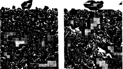
The samples were dried at 40 °C and, according to Murphy (1982), for a low content of clay and organic matter, this low temperature ensures the departure of water without altering soil structure. When dried, the samples were impregnated in a vacuum with the aim that the resin fill the smallest pores possible. The proportion of the resin-hardener-white colour mix was adjusted to produce a good compromise between the viscosity of the mix (a low viscosity allows a good fining of the voids and is obtained with a small proportion of hardener) and the time of hardening (this is shorter when the proportion of hardener increases). A white pigment was added to the mix. The time needed to obtain hard samples varied between 3 and 4 weeks. Once the samples were hard, they were cut vertically at the middle and, thanks to the white colour, the distribution of voids and aggregates was clearly visible. Photographs of sawn sections of the samples were prepared for analysis by a Quantimet 720 image-analysing computer (80x64 mm). The initial sample size was thus reduced. About 18 mm was removed on each side of the sample and the bottom was not taken into account. An example of the photographs is given in Fig. 4. Compared to the method used by Jongerius et al. (1972), Ismail (1975) and Pagliai et al. (1984), who analysed soil structure from transparent photographs of soil, the technique used is not heavy. It directly supplies a view of the whole tilth considered and the resolution obtained is still good; the detection of pore sizes > 100 µm is possible, which is adequate to compare soil tillage performed with different implements.
Fig. 4. Typical photographs of the upper sections of tilth produced by a spring-tine cultivator, rotary tillers (on
RESULTS OF PORE ANALYSES
The pore complex is identified thanks to the white colour in the resin, leading to easy quantification by means of measurements including the total porosity, area and size distribution of pores.
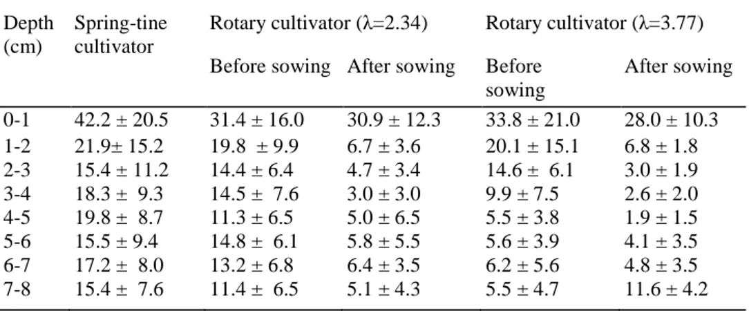
Total porosity is defined here as the proportion of white pixels to total pixels in the scene. The evolution of the total porosity with depth is computed for layers of 1 cm thickness, before and after the passage of rotary cultivators, and after the passage of a planter. Mean values and standard deviations are reported in Table 2. It should be noticed that the porosity value estimated in this way need not be the same as porosity measured by physical tests because it corresponds to a 2-dimensional picture. However, useful information is supplied about the complexity of pore patterns in soil which cannot be obtained by the usual methods. This complexity is reflected by the area and form distribution of pores which determine various physical properties important to plants. They especially affect water infiltration rate and storage capacity. The area distribution of pores is computed by considering two layers in the studied section of the samples: 0-3 and 3-8 cm. The results are presented in Fig. 5. To obtain the best information from the figure, the scale of area is stopped at 1.5 mm2, although some pores have sizes larger than a few millimetres. According to the treatments, pores < 1.5 mm2 correspond to 75-95% of the distribution. This will be discussed later.
The shape of a pore is measured by using a coefficient factor, C, which is represented by
where S is the pore area observed and P is the perimeter. For elongated pores (length = 10xwidth), this ratio is <0.60, while for very rounded pores, it is ~ 1, as indicated in Fig. 6. The form coefficient distributions of pores are given in Fig. 7.
TABLE 2 : Evolution of soil porosity with depth and with the treatments (%) Depth
(cm)
Spring-tine cultivator
Rotary cultivator (λ=2.34) Rotary cultivator (λ=3.77) Before sowing After sowing Before
sowing After sowing 0-1 42.2 ± 20.5 31.4 ± 16.0 30.9 ± 12.3 33.8 ± 21.0 28.0 ± 10.3 1-2 21.9± 15.2 19.8 ± 9.9 6.7 ± 3.6 20.1 ± 15.1 6.8 ± 1.8 2-3 15.4 ± 11.2 14.4 ± 6.4 4.7 ± 3.4 14.6 ± 6.1 3.0 ± 1.9 3-4 18.3 ± 9.3 14.5 ± 7.6 3.0 ± 3.0 9.9 ± 7.5 2.6 ± 2.0 4-5 19.8 ± 8.7 11.3 ± 6.5 5.0 ± 6.5 5.5 ± 3.8 1.9 ± 1.5 5-6 15.5 ± 9.4 14.8 ± 6.1 5.8 ± 5.5 5.6 ± 3.9 4.1 ± 3.5 6-7 17.2 ± 8.0 13.2 ± 6.8 6.4 ± 3.5 6.2 ± 5.6 4.8 ± 3.5 7-8 15.4 ± 7.6 11.4 ± 6.5 5.1 ± 4.3 5.5 ± 4.7 11.6 ± 4.2
Fig. 5. (a) Area distribution of pores after the passage of the rotary cultivator and sowing machine ( λ =3.77).
(b) Area distribution of pores after the passage of the rotary cultivator and sowing machine (λ =2.34).
Fig. 7. (a) Form distribution of pores after the passage of a rotary cultivator and sowing machine (λ=3.77). (b)
Form distribution of pores after the passage of a rotary cultivator and sowing machine (λ=2.34).
DISCUSSION
The loosening created by the spring-tine cultivator essentially results from the creation of internal rupture surfaces, the lifting of soil blocks and their falling after the passage of the tines. This effect is emphasized by the flexibility and vibration of spring steel tines. From Table 2, it appears that soil porosity resulting from this treatment is quite high, but very irregular, as indicated by large standard deviations. It is also interesting to point out the decrease in porosity with depth which may be attributed to the sorting effect of the implement, resulting in the falling of small clods below and between larger ones.
In the action of rotary cultivators, dynamic forces play an important role. Soil clods are broken up by the impact suddenly applied by a rotating tine and they transmit a part of the shock to their neighbours, which are split in turn. Hence cracks are propagated in the environment. The main result from the action of the rotary cultivator is a significant decrease in total soil porosity in the layers located beneath 3-cm depth. This is especially noticeable when λ = 3.77. In this case, the intensive soil pulverization created by the rotors is followed by an important consolidation by the crumbier roller. This confirms the theoretical developments of the above paragraphs. Compared to the results given by the spring-tine cultivator, an improvement in porosity homogeneity is also obtained by the rotary cultivator, as indicated by the values of the standard deviations of Table 2, which are smaller in the latter case.
The action of the ridger roller and the planter can also be pointed out. Data from Table 2 indicate that a strong consolidation has occurred, except for the top layer. Differences in structure of the resulting tilth between plots corresponding to λ = 2.34 and 3.77 remain strong at 3-8-cm depth.
The area distribution of pores shows a highest proportion of small pores (< 0.3 mm2) in the second case and this is particularly noticeable in the layer comprised between 3- and 8-cm depth. The greater homogeneity of the soil porosity obtained with λ = 3.77 is also confirmed. The proportion of pores < 1.5 mm2 is 81.0 and 85.9% for the 0-3- and 3-8-cm layers, respectively, when λ = 2.34, while it is 84.9 and 94.7%, respectively, when λ = 3.77. From the computations relative to the size distribution of pores, it appears that the most frequently encountered pores have a form factor between 0.8 and 0.9 in the top layer as well as in deeper layers. One may consider that > 70% of the pores have a C value between 0.7 and 1, i.e. they are rather well rounded.
A smaller total mean porosity which is more homogeneous thus results when using a rotary cultivator with a higher ratio of peripheral to forward velocity. Are these conditions favourable for plant germination? Two elements of the answer may be suggested: small seeds, like sugar beet seeds, need close contact with soil to germinate and thus a fine structure is favourable. On the other hand, a seedbed constituted of too many smaller sized clods presents the risk of creating soil crusts in certain circumstances.
CONCLUSION
Analysis of the motion of a rotary cultivator indicates that using it with a higher ratio of peripheral to forward velocity leads to closer passages of rotating tines in the soil. A smaller total mean porosity that is more homogeneous results. These differences remain noticeable after the operation of the ridger roller and planter. Further investigation should be useful to optimize the rotary cultivator kinematic parameters in relation to plant growth and climatic stresses. The technique, which consists of impregnating soil samples with polyester resin and analysing them by means of an image-analysing computer, is particularly useful for putting tillage effects on a quantitative basis.
REFERENCES
Dexter, A.R., 1976. Internal structure of tilled soil. J. Soil Sci., 27: 267-78.
Dexter, A.R., 1979. Prediction of soil structure produced by tillage. J. Terramech., 16:117-127.
Hendrick, J.G. and Gill. W.R., 1978. Rotary tiller design parameters, V: Kinematics, Trans. ASAE, 14: 658-660. Ismail, S.N.A., 1975. Micromorphometric soil porosity characterization by means of electro-optical image analysis (Quantimet 720). Soil Surv. Pap. No. 9, Neth. Soil Surv. Inst, Wageningen, 104 pp.
Jongerius, A., Schoonderberbeek, D. and Jager, A., 1972. The application of the Quantimet 720 in soil micromorphometry. Microscope, 20:243-254.
Kinzel, G.L., Holmes, R. and Huber, S., 1981. Computer graphics analysis of rotary tillers. Trans. ASAE, 20:1392-1395. Murphy, C.P., 1982. A comparative study of three methods of water removal prior to resin impregnation of two soils. J. Soil Sci., 33:719-735.
Pagliai, M., La Marca, M., Lucamante, G. and Genovese, L., 1984. Effects of zero and conventional tillage on the length and irregularity of elongated pores in a clay loam soil under viticulture. Soil Tillage Res., 4:433-444.