HAL Id: hal-03164071
https://hal.archives-ouvertes.fr/hal-03164071
Submitted on 29 Mar 2021
HAL is a multi-disciplinary open access
archive for the deposit and dissemination of
sci-entific research documents, whether they are
pub-lished or not. The documents may come from
teaching and research institutions in France or
abroad, or from public or private research centers.
L’archive ouverte pluridisciplinaire HAL, est
destinée au dépôt et à la diffusion de documents
scientifiques de niveau recherche, publiés ou non,
émanant des établissements d’enseignement et de
recherche français ou étrangers, des laboratoires
publics ou privés.
Experimental Demonstration
M. Smierzchalski, F.F. Manzillo, M. del Mastro, N. Capet, B. Palacin, R.
Sauleau, Mauro Ettorre
To cite this version:
M. Smierzchalski, F.F. Manzillo, M. del Mastro, N. Capet, B. Palacin, et al.. A Novel Dual-Polarized
Continuous Transverse Stub Antenna Based on Corrugated Waveguides - Part II: Experimental
Demonstration. IEEE Transactions on Antennas and Propagation, Institute of Electrical and
Elec-tronics Engineers, 2021, 69 (3), pp.1313-1323. �10.1109/TAP.2020.3037809�. �hal-03164071�
A Novel Dual-Polarized Continuous Transverse
Stub Antenna Based on Corrugated Waveguides
-Part II: Experimental Demonstration
Maciej ´Smierzchalski, Francesco Foglia Manzillo, Member, IEEE, Michele Del Mastro, Nicolas Capet, Baptiste
Palacin, Ronan Sauleau, Fellow, IEEE, and Mauro Ettorre, Senior Member, IEEE
Abstract—We present the experimental validation of the dual-mode, polarization-agile parallel-fed continuous transverse stub (CTS) antenna architecture introduced in Part I of this two-part paper. The Ka-band dual-mode CTS array described in Part I is characterized when it radiates horizontal and vertical polariza-tion. To this end, it is combined with two different quasi-optical beamformers operating in a quasi–transverse electromagnetic (quasi-TEM) and in a quasi-transverse electric (quasi-TE1) mode,
respectively. The scanning capabilities of both multibeam antenna systems are demonstrated. The CTS array and its feed network comprising corrugated parallel-plate waveguides (CPPWs) are fabricated by additive manufacturing. Measurements show that the dual-polarized CTS antenna works between 29 GHz and 32 GHz in a field of view of about45◦
, achieving a peak gain of 31.3 dBi and very low cross-polarization. These promising results pave the way for the realization of dual-circularly polarized beam-scanning antennas with application to broadband and compact Ka-band ground terminals.
Index Terms—dual-polarization antennas, multibeam anten-nas, satellite communications, aperture antennas.
I. INTRODUCTION
In Part I [1] of this two-part paper, a novel dual-polarized parallel-fed CTS antenna architecture has been introduced. It comprises a single radiating aperture (an array of long slots) and a dual-mode corporate-feed network based on CPPWs. The operation of the CPPWs and the design trade-offs have been analyzed. The design of an eight-element array operating in Ka-band has been presented and numerically validated.
This work has been funded in part by the Centre National d’Études Spatiales (CNES), in part by the European Union through the European Regional Development Fund and in part by the French Region of Brittany, Ministry of Higher Education and Research, Rennes Métropole and Conseil Départemental 35 through the CPER Project STIC & Ondes.
(Corresponding author: Francesco Foglia Manzillo).
M. ´Smierzchalski was with Univ Rennes, CNRS, IETR (Institut d’Électronique et des Technologies du numéRique), UMR 6164, F-35000 Rennes. He is now with Atos, 95877 Bezons, France and also with Univ. Grenoble Alpes, CEA, Leti, F-38000 Grenoble, France (e-mail: ma-ciej.smierzchalski@cea.fr).
F. Foglia Manzillo was with Univ Rennes, CNRS, IETR (Institut d’Électronique et des Technologies du numéRique), UMR 6164, F-35000 Rennes. He is now with Univ. Grenoble Alpes, CEA, Leti, F-38000 Grenoble, France (e-mail: francesco.fogliamanzillo@cea.fr).
M. Del Mastro, R. Sauleau and M. Ettorre are with Univ Rennes, CNRS, IETR (Institut d’Electronique et des Technologies du numéRique), UMR 6164, F-35000 Rennes (e-mails: {michele.delmastro, ronan.sauleau, mauro.ettorre}@univ-rennes1.fr).
N. Capet and B. Palacin are with the Antenna Department, Centre Na-tional d’Études Spatiales (CNES), Toulouse 31401, France (e-mails:
nico-(a)
(b)
Fig. 1. View of the two characterized systems. The dual-polarized CTS array is connected to (a) a quasi-TEM and (b) a quasi-TE1pillbox beamformer.
In this Part II, we report the experimental validation of the concept and prove a significant bandwidth enhancement over state-of-the-art polarization-agile CTS antennas [2]–[5]. The latter ones rely on cross-connected single-mode traveling-wave arrays, each fed by an independent beamformer, and are mainly suited for narrowband applications. Their scan-ning performance is limited by the mutual coupling of the two orthogonal arrays, which increases with the scan angle. Therefore, motorized phase-shifting surfaces (PSSs) are often stacked on the aperture of CTS arrays to achieve at the same time beam scanning and polarization control [5], [6]. On the other hand, we show in this work that by exciting a single array with two orthogonal modes, dual-polarization and scanning capabilities in one plane can be simultaneously achieved without any moving parts.
As opposed to [2]–[5], the architecture we present is suit-able to be excited by a single dual-polarized line source at the input of the dual-mode CPPW corporate-feed network. Possible designs synthesizing such a line source may rely on dual-polarized slotted waveguide arrays [7], [8]. As an alternative, the dual-polarized array could be excited by a dual-mode quasi-optical system, e.g. a pillbox coupler de-signed for supporting the two antenna modes, illuminated by orthogonally polarized feeds. The specific design of the line
instead on the proof of concept, on the fabrication technology and on the characterization of the scanning performance of the stand-alone antenna in Ka-band. Therefore, the antenna is tested under quasi-TEM and quasi-TE1 mode excitation, respectively, using two separate pillbox beamformers [9], [10]. This choice does not affect the conclusions of this paper. The two antenna systems under test are illustrated in Fig. 1. They radiate linearly-polarized fields which, in what follows, will be referred to as horizontal (H) or vertical (V) when the CTS array is fed by the TEM mode (see Fig. 1a) or the quasi-TE1 mode (see Fig. 1b), respectively.
Though widely used in combination with CTS antennas [11]–[13], these beamformers have been proposed almost ex-clusively for quasi-TEM PPW mode operation in the literature [9], [10]. A pillbox coupler based on rectangular waveguides and operating on the TE10mode was presented in [14]. Design solutions to launch and properly guide a quasi-TE1 mode in a PPW beamformer are here discussed.
The two antenna systems of Fig. 1 are designed to attain approximately the same beam pointing directions at 30 GHz, so that the scanning performance for H- and V- polariza-tion can be fairly compared. Each beamformer comprises seven feeds corresponding to a specific scanned beam in the yz-plane. The dual-mode CTS array is fabricated using stereolithography (SLA), whereas computer numerical control (CNC) milling is employed for the beamformers. Dedicated transitions interconnect the CTS array to both beamformers.
Measurements prove that the dual-polarized CTS antenna works between 29 GHz and 32 GHz achieving a cross-polarization discrimination (XPD) higher than 24 dB for both polarizations. Although the dual-mode CTS array was opti-mized for broadside radiation [1], good scanning performance are demonstrated in a field of view of about 45◦ between 29 GHz and 32 GHz.
The paper is organized as follows. The design and perfor-mance of the beamformers are described in Section II. The impact of beamformers and related transitions on the overall scanning performance is analyzed in Section III. The fabrica-tion of the prototypes and the accuracy of the SLA process are discussed in Section IV. An extensive characterization is presented in Section V. Conclusions are drawn in Section VI. II. PILLBOX BEAMFORMERS:DESIGN AND PERFORMANCE
A. Architecture overview
Both quasi-TEM and quasi-TE1 beamformers (see Fig. 1) are based on a quasi-optical architecture comprising a pillbox coupler [9], [10], [14]. They consist of two stacked hollow PPWs, each of height h0, coupled by a 180◦ bend contouring a parabolic reflector. They are fed by sectoral horns and provide at the output guided modes with planar wavefronts. The heights of the PPWs in the quasi-TEM and quasi-TE1 beamformer are set to hT EM = 0.4λ0 = 4 mm and hT E = 0.7λ0 = 7 mm, respectively, where λ0 is the wavelength at 30 GHz. The quasi-TEM and quasi-TE1 mode have different propagation constants in the beamformers,
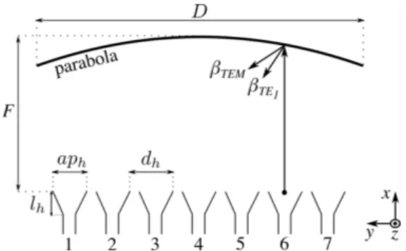
Fig. 2. Schematic top view and main geometrical parameters of the quasi-optical beamformers.
Table 1. MAIN DIMENSIONS(IN MILLIMETERS) OF THE QUASI-OPTICAL BEAMFORMERS DT EM DT E FT EM FT E aph,T EM aph,T E dh 300 300 180 150 25 25 25 βT E1 = q k2 0− (π/hT E) 2
[15]. Thus, the electrical lengths from the feeding horns to the reflectors of the beamformers are different. If the beamformers have same geometry (i.e. same focal lengths, diameters of the reflectors and feeds), the radiated beams corresponding to homologous horns would point to different angles [16]. In this work, instead, both quasi-optical systems were designed to form seven beams, targeting the following pointing directions in the yz-plane at 30 GHz: 0◦,±7.5◦,±15◦,±22.5◦. To this end, an in-house tool based on geometrical optics (GO) [12], [17] was used. It computes, for each feed, the phase distribution along y-axis of the field reflected by the parabola at an interface between the upper PPW, i.e. a medium characterized by the wavenumber βT EM or βT E1, depending on the propagating mode, and free space. In a first approximation, that is the phase distribution along each slot of the CTS array, which allows one to determine the scan angles of the radiated beams. For both beamformers, the simplified geometry shown in Fig. 2 was analyzed. The parabolic reflectors of the two beamformers have the same diameters, equal to the length of the radiating slots of the CTS array. The values DT EM = DT E = 30 λ0 = 300 mm were chosen to attain a directivity higher than 33 dBi at 30 GHz for both excitation modes. Seven input horns of aperture
aph,T EM and aph,T E, for the quasi-TEM and the quasi-TE
mode beamformer, respectively, are placed along the y-axis in the focal planes of the reflectors, with a uniform spacing dh. A simple approach was followed to attain the targeted scan range and similar beam pointing directions for both antenna systems. The positions and apertures of the feeds were assumed the same for both beamformers. The spacing among the feeds was set equal to the feed aperture, i.e. aph,T EM = aph,T E = dh. Then, the focal lengths FT EM and FT E and horn aperture were optimized using the GO tool to meet two objectives, for both beamformers. First, attaining an edge taper lower than -10 dB for the broadside beams. Secondly, enforcing that the outermost beams point at ±22.5◦ at 30 GHz. This choice ensures that the scan angles of corresponding beams radiated by the two antennas are very
(a) (b)
(c)
Fig. 3. Geometry of the input section of the quasi-TE1beamformer, featuring
a corrugated transition. (a) Three-dimensional view. (b) Section in xz-plane. (c) Top view.
(a) (b)
Fig. 4. Simulated electric field distribution inside Horn 4 (plane z = hT E/2)
of the quasi-TE1 beamformer. Results obtained (a) without and (b) with
corrugations.
these parameters, the design of the beamformers is finalized with the aid of full-wave simulations.
B. Beamformer design: input section
The quasi-TEM beamformer is based on a standard design discussed in previous works [9], [11], [14]. Therefore, only a few details are given in this paper. The input feeds are H-plane sectoral horns of height hT EM = 4 mm, excited by standard WR28 waveguides. The size of the transverse section of the input waveguide is 3.56 mm × 7.12 mm. The length of the flared section of the horn is lT EMhorn = 25 mm.
On the other hand, several modifications to standard pillbox designs have been introduced for realizing the quasi-TE1 beamformer. These changes are necessary to properly launch and guide the desired mode. With respect to the quasi-TEM beamformer, the input waveguides are rotated by 90◦to launch y-polarized electric fields. The three-dimensional view and cross sections of the horns in the quasi-TE1-mode pillbox are illustrated in Fig. 3. The length of the tapered section of the horn is lT E
horn= 25 mm. The aperture size is 7 mm× 20 mm. Corrugations run on top and bottom walls of the horns, parallel to the xy-plane, as well as on the plates in the PPW transition region at the output of the horns. As illustrated in Fig. 3, the corrugations have rectangular section of width wc = 0.5 mm and height hc = (hT E − hT EM)/2 = 1.5 mm. They are arrayed along y-axis with a constant spacing
−80 −60 −40 −20 0 20 40 60 80 φ (deg) −40 −30 −20 −10 0 Radiation pattern (dB) TE with corrugation TE w/o corrugation TEM
Fig. 5. Simulated far-field radiation patterns of the central horns (see Horn 4 in Fig. 2) inside the PPW regions of the two designed beamformers, at 30 GHz. For the quasi-TE1beamformer, the results relative to the proposed corrugated
horn are compared to those obtained in the absence of corrugations.
Fig. 6. Cross section and main parameters of the pillbox transition between the bottom and top PPWs of each beamformer.
mm beyond the apertures of the horns. Figure 4 compares the magnitudes of the electric field on the plane z = hT E/2 of the structure of Fig. 3 with and without corrugations. The results are obtained from full-wave simulations at 30 GHz, exciting Horn 4 (see Fig. 2) and terminating the PPW by a perfectly matched layer (PML). They clearly demonstrate that the corrugations are necessary for the correct operation of the quasi-TE1 beamformer. If no corrugations are included, the electric field at the discontinuity between the horns tends to propagate along y-axis in the PPW, as shown in Fig. 4a. As a consequence, a significant amount of energy is lost as a lateral parallel-plate mode. On the other hand, the corrugated horn and transition, acting as a hard surface [18], [19], hinder the propagation along y-axis, as shown by the field plot in Fig. 4b. Thanks to the proposed design, the desired cylindrical wavefront is properly launched in the beamformer.
The far-field patterns (xy-plane cut) radiated at 30 GHz in the PPW region of the beamformers are plotted in Fig. 5. The patterns of the quasi-TEM and quasi-TE1 feeds are similar and their half-power beamwidth (HPBW) is about 35◦. For the quasi-TE1 mode, the pattern of the designed feed comprising corrugated sections (see Fig. 3) is compared to that obtained simulating the same structure without corrugations (orange line in Fig. 5). In the absence of corrugation, the pattern is clearly distorted and exhibits higher side lobes and ripples. C. Pillbox coupling transition
The beamformers feature similar 180◦-bends to couple the energy from the bottom PPW to the upper one. In standard
−40 −30 −20 −10 0 10 20 30 40 θ (deg) −40 −30 −20 −10 0 Radiation pattern (dB) Horn 1 Horn 2 Horn 3 Horn 4 GO tool Full-wave sim. (a) −40 −30 −20 −10 0 10 20 30 40 θ (deg) −40 −30 −20 −10 0 Radiation pattern (dB) Horn 1 Horn 2 Horn 3 Horn 4 GO tool Full-wave sim. (b)
Fig. 7. Simulated far-field patterns (xy-plane cut) of the open-ended pillbox beamformers at 30 GHz compared to the results computed using the GO model. (a) Quasi-TEM and (b) quasi-TE1beamformer.
on top of the other so that they are separated by an electrically thin metal layer. The coupling transition is typically realized as a single slot [11], [14] or multiple slots [10] contouring the reflector. However, the realization of these transitions in a thin metal makes the structure fragile. An alternative design is here presented. It eases the fabrication of the beamformers using conventional CNC milling and enhances their mechan-ical robustness. The cross section (xz-plane) of the proposed coupler-type bend is shown in Fig. 6. The region between the PPWs is filled by a metal layer of thickness hS = 3 mm. A double mitered bend is optimized to minimize reflections. The maximum widths of the bends (wslot in Fig. 6) are 6.5 mm and 10 mm for the quasi-TEM and quasi-TE1 beamformer, respectively.
D. Performance of the quasi-optical beamformers
The consistency of the simulated field distributions at the output of the beamformers with the results predicted by GO analysis can be evaluated comparing the corresponding far-field patterns radiated by each beamformer when the upper PPW is open-ended, as in a pillbox antenna [20]. In full-wave simulations, each beamformer is laterally bounded by perfect electric conductors and radiation boundary is enforced on the
27 28 29 30 31 32 33 34 35 Frequency (GHz) 0 5 10 15 20 25 30 35 Scan angle (deg) Horn 1 Horn 2 Horn 3 Quasi-TE1 Quasi-TEM
Fig. 8. Pointing directions in the xy-plane of several beams radiated by the designed pillbox beamformers, assuming they are open-ended. The results are obtained from full-wave simulations. The beams are denoted by the corresponding feed number (see Fig. 2). Quasi-TEM and quasi-TE1 beams
are shown in dashed and solid lines, respectively.
(a) (b)
Fig. 9. Sections (xz-plane) of the output transitions of the (a) quasi-TEM and (b) quasi-TE1beamformers enabling the interconnection to the CTS antenna.
others are terminated by matched loads. The radiation patterns (xy-plane cuts) at 30 GHz are shown in Fig. 7.
The two sets of beams have similar characteristics. The main lobes of the H-polarized beams are slightly wider than the those of corresponding V-polarized beams. For instance, the HPBWs of the broadside beams are 2.8◦ (quasi-TEM mode) and 2.6◦ (quasi-TE1 mode). This is mainly due to the distributions of the fields over the radiating elements. Indeed, the PPWs are realized, in practice, as largely overmoded rectangular waveguides. Whilst the amplitude of the quasi-TE1 mode is uniform along y-axis, that of the quasi-TEM mode varies as a cosine and vanishes on the lateral walls parallel to x-axis.
The scan angles of the simulated pillbox systems are plotted against frequency in Fig. 8. The pointing directions of the quasi-TEM beams are extremely stable in the frequency range of interest. The frequency variations observed for the other beamformer are due to the dispersion of the quasi-TE1 mode, which are nevertheless limited. The differences between the scan angles of homologous H- and V-polarized beams are very small between 29 GHz and 32 GHz.
III. FULL ANTENNA SYSTEMS
A. Beamformer-to-CTS antenna interconnect
The pillbox systems and the CTS antenna are fabricated as independent blocks. Low-loss transitions were designed at the output of each beamformer so that both can be connected to
−40 −30 −20 −10 0 10 20 30 40 θ (deg) −40 −30 −20 −10 0 Normalized pattern (dB) Horn 1Horn 2 Horn 3 Horn 4
Full antenna Stand-alone CTS
(a) −40 −30 −20 −10 0 10 20 30 40 θ (deg) −40 −30 −20 −10 0 Normalized pattern (dB) Horn 1 Horn 2 Horn 3 Horn 4
Full antenna Stand-alone CTS
(b)
Fig. 10. Simulated radiation patterns (yz-cut) at 30 GHz of the full antenna system (dashed lines) and of the stand-alone CTS array (solid lines). In the latter case, the array is excited using the simulated field distribution at the output of the pillbox. (a) Horizontal polarization (quasi-TEM system) and (b) vertical polarization (quasi-TE1 system).
and Fig. 9b, respectively, were adopted. The heights of the output PPWs of the quasi-TEM and quasi-TE1 beamformers are equal to the parameters hT EM and hT Eof the input CPPW of the corporate-feed network [1]. Each transition includes a right-angle bend with a mitered corner which is tuned to gradually transform the input PPW modes into CPPW modes. The simulated reflection coefficients of the transitions, each fed by a single mode, are both less than -20 dB between 27 GHz and 35 GHz.
B. Simulated performance and impact of the beamformers In this subsection, the simulated scanning performance of the two complete antenna systems are compared with the results obtained for the stand-alone dual-mode CTS array described in [1]. This comparison allows one to assess the impact of beamformers and related transitions (see Section III-A) on the radiation patterns and gain. The results for the stand-alone antenna are found by exciting the input of the CPPW feed network (see port T1_P1 in Fig. 13 of [1]) with the simulated field distributions at the output of the corresponding
27 28 29 30 31 32 Frequency (GHz) 26 28 30 32 34 36 Realized gain (dBi)
Horn 1 Horn 2 Horn 3 Horn 4
Full antenna Stand-alone CTS
(a) 27 28 29 30 31 32 Frequency (GHz) 26 28 30 32 34 36 Realized gain (dBi)
Horn 1 Horn 2 Horn 3 Horn 4
Full antenna Stand-alone CTS
(b)
Fig. 11. Simulated peak gain as a function of frequency, for several beams of the full antenna system (dashed lines) and of the stand-alone CTS array (solid lines). In the latter case, the array is excited using the simulated field distribution at the output of the pillbox. (a) Horizontal polarization (quasi-TEM system) and (b) vertical polarization (quasi-TE1 system).
II-D. On the other hand, the data relative to the full antenna systems are obtained from full-wave simulations.
Figure 10 shows the radiation patterns at 30 GHz in the scanning plane (yz-plane), for H- and V-polarization. By virtue of symmetry, only the beams pointing at non-negative angles are reported. Each pattern is normalized to the maximum of the corresponding broadside beam. The patterns relative to complete antenna systems (in dashed lines) exhibit slightly wider beamwidths with respect to those radiated by the stand-alone antenna (in solid lines). This difference and other minor discrepancies on the first SLLs are mainly due to phase aberrations introduced by the transition from the beamformer to the CTS antenna.
The gain is plotted in Fig. 11 as a function of frequency. With reference to the broadside beams, the losses at 30 GHz due to the beamformer and the output transition are about 0.5 dB and 0.8 dB under quasi-TEM and quasi-TE1 mode excitation. The beamformer supporting the quasi-TE1 mode introduces higher losses for all beams in most of the frequency range considered. This can be also observed comparing in Fig. 11a and Fig. 11b the differences between the values of the gain for the full system and the stand-alone CTS antenna.
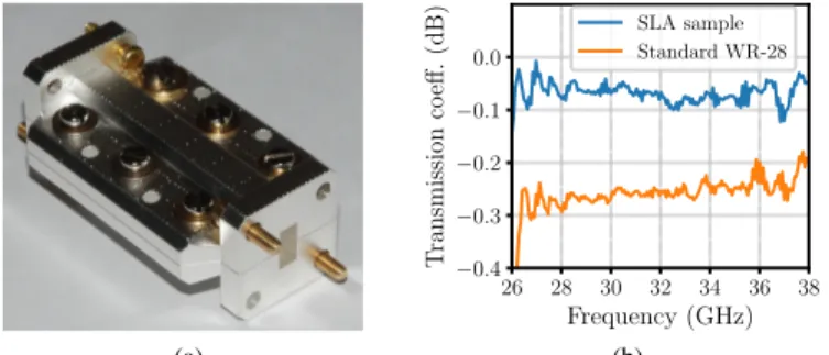
(a) 26 28 30 32 34 36 38 Frequency (GHz) −0.4 −0.3 −0.2 −0.1 0.0 T ransmission co eff. (dB) SLA sample Standard WR-28 (b)
Fig. 12. (a) Picture of the waveguide sample realized by stereolithography and (b) measured transmission coefficient, in blue line, compared to that of a standard WR28 metallic waveguide (orange line).
Fig. 13. Exploded view of the CTS antenna fed by the quasi-TE1 mode
pillbox. The various blocks of the system are highlighted with different colors.
insertion loss does not exceed 1.8 dB between 27.5 GHz and 32 GHz.
The frequency dispersion of the quasi-TE1mode affects the scan loss of the vertically-polarized antenna and the variations of the realized gain in the band, which are greater than the values observed under quasi-TEM operation. The performance degradation is more evident for the scanned beams. The phase aberrations due to the off-focus illumination of the parabolic reflectors of the beamformers are more relevant when the incident mode is quasi-TE1. As a result, the gain drops faster with the scan angle as compared to the case of quasi-TEM excitation. The cut-off frequency increases with the scan angle (see Beam 1 in Fig. 11b). Nevertheless, the results show that the bandwidth is compatible with the requirements of Ka-band SATCOM applications: in both polarization modes, the realized gain of each beam varies less than 2 dB between 28.5 GHz and 32 GHz.
IV. FABRICATION
Milling and electro-erosion techniques are commonly em-ployed, up to E-band, to manufacture CTS antennas based on hollow waveguides [11], [13], [16], [21]. However, these pro-cesses are not suitable for structures comprising corrugations on both vertical and horizontal planes, such as the CPPW feed network. Additive manufacturing techniques are instead suited for this task. Their resolution and tolerances are fine enough for realizing microwave systems at Ka-band. Therefore, the CTS array was realized using stereolithography (SLA). On the
(a)
(b) (c)
Fig. 14. (a) Picture of the CTS antenna fed by the quasi-TEM mode beamformer. Detail of the CPPW feed network fabricated by stereolithography (b) before and (c) after copper plating.
at most one-dimensional corrugations, were fabricated using CNC machining.
A. Accuracy and loss of SLA process
The SLA process shapes a photopolymer resin defining layer by layer its transverse section. The resulting surface roughness affects the microwave performance. In order to evaluate the losses introduced by this process, a standard WR28 waveguide of length 72 mm was fabricated and char-acterized in Ka-band. The fabrication is divided in three main steps: shaping the resin cores, electroless copper plating (10 thick) and successive electroless silver plating (5 µm-thick). The sample, shown in Fig. 12a was manufactured in two sections to achieve a uniform metal plating. These two parts were joint along the waveguide centerline in the E-plane to minimize the impact of possible air gaps. The waveguide was measured using a network analyzer calibrated with a WR28 HP kit. Figure 12b compares the measured transmission coefficient of the waveguide to that of the thru of the calibration kit. The SLA-fabricated sample exhibits an attenuation of about 3.7×10⁻³ dB/mm at 30 GHz. Thanks to the silver plating, it achieves an insertion loss even lower than the standard thru. These results prove that the selected SLA process introduces marginal losses.
B. Prototype assembly
The dual-polarized CTS antenna and the quasi-optical beamformers were fabricated in several blocks and assembled using screws and dowels. The SLA-manufactured radiating
(a) (b)
Fig. 15. Measured reflection coefficients at the input horns when the CTS antenna is fed by: (a) the quasi-TEM or (b) the quasi-TE1beamformer.
A picture of the entire antenna system is shown in Fig. 14a, when the quasi-TEM beamformer is connected to the CTS array. The inputs of the seven feeds of the beamformer are visible in the foreground.
Figures 14b and 14c show one block of the CPPW feed network before and after copper plating, respectively. The longitudinal corrugations can be appreciated. The measured tolerances on the parameters of CPPWs are about ±10 µm.
The CPPW network is filled by foam spacers (in white in Fig. 14a), whose dimensions are guaranteed with a tolerance of 50µm, i.e. λ/20 at 30 GHz. These spacers improve the mechanical stability of the antenna under test. Indeed, the thin and long plastic cores used for the outer plates of the CPPWs tend to bend toward the center and to move off their nominal positions. These flaws slightly modify the sections of the CPPWs and lead a non-uniform power division in the feed network. The use of a more rigid plastic or novel selective laser melting (SLM) processes can mitigate these issues, providing more robust components. At the time of the fabrication of the prototype, the roughness guaranteed by SLM technology was considered unsuited for antenna applications at Ka-band.
V. EXPERIMENTAL RESULTS
The reflection coefficients, shown in Fig. 15, were measured connecting a vector network analyzer to each input horn through a coaxial-to-waveguide transition. The worst results are obtained when the central feeds (Horn 4 in Fig. 2) are excited, since they are located in the focus of the parabolic reflectors. The -10-dB impedance matching band when the antenna is excited by the in-focus horn of the quasi-TEM beamformer ranges from 27 GHz to 32 GHz. The reflection coefficient of the homologous feed of the quasi-TE1 antenna system (see Fig. 16b) is less than −10 dB starting from 28.5 GHz, except for some ripples around 31 GHz. This measurement also shows that the cut-off of the quasi-TE1 mode is at about 26.5 GHz, which is slightly higher than the value computed in the design (about 24.5 GHz for the reference CPPW [1]). This discrepancy can be attributed to the bending of the thin plastic cores of the CPPW structures, discussed in Section IV-B, and to alignment errors in the assembly of the beamformer and the CTS array. As a result, the operating band of the quasi-TE1antenna system is shifted
−40 −30 −20 −10 0 10 20 30 40 θ (deg) −40 −30 −20 −10 0 Normalized pattern (dB) Co-pol. - Meas. Co-pol. - Sim. X-pol. - Meas. X-pol. - Sim. (a) −40 −30 −20 −10 0 10 20 30 40 θ (deg) −40 −30 −20 −10 0 Normalized pattern (dB) Co-pol. - Meas. Co-pol. - Sim. X-pol. - Meas. X-pol. - Sim. (b)
Fig. 16. Measured and simulated co- and cross-polarized patterns at 30 GHz (yz-plane cut) for the broadside beam. The dual-polarized CTS antenna is excited by: (a) the quasi-TEM mode and (b) the quasi-TE1beamformer.
The radiation performance was characterized in the compact antenna test range (CATR) of IETR. The co-polar and cross-polar patterns (yz-plane cut) of the broadside beam at 30 GHz are shown in Fig. 16. Measured results are in good agreement with simulations. Small differences in terms of beamwidth of the main lobe and positions of the dips are observed when the antenna is fed by the quasi-TE1 mode. They are partially caused by the shift of the operating band. The measured values of the HPBW are about 2.4◦ and 2.8◦ for H- and V-polarization, respectively, while the peak cross-polarization levels are less than -37 dB and -28 dB. The higher cross-polarized component when the antenna is fed by the quasi-TE1 mode is due to the beamformer, which may guide residual quasi-TM1 fields, and to the transition to the CPPW feed network.
Figure 17 compares measured and simulated patterns of the scanned beams at 30 GHz. For both polarizations, each beam is normalized to its maximum value. The deviations of measured scan angles from the corresponding simulated values are less than 1◦. They are more relevant for V-polarized beams, as a consequence of the observed shift of the cut-off frequency of the quasi-TE1 mode. The first SLLs increase with the scan angle, due to the off-focus illumination of the beamformers,
−40 −30 −20 −10 0 10 20 30 40 θ (deg) −40 −30 −20 −10 0 Normalized pattern (dB) Horn 1 Horn 2 Horn 3 Horn 4 Measurements Simulations (a) −40 −30 −20 −10 0 10 20 30 40 θ (deg) −40 −30 −20 −10 0 Normalized pattern (dB) Horn 1 Horn 2 Horn 3 Horn 4 Measurements Simulations (b)
Fig. 17. Measured and simulated radiation patterns (yz-plane) of the dual-polarized CTS antenna at 30 GHz when fed by (a) the quasi-TEM mode and (b) the quasi-TE1 beamformer. Each beam is normalized to its maximum.
outermost beams, respectively. The anisotropy of the CPPW is more relevant under quasi-TE1-mode excitation. As a result, the increase of the SLLs with the scan angle is faster for V-polarized beams.
Figure 18 presents the measured realized gain as a func-tion of frequency and elevafunc-tion angle in yz-plane, for both polarizations and beams pointing at non-negative scan angles. The characteristics of the broadside beam are stable over most of the frequency range (27-32 GHz) when the antenna is fed by the quasi-TEM beamformer (see Fig. 18a). The SLLs are, in average, well below −20 dB. The gain dip around 30.6 GHz corresponds to a destructive interference due to phase and amplitude imbalance on the radiating slots, which can be attributed to the aforementioned bending of plastic cores and to misalignment between the beamformer and the radiating section. This explanation is confirmed by the presence at this frequency of asymmetries and high SLLs in the xz-plane cut of the radiation pattern, not shown here for brevity, which is, instead, elsewhere close to the expected sinc-pattern of a uniform array.
The broadside V-polarized beam is shown in Fig. 18e. The gain drops and the SLLs rise in the low edge of the band, as one moves toward the cut-off of the quasi-TE1mode. A similar
Table 2. MEASURED CROSS-POLAR DISCRIMINATION(XPD)OF THE DUAL
-POLCTSANTENNA BETWEEN29 GHZ AND32 GHZ. Horn # Pol. XPD (dB) 29 GHZ 30.5 GHZ 32 GHZ 1 H 19.2 12.6 14.1 V 11.1 13.0 11.0 2 H 27.9 18.5 12.8 V 14.4 19.5 12.7 3 H 29.6 21.7 17.6 V 23.8 23.4 14.6 4 H 39.4 37.2 36.9 V 24.2 24.9 28.1
to the increased input reflection coefficient beyond 31 GHz and to the progressive onset of higher order modes.
The measured peak realized gain of the broadside beams are 31.3 dBi and 30.6 dBi, for H- and V-polarization, respectively. Figures 18a-18d demonstrate that the quasi-TEM antenna system attains low scan losses for all beams, as well as stable performance over the band. The V-polarized antenna exhibits a more pronounced beam squint due to the frequency dispersion of the quasi-TE1 mode. The scan angle varies from 21.1◦ to 23.6◦ between 29 GHz and 32 GHz. The scan loss for the V-polarized outermost beam is 2.8 dB at 30.5 GHz. By comparing Figs. 18e-18h, one can also observe that the cut-off frequency of the quasi-TE1 mode increases when the antenna beam is scanned. These observations are further corrobo-rated by Fig. 19, comparing the measured directivity of the broadside and outermost beams, for both polarizations, against frequency. When the antenna operates on a quasi-TE1 mode, its bandwidth and scan loss degrade with the beam pointing direction at a faster rate. This performance can be improved by engineering the dispersion of the beamformer and of the CPPW feed network under oblique incidence. Nevertheless, although the dual-mode CPPW network has been optimized for broadside radiation, a good performance in a scan range exceeding 45◦has been experimentally demonstrated between 29 GHz and 32 GHz, for both polarizations.
The values of the radiation efficiency at 30 GHz of the full antenna systems, computed as the ratio between measured realized gain and measured directivity, are 80% and 90% for H- and V-polarized broadside beams, respectively. At the same frequency, the values for the outermost beams are 84% (quasi-TEM mode) and 79% (quasi-TE1 mode). These experimental results prove that the proposed dual-polarization shared-aperture design and fabrication technology preserve the characteristic high efficiency of standard CTS arrays.
The measured values of the XPD in this band are reported in Table 2, for non-negative scan angles. The XPD is higher than 11 dB even for the outermost V-polarized beams. These results confirm that the proposed dual-mode antenna system achieves high polarization purity.
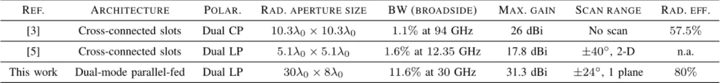
The key figures of merit and features of the antenna presented in this work are compared in Table 3 to the best
(a) (b) (c) (d)
(e) (f) (g) (h)
Fig. 18. Measured gain pattern (cut in yz-plane) as a function of frequency and elevation angle, for the beams pointing at non-negative angles (corresponding to the excitation of Horn 1-4 in Fig. 2). Results obtained when the CTS antenna is fed by: (a)-(d) the quasi-TEM and (e)-(h) the quasi-TE1beamformer.
27 28 29 30 31 32 21 23 25 27 29 31 33
Fig. 19. Measured peak directivity as a function of frequency when the CTS array is excited by the quasi-TEM (solid lines) and quasi-TE1(dashed lines)
beamformer. The results are plotted for the broadside and outermost beams.
the antennas in [3] and [5] rely on two orthogonal, cross-connected series-fed arrays of long slots, each illuminated by a dedicated quasi-optical beamformer supporting the funda-mental TEM mode. Thanks to the parallel-fed architecture, the dual-mode antenna presented in this paper attains, for broadside radiation, a relative -3-dB gain bandwidth which is almost eight times the bandwidth reported in [5]. The modal dispersion intrinsically limits the scan range achievable by the proposed antenna when excited by standard pillbox systems. However, it is important to stress that no beam scanning is demonstrated in [3], whilst the antenna in [5] covers a ±40◦ field of view in elevation, for all azimuth planes, only resorting to a mechanically-rotated Riley prism loading the CTS array. This device further narrows the bandwidth (< 1%) for
off-a ±24◦ scan range leveraging on an architecture suitable for electronic beam switching. The research on dispersion-engineered dual-mode beamformers could lead to a significant enhancement of the field of view attained in the present work.
VI. CONCLUSIONS
This two-part paper introduced, described and experimen-tally validated a novel dual-polarized CTS antenna archi-tecture. Polarization agility is achieved thanks to the dual-mode operation of the CTS array and related feed network which is based on expressly designed corrugated waveguides. Key advantages over existing dual-polarized CTS antennas include broadband operation and the use of a single radiating aperture and feeding system instead of two orthogonal arrays individually excited by a dedicated beamformer. Moreover, the proposed architecture allows for beam-scanning in one plane without any add-on motorized phase shifting surface. As a first proof of concept, the dual-polarization and scanning capabili-ties of a Ka-band eight-element array were characterized using two separate pillobox beamformers, supporting a quasi-TEM and a quasi-TE1 mode, respectively. The CPPW-based CTS array was fabricated by means of a low-cost SLA process.
The measured broadside beams exhibits stable characteris-tics and comparable realized gain values between 29 GHz and 32 GHz. Such a wide relative bandwidth (≈ 11.6%) largely exceeds those attained by state-of-the-art dual-polarized CTS arrays which are penalized by the traveling-wave radiation mechanism. In this band, the peak realized gain are 31.3 dBi and 30.6 dBi, while the crosspolar components are less than -37 dB and -28 dB, under quasi-TEM and quasi-TE1excitation, respectively. Though designed for broadside radiation, the dual-polarized array achieves a good performance in a range
Table 3. COMPARISON WITH STATE-OF-THE-ART POLARIZATION-AGILECTSANTENNAS.
REF. ARCHITECTURE POLAR. RAD.APERTURE SIZE BW (BROADSIDE) MAX.GAIN SCAN RANGE RAD.EFF. [3] Cross-connected slots Dual CP 10.3λ0× 10.3λ0 1.1% at 94 GHz 26 dBi No scan 57.5%
[5] Cross-connected slots Dual LP 5.1λ0× 5.1λ0 1.6% at 12.35 GHz 17.8 dBi ±40◦, 2-D n.a.
This work Dual-mode parallel-fed Dual LP 30λ0× 8λ0 11.6% at 30 GHz 31.3 dBi ±24◦, 1 plane 80%
GHz, achieving a XPD higher than 11 dB in any case. The performance is partially limited by fabrication and assembly inaccuracies, such as the bending of CPPWs and misalignment errors. Alternative 3-D printing techniques, such as selective laser melting (SLM), not available at the time of fabrication, could further enhance the reliability of the process and the antenna performance.
The experimental results reveal the potential of the concept for future compact SATCOM antennas combining broadband coverage with switchable circular polarization.
ACKNOWLEDGMENT
The authors are grateful to Xavier Morvan (IETR) for his help in manufacturing and assembling the prototype, and Dr. Laurent Le Coq (IETR) for the antenna characterization.
REFERENCES
[1] M. ´Smierzchalski, F. Foglia Manzillo, M. Del Mastro, N. Capet, B. Palacin, R. Sauleau, and M. Ettorre, “A novel dual-polarized con-tinuous transverse stub antenna based on corrugated waveguides - Part I: Operating principle and design,” submitted to IEEE Trans. Antennas Propag., Sept. 2019.
[2] W. H. Henderson and W. W. Milroy, “Wireless communication appli-cations of the continuous transverse stub (CTS) array at microwave and millimeter wave frequencies,” in IEEE/ACES Int. Conf. Wir. Comm. Appl. Comp. Electromag.s, Apr. 2005, pp. 253–256.
[3] Y. J. Cheng, J. Wang, and X. L. Liu, “94 GHz substrate integrated waveguide dual-circular-polarization shared-aperture parallel-plate long-slot array antenna with low sidelobe level,” IEEE Trans. Antennas Propag., vol. 65, no. 11, pp. 5855–5861, Nov. 2017.
[4] T. Lou, X.-X. Yang, L. Li, and E. Abubaker, “A flat dual-polarized continuous transverse stub antenna array based on substrate integrated waveguide,” in 12th Eur. Conf. Antennas Propag. (EuCAP), Apr. 2018, pp. 1–3.
[5] T. Lou, X. Yang, H. Qiu, Z. Yin, and S. Gao, “Compact dual-polarized continuous transverse stub array with 2-D beam scanning,” IEEE Trans. Antennas Propag., vol. 67, no. 5, pp. 3000–3010, May 2019. [6] W. W. Milroy, “Inscribed polarizer array for polarization diverse
appli-cation,” Patent U.S. Patent 9 941 594 B2, 4 10, 2018.
[7] A. Dorlé, R. Gillard, E. Menargues, M. Van Der Vorst, E. De Rijk, P. Martín-Iglesias, and M. García-Vigueras, “Additive manufacturing of modulated triple-ridge leaky-wave antenna,” IEEE Antennas Wirel. Propag. Lett., vol. 17, no. 11, pp. 2123–2127, Nov. 2018.
[8] X. Lu, S. Gu, X. Wang, H. Liu, and W. Lu, “Beam-scanning continuous transverse stub antenna fed by a ridged waveguide slot array,” IEEE Antennas Wirel. Propag. Lett., vol. 16, pp. 1675–1678, 2017. [9] T. Teshirogi, Y. Kawahara, A. Yamamoto, Y. Sekine, N. Baba,
and M. Kobayashi, “Dielectric slab based leaky-wave antennas for millimeter-wave applications,” in Proc. IEEE Antennas Propag. Soc. Int. Symp., vol. 1, Jul. 2001, pp. 346–349.
[10] M. Ettorre, R. Sauleau, and L. L. Coq, “Multi-beam multi-layer leaky-wave SIW pillbox antenna for millimeter-leaky-wave applications,” IEEE Trans. Antennas Propag., vol. 59, no. 4, pp. 1093–1100, Sept. 2011. [11] M. Ettorre, F. Foglia Manzillo, M. Casaletti, R. Sauleau, L. Le Coq, and
N. Capet, “Continuous transverse stub array for Ka-band applications,” IEEE Trans. Antennas Propag., vol. 63, no. 11, pp. 4792–4800, Nov. 2015.
[12] F. Foglia Manzillo et al., “A wide-angle scanning switched-beam antenna system in LTCC technology with high beam crossing levels for V-band communications,” IEEE Trans. Antennas Propag., vol. 67, no. 1, pp.
[13] T. Potelon, M. Ettorre, and R. Sauleau, “Long slot array fed by a nonuniform corporate feed network in PPW technology,” IEEE Trans. Antennas Propag., vol. 67, no. 8, pp. 5436–5445, Aug. 2019. [14] V. Mazzola and J. E. Becker, “Coupler-type bend for pillbox antennas,”
IEEE Trans. Microw. Theory Techn., vol. 15, no. 8, pp. 462–468, Aug. 1967.
[15] D. M. Pozar, Microwave engineering. John Wiley & Sons, 2012. [16] W. W. Milroy, “The continuous transverse stub (CTS) array: basic theory,
experiment, and application,” in Proc. Antenna Appl. Symp., vol. 2, Sep. 1991, pp. 253–283.
[17] E. Girard, G. Valerio, M. Ettorre, R. Sauleau, and H. Legay, “Physical-optics analysis and design of a beam-forming network coupled to an imaging-system configuration for ka-band satellite applications,” in 9th Eur. Conf. Antennas Propag. (EuCAP), Apr. 2015, pp. 1–5.
[18] E. Lier and P.-S. Kildal, “Soft and hard horn antennas,” IEEE Trans. Antennas Propag., vol. 36, no. 8, pp. 1152–1157, Aug. 1988. [19] P.-S. Kildal, “Artificially soft and hard surfaces in electromagnetics,”
IEEE Trans. Antennas Propag., vol. 38, no. 10, pp. 1537–1544, Oct. 1990.
[20] E. L. Holzman, “Pillbox antenna design for millimeter-wave base-station applications,” IEEE Antennas Propag. Mag., vol. 45, no. 1, pp. 27–37, Feb. 2003.
[21] Y. You, Y. Lu, Q. You, Y. Wang, J. Huang, and M. J. Lancaster, “Millimeter-wave high-gain frequency-scanned antenna based on waveg-uide continuous transverse stubs,” IEEE Trans. Antennas Propag., vol. 66, no. 11, pp. 6370–6375, Nov. 2018.
Maciej ´Smierzchalski was born in Gdánsk, Poland, in 1983. He received the B.Sc. and M.Sc. degrees the Gdansk University of Technology, Gdánsk in 2008, and the Ph.D. degree in signal processing and telecommunications from the University of Rennes 1, Rennes, France, in 2014. In 2006, he was a visiting Student at the Ecole Centrale de Lille, Lille, France. He was with NXP Semiconductors, Caen, France and Radiocom, Gdánsk, Poland respectively in 2007 and 2009. In 2012, he was a visiting Ph.D. Student at the University of Siena, Siena, Italy. From 2014 to 2016, he was a Post-Doctoral Fellow with the Institut d’Electronique et de Telécommunications de Rennes (IETR), Université de Rennes 1, Rennes, France. Since 2016 he has been with the French Alternative Energies and Atomic Energy Commission (CEA) Grenoble and ATOS Grenoble, France. His current research interests include the analysis and design of leaky-wave antennas, periodic structures, wideband arrays, near-field focusing techniques and bio-electromagnetism.
Dr. ´Smierzchalski was a recipient of the Best Innovation Award at the 39th European Space Agency Antenna Workshop 2018 in Noordwijk, The
Francesco Foglia Manzillo (Member, IEEE) re-ceived the B.Sc. and M.Sc. degrees (cum laude) in electronics engineering from the University of Naples Federico II, Naples, Italy, in 2010 and 2012, respectively, and the Ph.D. degree in signal process-ing and telecommunications from the University of Rennes 1, Rennes, France, in 2017. In 2012, he was an Intern at the Electronic Research Laboratory, Delft University of Technology, Delft, The Nether-lands, and at NXP Semiconductors, Eindhoven, The Netherlands. In 2016, he spent six months as a Vis-iting Ph.D. Student at the Radiation Laboratory, University of Michigan, Ann Arbor, MI, USA. Since July 2017, he has been with the French Alternative Energies and Atomic Energy Commission, Laboratory of Electronics and Information Technologies (CEA-Leti), Grenoble, France.
His research interests include the analysis, synthesis, and design of antenna arrays, quasi-periodic structures (transmitarrays, frequency-selective surfaces, and polarization converters), numerical modeling, and the integration of millimeter-wave antenna systems.
Dr. Foglia Manzillo was a co-recipient of the Best Innovation Award at the 39th European Space Agency Antenna Workshop in 2018.
Michele Del Mastro was born in Avellino, Italy, on July 25th, 1992. He received the M. Mus. degree in clarinet from the Conservatorio di Musica ‘D. Cimarosa’, Avellino, Italy, in 2011, and the M.Sc. degree summa cum laude in electronics engineering from the Università degli Studi di Napoli ‘Federico II’, Naples, Italy, in 2017. Since October 2017, he has been pursuing the Ph.D. degree in electrical engineering at the Institut d’Électronique et des Technologies du numéRique (IETR), Université de Rennes 1, Rennes, France. In 2016, he joined the Electronic Research Laboratory, Delft University of Technology, Delft, The Netherlands, where he held a position as Intern. From May to October 2019, he was Visiting Ph.D. Student with the Radiation Laboratory, University of Michigan, Ann Arbor, MI, USA.
His research interests include the analysis and synthesis of wideband an-tenna arrays, numerical modeling, frequency-selective surfaces for polarization converters, and periodic structures.
Mr. Del Mastro was a co-receipt of the Best Innovation Award at the 39th European Space Agency Antenna Workshop, Noordwijk, The Netherlands, in 2018.
Nicolas Capet is a French PhD engineer, expert in electromagnetism and microwaves, and ANY-WAVES CEO. He graduated from ENAC and Toulouse University. He started his career at the French Space Agency (CNES) as an antenna engi-neer where he was in charge of antennas innovation for future applications. Focused on innovation, he led various antenna studies of advanced concepts for future missions and new space technologies. He dealt with technological as well as conceptual subjects and worked on various advanced projects for telecommunications, earth observation and navigation. Dr. Capet con-tributed to more than 65 scientific publications and 25 patents. Among them, a true technology breakthrough based on 3-D printed substrates layed the groundwork for the launch of his own start-up. In 2017, Dr. Capet founded ANYWAVES, a CNES spin-off, which develops revolutionary antennas for SmallSats, contributing to French and European new space boom. In the last three years, the start-up, dedicated to the new generation of miniature, high-performance and high-quality antennas for space applications, received several awards and developed five antennas launched into orbit.
Baptiste Palacin received the M.Eng. degree from Ecole Nationale Superieure d’Électrotechnique, Electronique, Informatique, Hydraulique et Telecommunications (ENSEEIHT), Toulouse, France, in 2008. Since 2009, he works as antenna engineer in the Antenna department at Centre National d’Etudes Spatiales (CNES), the French space agency. For several years, he has worked on French telecommunications satellites programs in order to develop the next generation of space multibeam antennas for VHTS systems. More recently, he is involved in many French earth observation satellite projects in order to improve satellite antenna performances and system performances of next generation radar altimeter and radiometer to monitor Earth and climate changes.
Ronan Sauleau (M’04-SM’06-F’18) graduated in electrical engineering and radio communications from the Institut National des Sciences Appliquées, Rennes, France, in 1995. He received the Agréga-tion degree from the Ecole Normale Supérieure de Cachan, France, in 1996, and the Doctoral degree in signal processing and telecommunications and the “Habilitation à Diriger des Recherches” degree, both from the University of Rennes 1, France, in 1999 and 2005, respectively. He was an Assistant Professor and Associate Professor at the University of Rennes 1, between September 2000 and November 2005, and between December 2005 and October 2009, respectively. He has been appointed as a full Professor in the same University since November 2009. His current research fields are numerical modeling (mainly FDTD), millimeter-wave printed and reconfigurable (MEMS) antennas, substrate integrated waveguide antennas, lens-based focusing devices, periodic and non-periodic structures (electromag-netic bandgap materials, metamaterials, reflectarrays, and transmitarrays) and biological effects of millimeter waves.
He has been involved in more than 60 research projects at the national and European levels and has co-supervised 23 post-doctoral fellows, 44 PhD students and 50 master students. He has received 17 patents and is the author or coauthor of more than 250 journal papers and 510 publications in international conferences and workshops. He has shared the responsibility of the research activities on antennas at IETR in 2010 and 2011. He was co-director of the research Department “Antenna and Microwave Devices” at IETR and deputy director of IETR between 2012 and 2016. He is now director of IETR.
Prof. Sauleau received the 2004 ISAP Conference Young Researcher Scientist Fellowship (Japan) and the first Young Researcher Prize in Brittany, France, in 2001 for his research work on gain-enhanced Fabry-Perot antennas. In September 2007, he was elevated to Junior member of the “Institut Universitaire de France”. He was awarded the Bronze medal by CNRS in 2008, and the silver medal in 2020. He was the co-recipient of several international conference awards with some of his students (Int. Sch. of BioEM 2005, BEMS’2006, MRRS’2008, E-MRS’2011, BEMS’2011, IMS’2012, An-tem’2012, BioEM’2015, EuCAP2019). He served as a guest editor for the IEEE Antennas Propag. Special Issue on “Antennas and Propagation at mm and sub mm waves”.He served as a national delegate for several EU COST actions. He has served as a national delegate for EurAAP and as a member of the board of Director of EurAAP from 2013 to 2018.
Mauro Ettorre (M’08-SM’15) received a Laurea degree summa cum laude in Electrical Engineering, and a Ph.D. degree in Electromagnetics from the University of Siena, Italy, in 2004 and 2008, re-spectively. Part of his Ph.D. work was developed at the Netherlands Organisation for Applied Scientific Research (TNO), The Hague, the Netherlands, where he later worked as an Antenna Researcher. From 2008 to 2010, Dr. Ettorre was a Postdoctoral Fellow at Institut dElectronique et de Télécommunications de Rennes (IETR), University of Rennes 1, France. In 2010 and 2016, he was a Visiting Scholar in the Radiation Laboratory, Department of Electrical Engineering and Computer Science, University of Michigan, USA. Since October 2010, he is a Research Scientist at the Centre National de la Recherche Scientifique (CNRS), within the IETR. In 2014, he assumed responsibilities for the multi-beam antenna activity for satellite applications in the joint laboratory between IETR and Thales Alenia Space, France. In 2015, he was an Invited Professor at the Tokyo Institute of Technology (TIT), Japan. Since 2016, he has been Secretary of the French National Committee for Scientific Research, Section 08 (micro-and nanotechnologies, photonics, electromagnetism), CNRS, Paris, France. Since 2017, he is an Associate Editor for the IEEE Transaction on Antennas and Propagation. In 2017, 2018, and 2019 he was a member of the best paper award selection committee for the IEEE Transactions on Terahertz Science and Technology.
Dr. Ettorre’s research interests include the analysis and design of leaky-wave antennas, periodic structures, millimeter-leaky-wave antennas, non-diffractive radiation and localized waves, near-field focusing techniques, and wireless power transfer systems.
Dr. Ettorre received the Young Antenna Engineer Prize at the 2008 ESA Antenna Workshop in the Netherlands, the Innovation Award at 2018 ESA Antenna Workshop in the Netherlands and the Best Paper Award in Electromagnetics and Antenna Theory at the 2018 European Conference on Antennas and Propagation (EuCAP), London, UK.