Thermal cycling aging of encapsulated phase change material – Compressed expanded natural graphite composite
Texte intégral
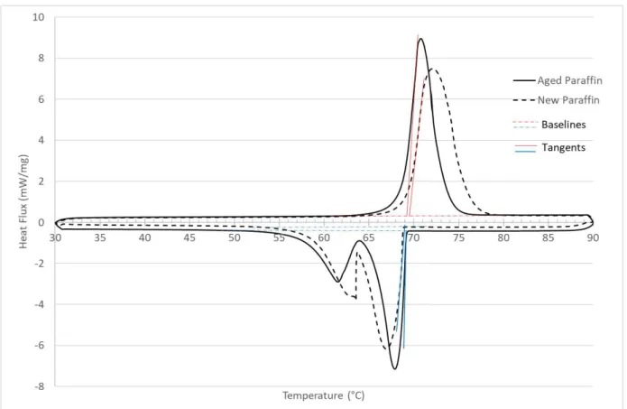
Figure


Documents relatifs
L’archive ouverte pluridisciplinaire HAL, est destinée au dépôt et à la diffusion de documents scientifiques de niveau recherche, publiés ou non, émanant des
L’étude des caractéristiques spermatiques des béliers de race Ouled Djellal nous a montré que : L’effet quantitatif est plus significatif chez les béliers supplémentés,
Keywords: Thermal Energy Storage, Phase Change Material, Convective Heat Transfer
For the enriched sample, the specific value of the thermal conductivity at the peak is different, however the thermal conductivity obtained from theory between 3 K and 10 K and
By treating the Grfineisen constant as a temperature dependent semiadjustable parameter we find that the high temperature lattice thermal conductivity of Ge and Si can be
The reader comes to share the autobiography as a collectively achieved state of being; the autobiography becomes not a history or a philosophical analysis of a
Furthermore, factor analysis of ratings of the most attractive images revealed a factor structure similar that obtained when people rated real office spaces.. Preferred luminances
The principal goal of this project is the correct characterisation of the thermophysical properties of phase change materials (PCMs) in order to have reliable
