HAL Id: hal-00558415
https://hal.archives-ouvertes.fr/hal-00558415
Submitted on 21 Jan 2011
HAL is a multi-disciplinary open access
archive for the deposit and dissemination of
sci-entific research documents, whether they are
pub-lished or not. The documents may come from
teaching and research institutions in France or
abroad, or from public or private research centers.
L’archive ouverte pluridisciplinaire HAL, est
destinée au dépôt et à la diffusion de documents
scientifiques de niveau recherche, publiés ou non,
émanant des établissements d’enseignement et de
recherche français ou étrangers, des laboratoires
publics ou privés.
Microfabricated bistable module for digital
microrobotics.
Qiao Chen, Yassine Haddab, Philippe Lutz
To cite this version:
Qiao Chen, Yassine Haddab, Philippe Lutz. Microfabricated bistable module for digital microrobotics..
Journal of Micro-Nano Mechatronics, Springer, 2011, 6 (1-2), pp.1-12. �10.1007/s12213-010-0025-2�.
�hal-00558415�
Microfabricated Bistable Module For Digital
Microrobotics
Qiao Chen, Yassine Haddab, Philippe Lutz
FEMTO-ST Institute, UMR CNRS 6174-UFC- ENSMM-UTBM,
Automatic Control and Micro-Mechatronic Systems Department24 rue Alain Savary, 25000 Besançon, France
[email protected], [email protected], [email protected]
Abstract— High precision microrobots are needed more and more to perform micro/nanomanipulation and microassembly tasks in various environments like microrobotic stations, electronic microscopes (SEM, TEM), etc. Current microrobots are based on the use of smart materials to perform proportional or incremental actuation. To avoid the main drawbacks of these microrobots (non linearities, integration of sensors, robust control, energy consumption, sensitivity to noise), we propose a new type of microrobots, called digital microrobots, based on microfabricated bistable modules. The study presented in this paper is dedicated to the microfabricated bistable modules, notably the structure and the actuators design and characterization. The results open a new paradigm in the field of microrobotics leading to open loop control and the design of various kinematics adapted to the microworld. Moreover, no external energy is required to maintain the microrobot in its position.
Microrobotics, Bistable mechanism, Thermal actuator, Open-loop control of
robot.
1 INTRODUCTION
During the last decade, significant research activities have been performed in the field of microrobotics. Microrobotics deals with the design, the fabrication and the control of microrobots. These microrobots are intended to perform various tasks in the so-called Microworld (i.e. the world of submillimetric objects), in particular micromanipulation of single objects (artificial or biological) for positioning, characterizing or sorting as well as for industrial microassembly [1]. Research already done has shown that the use of active materials to actuate microrobots gives better performances than the use of traditional actuators. However, despite their intrinsic high resolution, these materials have some drawbacks, making the design of efficient controllers a hard task. Their behavior is often complex, nonlinear and sometimes non stationary (environmental conditions as temperature and humidity have a great influence on static and dynamic behaviors [2]). Closed-loop control of the microrobots requires the integration of very small sensors and the use of bulky and expensive instruments for signal processing and real-time operating. Packaging and integration of sensors and actuators are also hard problems to resolve. This is why building multidegrees of freedom microrobots able to perform complex tasks is difficult [3], [4].
Generally, two actuation modes are used in the control of microrobots to generate movements: the proportional mode and the incremental mode. The proportional actuation is based on the controlled deformation of an active material that directly produces a proportional displacement of the microrobot [5][6]. The use of such a continuous actuation leads to a high cost, the need of a closed-loop control which takes into account the non-linearities [6] and also the use of sensors which are difficult to integrate [8]. The incremental actuation mode is brought into play in the stick-slip [6] and the inchworm systems [9]. The displacement of the microrobot is then discrete. The need of sensors and closed-loop control is still necessary.
In this paper, we propose a new approach for the design and the actuation of microrobots based on the use of bistability. This new concept based on mechanical robustness allows open-loop control of the microrobots, low cost, and no external energy consumption to maintain a position.
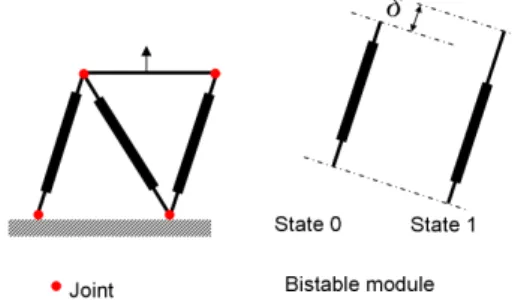
In literature, several conventional robots based on the use of bistable mechanisms are described. However, in the microworld, there is no microrobot based on the bistability concept although bistable structures are widely used. In the macroworld, the most typical discretely-actuated robot is the Variable Geometry Truss (VGT) manipulator (see Fig.1) [10][12]. This planar binary manipulator consists of several modules. Each one includes three binary actuators. As a result, every module has eight states (23).
Fig. 1. A 3-bit binary VGT, "0" or "1" represents one of the states. The δ is the displacement from state 0 to state 1.
G.S. Chirikjian firstly presented the concept of the binary paradigm for robotic manipulators in [13]. There have been several improvements in this binary hyper-redundant manipulator concept. A lot of work about the calculation of the forward and inverse kinematics is done in [14]-[17]. Another robot called Robotic Articulated Intelligent Device (BRAID) is described in [18]; it is a 3-D configuration of binary actuated manipulators. There are 215 states by cascading 5 modules in the 3D workspace. Nevertheless, the VGT and the BRAID present some drawbacks: trajectory following is costly in term of computation because the number of logical state is huge [14], [15] and the inverse kinematics is hard to obtain as indicated in [16][17]. Moreover, the use of joints leads to a repeatability loss due to the joint clearances or gaps. So this kind of structure can not be used as an accurate positioning device. In the microworld, submicrometric resolutions are required. This is why the use of assembled manipulators and joints is avoided. Compliant joints are preferred in order to achieve high performances adapted to the microworld [23], [27]. Miniaturization of the mechanical structure of VGT or BRAID is not suitable.
loop control strategy. The microrobots, named “digital microrobots” are built from several elementary modules. Each one offers a very good repeatability and stable positions. An elementary module gives two stable states. The position of the whole microrobot is controlled by a digital word representing the state of the modules. This opens a new paradigm in the field of microrobotics, allowing the design of various kinematics adapted to the microworld.
The paper is organized as follows: first, the concept of microrobots based on bistable modules is presented. After that, the design of the bistable element is presented, and finally the conclusion and future work are given.
2 General concepts for digital microrobotics
2.1 Bistable module
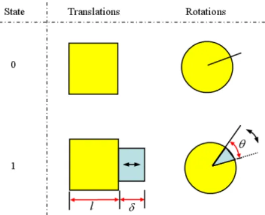
The bistable module is the fundamental element for designing a digital microrobot. The bistable mechanism is a structure or mechanism that has two stable states, Fig. 2 shows the principle of bistable modules.
Fig. 2. Principle of bistable modules, the δ or θ stands for motion between the two stable states. We define state 0 or 1 respectively as one of the two stable states. Between these two stable states there are translations δ or rotation θ. The bistable mechanism is switched from one state to another by applying an external force, and no external energy is needed to maintain the stable states. Many applications of this structure can be found, for example, RF switches, relays, microvalves, etc.
2.2 Robot axis based on bistable modules
A robot axis can be built using several cascaded bistable modules. The number of logical states is thus increased. The final position of the axis is obtained by the accumulation of the discrete displacement (δ) or discrete rotation (θ). The design of each module and consequently their δ or θ defines the characteristics of the reachable workspace. Although only a discrete area can be reached, the number of logical states is an exponent function of the number of bistable modules. A robust mechanical design of the bistable module allows a high positioning resolution to be obtained. In this paper, we only study the case of linear displacements.
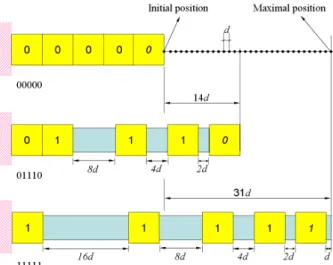
Fig.3 shows an example where 5 modules are used. There are 32 logical states. If the displacements of the modules are defined as: d, 2d, 4d, 8d and 16d (as shown in Fig. 3), where d is the minimum displacement needed, the range of the robot axis is:
(
)
5 1 1 1 1 . 1 2 4 8 16 . 1 . 2 31. 1 1 i i D d d − d = = = = ∑
(1)The minimum displacement d represents the resolution of the axis position.
Fig. 3. The reachable workspace of a robot axis with five cascaded bistable modules.
The position of the tip of the robot axis is represented by a binary word that could be used as a control instruction.
2.3 Discrete reachable workspace and Microrobot applications
The use of bistable modules to design microrobots leads to a discrete reachable workspace. If robust bistable modules with small displacements can be built, a high resolution is obtained and the position of the robot can be controlled in open-loop.
(b)
Fig. 4. (a) Parallel structured microrobot. (b)Serial structured microrobot
Moreover, this approach offers good immunity to noise thanks to the mechanical performances. However, a lot of modules must be built in order to obtain high resolutions. Microfabrication technology is well adapted to the fabrication of monolithic high performance digital microrobots which do not require any assembly process. From discretely actuated axis, robots with various kinematics can be built. Examples are given in Fig. 4.
2.4 Comparison between current microrobots and digital microrobots
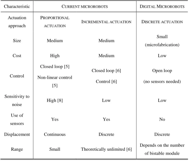
In Table 1, we give a detailed comparison between the characteristics of current microrobots and the proposed digital microrobots.
TABLE 1 A Comparison between current microrobots and digital microrobots
Characteristic CURRENT MICROROBOTS DIGITAL MICROROBOTS Actuation
approach
PROPORTIONAL ACTUATION
INCREMENTAL ACTUATION DISCRETE ACTUATION
Size Medium Medium Small
(microfabrication)
Cost High Medium Low
Control Closed loop [5] Non-linear control [5] Closed loop [6] Control [6] Open loop (no sensors needed)
Sensitivity to
noise High [8] Low Low
Use of
sensors Yes Yes No
Displacement Continuous Discrete Discrete
Range Small Theoretically unlimited [6] Depends on the number of bistable module
The current microrobots are mainly built by assembling the actuators and the mechanical structure. Digital microrobots can be fabricated at low cost in a monolithic manner using microfabrication technology. Moreover, this novel concept has many advantages. Good repeatability and accuracy are obtained thanks to the mechanical performances of the bi-stable modules, that is why neither proprioceptive sensors nor bulky and expensive instruments for signal processing and control are needed. Low power consumption can be obtained because external energy is not needed to maintain the modules in a given state but only during the transition phases. The immunity to noise and to changes of the environment is improved. Using the parallel control of the modules, fast displacements can be obtained. Using bistable structures gives an approach that turns the difficulties of non-linear control into mechanical structure design.
The inchworm or stepper motors can offer also a discrete position. The principle of these motors depends on the friction between the actuator and the contact surface. Each step has an uncertain linked to friction surface. When it goes through the open loops of great number of steps, the final error could be great [4], [6].
Digital microrobots present the advantages discussed before. However, they have some drawbacks: discrete reachable workspace and limited load.
Let us consider an example of a piezoelectric unimorph beam, commonly used in microrobotics, with 14mm length that enables a maximum displacement of 60µ m at its tip under 100V. Taking into account the creep effect, a resolution of 500nm can be reached. According to our proposal, to obtain similar performances, the smallest module must have a displacement of 500nm and 7 cascaded modules are necessary according to equation 1. Microfabrication of such an axis is difficult. Cascading several modules requires that each module carries the weight of the following ones which limits the load.
3 Design of bistable compliant structures
An elastic deformed structure usually goes back to its original shape after unloading the applied force, but some structures go to another position. A structure with the latter behavior is called a bistable structure. This type of structure shows similar characteristics between force and displacement or between elastic deformation energy and displacement. In 2002, M.S. Baker [18] presented on-chip actuation of a compliant bistable mechanism. In which the V-shape thermal actuators were used. In 2004, Jinqiu [21] presented a curved-beam bistable mechanism for designing a relay, in which the actuator and the bistable structure were made in the wafer by micro fabrication. Many bistable structures were fabricated through MEMS technologies [21][23][25]. One of them has been widely studied: the curved-beam bistable mechanism. This compliant mechanism does not need any assembly. Moreover, it can be fabricated by batch processing and it perfectly suits our objective.
To define the dimensions of the bistable mechanism, two factors are considered: the fabrication limits that define the minimal width of the beams of the structure and the size of the thermal actuators required to switch the bistable mechanism. According to the pseudo-rigid-body model
[27], [28], a calculated model is presented in Fig. 5. The bistability is determined by the torsional spring stiffness ks, the elastic beam stiffness kb, and the initial height of the curved beam h.
Fig. 5. An equivalent model for bistable beam
The angle θ of torsional spring and the deformation x of the elastic beam can be expressed as a function of the vertical displacement Y, which is caused by an external force F.
8
.
0
)
)
(
(
2+
2−
2+
−
2×
=
L
h
L
h
Y
x
(2) ) ( tan ) ( tan1 1 L Y h L h − − = − − θ (3) L, h and Y are shown in Fig. 5.The strain energy U can be derived from the torsional spring stiffness ks and the elastic beam stiffness kb: 2 2 2 1 4 2 1 8 ks kb x U= ⋅ ⋅ ⋅θ + ⋅ ⋅ ⋅ (4) Y x x kb Y ks Y U F ∂ ∂ ⋅ × + ∂ ∂ ⋅ ⋅ = ∂ ∂ = 8 θ θ 4 (5) 2 2 2 2 2 2 2 1 1 ) ( ) ( ) ) ( ( 4 ) ) ( 1 ( 1 )) ( tan ) ( (tan 8 Y h L Y h Y h L h L kb L L Y h L Y h L h ks Y U F − − − ⋅ − + − + ⋅ ⋅ + − + ⋅ − − ⋅ ⋅ = ∂ ∂ = − − (6)
Ignoring the high order about Y, The force F can be written as:
L Y h L Y h L Y hY kb L ksY F 4 ) ( 3 ) ( 2 ) 2 ( 4 8 2 2 2 − + − ⋅ − + ≈ (7) The two stable states Ys1 and Ys2 and the unstable state Yu are obtained for F=0.
2 4 2 2 2 4 2 2 2 4 2 2 2 4 2 2 2 1 2 6 16 48 3 6 2 6 16 48 3 6 0 L kb ks ks L kb L ks h L kb h L kb h ks Y L kb ks ks L kb L ks h L kb h L kb h ks Y Y u s s ⋅ ⋅ − ⋅ ⋅ ⋅ ⋅ − ⋅ ⋅ + ⋅ ⋅ − ⋅ ⋅ ⋅ − ⋅ ⋅ = ⋅ ⋅ − ⋅ ⋅ ⋅ ⋅ − ⋅ ⋅ + ⋅ ⋅ + ⋅ ⋅ ⋅ − ⋅ ⋅ = = (8) In our case, ks and kb can be calculated according to the pseudo-rigid-body theory.
L EI ks 1 . 0 = (9) L EA kb 8 . 0 = (10) Where E is the Young’s modulus, I is the inertial moment and A is the section’s area.
According to this model, the required actuation force and displacement stroke can be found. The dimensions adapted to the microfabrication limits in our clean room facility are shown in Fig. 6.
These dimensions are defined by making the trade-off between the fabrication limits and the actuation force. In our case, a force of 3mN has been considered according to the actuators defined in the next section. This choice allows the fabricated bistable mechanism to be actuated using the designed force.
Fig. 6. Curved beams dimensions
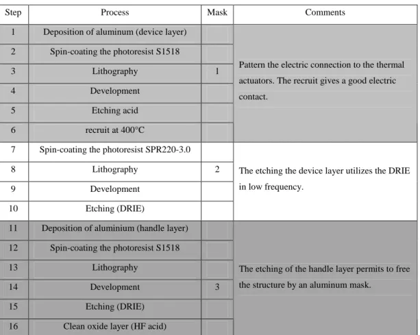
TABLE 2 The process summary to fabricate the bistable module.
This bistable mechanism is fabricated using silicon on insulator (SOI) wafers with 100 m thick device layer, 300 m thick handle and 1 m sacrificial oxide layer. The handle layer is used to support the entire structure, and the bistable structure is fabricated in the device layer.
Firstly, the photoresist is deposited, and then the device layer is etched using DRIE (Deep Reactive Ionic Etching). After that, the aluminum mask is made for the etching of the handle layer. Finally, the oxide layer is etched using hydrofluoric (HF) acid. Since the last step is done in the liquid, some of structures are broken. Table 2 summarizes the fabrication process. The fabricated structure is shown in Fig. 7.
Step Process Mask Comments
1 Deposition of aluminum (device layer) 2 Spin-coating the photoresist S1518
3 Lithography 1
4 Development
5 Etching acid
6 recruit at 400°C
Pattern the electric connection to the thermal actuators. The recruit gives a good electric contact.
7 Spin-coating the photoresist SPR220-3.0
8 Lithography 2
9 Development
10 Etching (DRIE)
The etching the device layer utilizes the DRIE in low frequency.
11 Deposition of aluminium (handle layer) 12 Spin-coating the photoresist S1518
13 Lithography
14 Development 3
15 Etching (DRIE)
16 Clean oxide layer (HF acid)
The etching of the handle layer permits to free the structure by an aluminum mask.
Fig. 7. Microfabricated module
We use the experimental set-up to measure the characteristics of the bistable module. The fabrication result is shown in Fig. 8.
Fig. 8. The experimentation set-up.
A finite element analysis (FEA) is made by using the commercial FEA software ANSYS. The results from the model, the FEA and the static experimentation are presented in Fig. 9.
Fig. 9. Force (F) vs displacement (Y) characteristic. This static experimentation is made by using a commercial force sensing probe (ST-S270 from FEMTO TOOLS [24] with a sensitivity of 899.2µN/V).
This model gives a greater stiffness than the stiffness from FEA because of the simplification of the torsional spring model but it can be considered as a sufficient approximation. Therefore, for switching from a stable state to another one, a microactuator able to produce a force of 2.15mN with a displacement of 65µ m is needed. The next section is dedicated to the design of the actuator.
4 Actuator design
To switch the bistable mechanism, the potential candidates could be piezoelectric, thermal, electrostatic and shape memory alloy (SMA) actuators. Due to the use of the bulk micromachine technology, piezoelectric actuators and SMA actuators are difficult to integrate. The calculation of the electrostatic actuator shows that it takes a lot of space to reach the required force. So we decided to use thermal actuators.
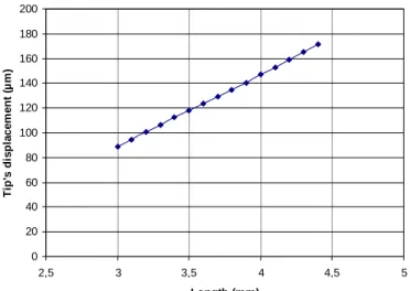
A U-shape thermal actuator has been built from two beams. One beam is called “hot beam” and the other is called “cold beam” [25]. This actuator takes use of the asymmetric deformation to create in-plane displacement. For a given temperature, the tip's displacement magnitude mainly depends on the length of the thermal actuator [25], [26]. Fig. 10 shows the variation of the length Vs tip's displacement at 300oC. We use commercial software ANSYS which offers a structural thermoelectric tetrahedron element (SOLID227) permitting to couple electro-thermal-mechanical analysis. We took into account all the thermal effects: the conduction, the convection, and the radiation (see Fig. 10).
0 20 40 60 80 100 120 140 160 180 200 2,5 3 3,5 4 4,5 5 Length (mm) T ip 's d is p la c e m e n t (µ m )
Fig. 10. Tip's displacement Vs length of actuator without any load.
Like the design of bistable mechanism, the trade-off between the fabrication limits and the switching force needs to be chosen. To fulfill the previous requirement (a force of 2,15mN at 65µm), we chose a length of 4mm. The other dimensions are shown in Fig. 11.
Fig. 11. Designed thermal actuator.
The thermal actuator is fabricated in the device layer of the SOI wafer, in the same way as the bistable mechanism. To obtain a control voltage lower than 24V which is supplied by common voltage generators, we have chosen a wafer with electric resistivity of 0.02 ohm.cm. The pads of the actuator’s supply are electrically insulated from the other parts of the structure in order to avoid short circuits but the handle part is kept for the integration of the whole structure. The contact pads are made of aluminum to ensure a good ohmic contact through the diffusion of Al atoms in the silicon. Fig. 12 shows two microfabricated thermal actuators.
Fig. 12. Two microfabricated thermal actuators.
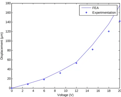
0 2 4 6 8 10 12 14 16 18 20 0 20 40 60 80 100 120 140 160 180 Voltage (V) D is p la c e m e n t (µ m ) FEA Experimentation
Fig. 13. The static behavior of the thermal actuator.
Fig. 14 shows the response of the actuator to a square input voltage with 8 volts amplitude. The settling time is about 0.37s for a rising edge and 1.38s for a falling edge. The difference is due to the dissipation of the heat in the silicon. The characteristics required to switch the bistable structure are obtained with this actuator. Indeed, at a displacement of 140µm without any load (which is equivalent to a force of 2.2 mN at a displacement of 65µm) is obtained under a driving voltage of 20V.
Fig. 14. Dynamic response of the thermal actuator.
According to [29][30], the thermal convection and radiation can be neglected in the microworld, so the heat is accumulated in the structure. Energy of 12mJ is needed for every switching operation. This energy is quickly transferred to the substrate thanks to the good thermal conductivity of the silicon. Two pairs of thermal actuators are used to switch the bistable structure. This energy is needed only for switching. Since the positions are given by the stop blocks, no energy is required for maintaining these positions.
5 Stop block design
In order to ensure the bistability and a blocking force to the bistable structure in each state, we need to limit the displacement of the structure before it reaches its maximum position. The use of two stop blocks is thus necessary. The previous realizations [21],[28] of bistable mechanism can not meet this requirement. This bistable mechanism has to move between the blocked positions in order to produce a blocking force for each of the two positions. It is difficult to obtain naturally two pre-stressed positions with a high blocking force because of the monolithic microfabrication. To solve this problem, we designed dedicated compliant mechanisms. The first stop block is a compliant mechanism (see Fig. 15). The beam deforms under an external activation force, and finally is forced into the stop block.
(a)
(b)
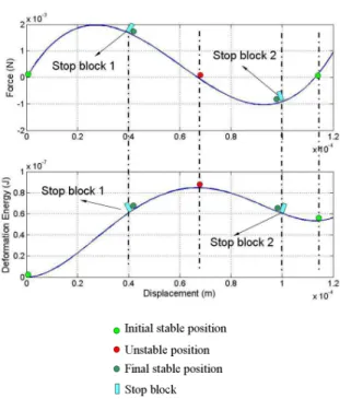
Fig. 15. (a) The stop block after microfabrication, (b) the stop block after insertion of the shuttle The second one is located at the other side of the unstable position (see Fig. 16). The distance between these two stable positions can be chosen according to the design and the targeted displacement of the module. The position of the two stop blocks defines the displacement of the module and the blocking forces (the maximum forces that can be applied to the shuttle without losing the contact between the shuttle and the stop blocks).
Due to the monolithic microfabrication of the overall module, a first activation is necessary in order to insert the shuttle between the two stop blocks. The first activation gives a pre-energy in the structure which allows reducing the actuation energy to switch the bistable structure.
Fig. 16. The locations of the stop blocks in the force/displacement and energy/displacement characteristics.
Fig. 17. One bistable module: four thermal actuators, two bistable beams, stop blocks, and a frame. The whole bistable module which contains two bistable beams, four thermal actuators, a frame and a shuttle is finished (see Fig. 17). Compared to the previous works on bistable structures, our design allows getting a blocked force in two positions.
Fig. 18 The experimental set-up.
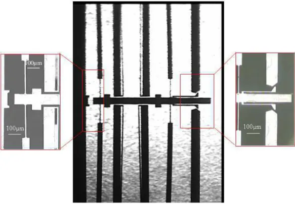
In this test, the bistable modules are prepared for an in-plane measurement. For this measurement, we use a high resolution (10 nm) interferometer from SIOS Technology to measure the displacement of the bistable mechanism. All the test devices are mounted on an antivibration table (see Fig .18).
Fig. 19 shows photos of the stop blocks during operation.
Fig. 19. (a1) The position just after fabrication (a2) The activated position (b1) The activated position (b2) The switched position.
In the module shown in Fig. 18, the measured displacement of the shuttle is 10.1µ m. The stop blocks give 1.54mN blockage force to limit the displacement of the shuttle.
6 Overall designs
Because the overall structure is composed of a large number of similar bistable modules, it is very important to consider the relationship between the overall structure and the bistable module. Firstly, two cascaded bistable modules are considered (see Fig. 20). Since the two curved-beams will support all the structure weight in the first bistable module, it is necessary to study the gravity effect in the structure.
In order to find the out-of plan stiffness caused by gravity, we performed a calculation model presented in Fig. 21.
Fig. 21. The equivalent out-of plane model of bistable module.
In this calculation model, the two bistable curved beams are considered as two springs, and the actuators and the frame are considered as a rigid beam. Only the spring causes a flexion. The gravity center of every bistable module is located in the middle of the two springs.
For n bistable modules, we simplify the model as in Fig. 22. The total moment MT= (M (n 2
-n)/2+MG) and total force FT= (nF+G) are the equivalent moment and force of the n bistable
modules which are applied on the first bistable module. The out of plane flexion can be obtained:
k L L L L L n L G L L n n F k G nF L L k L M k FT T n 2 1 1 1 2 1 2 5 . 0 ) ( ) 2 )) )( 1 ( 5 . 0 ( 2 ) )( ( ( ) ( 5 . 0 + + − + + + − + + = + + =
δ
(11)Fig. 22. Model of n cascaded bistable modules. The total displacement can be obtained:
∑
∑
= =+
+
−
+
+
+
−
+
+
=
+
+
=
n n n n T T Tk
L
L
L
L
L
n
L
G
L
L
n
n
F
k
G
nF
L
L
k
L
M
k
F
1 2 1 1 1 2 1 1 25
.
0
)
(
)
2
))
)(
1
(
5
.
0
(
2
)
)(
(
(
)
(
5
.
0
δ
(12)The spring is a variable section cantilever beam, of which stiffness k can be determined by a classic cantilever model:
3 2 3 2 3 3 3 38 10 8 . 0 1 . 0 8 . 0 2 1 . 0 9 . 0 3 1 . 0 1 . 0 1 2 l EI l EI k = × + + × + + × × = (13)
Where E is the Young’s modulus, I is the inertial moment and l is the length of cantilever beam. Each bistable module has a mass of 2.128mg. We simulate the deflection of cascaded structures carrying at the tip a silicon sphere with a diameter of 300µm (mass: 0.0325mg). The comparison of the tip's flexion between the model and the FEA is presented in table 3 for cascaded bistable modules with 1 to 4 modules.
TABLE 3 tip's flexion comparison between the model and the FEA
n Model (µm) FEA (µm)
1 0.24 0.22
2 2.11 1.9.1
3 16.8 14.4
4 41.6 38.2
The tip's flexion is accumulated with the increase of the bistable modules. The analysis shows that there isn't much stress in the first bistable module. Nevertheless, the tip of the structure has an important flexion. According to the equations 12 and 13, we can obtain:
∝
∝
∝
31
1
1
h
I
k
nδ
(14) According to the equation 14, the tip's flexion could be reduced with the increase of the thickness of the structure. In our case, the tip’s flexion is 2µ m with a thickness of 100µ m.This flexion is neglected.7 Conclusion and future work
In this paper, we have presented a new concept for microrobotics: the digital microrobot. More precisely, we have designed the elementary component of this kind of microrobot: the microfabricated bistable module. This module is fabricated in a monolithic manner on a SOI wafer.
We have described and characterised each part of this module: the bistable compliant structures, the thermal actuators and the stop blocks which enable to give robust positions and blockage forces. The batch microfabrication permits to fabricate monolithic structures containing several modules without any assembly. For example, a microrobot axis is built by cascading several bistable modules to reach a discrete workspace.
This digital microrobot takes advantage of bistable mechanism, such as repeatability and reliability. The proposed design of bistable module allows getting two stables positions with a blocking force useful for micromanipulation operations.
The study shown in this paper opens the possibility to cascade several modules to get robust positions in a discrete workspace. The main advantages of the digital microbotics approach are: repeatability and robustness obtained with mechanically blocked positions, and ease of control because of the open loop condition. Moreover, because each module can be triggered independently, parallel control allows reducing the time to get a position.
Future work will include the dynamic characterization of the dynamic of bistable mechanism, and the fabrication of several cascaded bistable modules.
Acknowledgment
The fabrication of the bistable modules has been realized in the clean room of Femto-st institute. The authors would like to thank the engineers of the clean room and Joel Agnus for sharing the microfabrication know-how.
References
[1] B. Lopez-Walle, M. Gauthier and N. Chaillet, "Principle of a submerged freeze gripper for microassembly," IEEE Trans. Robotics, vol.24, no.4, pp.897-902, Aug. 2008.
[2] M. Rakotondrabe, C. Clévy and P. Lutz, 'Hysteresis and vibration compensation in a nonlinear unimorph piezocantilever', IEEE/RSJ - IROS, (International Conference on Intelligent Robots and Systems), pp:558-563, Nice France, Sept 2008.
[3] H. Bamberger and M. Shoham "A novel six degrees-of-freedom parallel Robot for MEMS fabrication," IEEE Trans. Robotics, vol.23, no.2, pp.189-195, Apr. 2007.
[4] M. Rakotondrabe, Y. Haddab and P. Lutz, “Development, modelling and control of micro/nano positionning 2 dof stick-slip device”, IEEE/ASME Trans. Mechatronics, to appear in 2009 (VOL.14), doi: 10.1109/TMECH.2008.2011134.
[5] M. Rakotondrabe, Y. Haddab and P. Lutz, “Quadrilateral modelling and robust control of a nonlinear piezoelectric cantilever”, IEEE Trans. Control Syst. Technol, Vol.17, to appear in 2009.
[6] M. Rakotondrabe, Y. Haddab and P. Lutz, 'Voltage/frequency proportional control of stick-slip microsystems', IEEE Trans. Control Syst. Technol (T-CST), Vol.16, Issue 6, pp:1316-1322, Nov. 2008.
[7] S. Devasia, E. E. Eleftheriou and R. Moheimani, ‘A survey of control issues in nanopositioning’ IEEE Trans. Control Syst. Technol, Vol.15, No15, pp.802-823, 2007. [8] Y. Haddab, Q. Chen and P. Lutz, “Improvement of strain gauges micro-forces measurement
using Kalman optimal filtering”, Int. J. IFAC Mechatronics, Vol. 19, Number 4, 2009, doi:10.1016/j.mechatronics.2008.11.012.
[10] H. Robertshaw and C. Reinholtz, "Variable geometry tresses." in Smart Mate. Struc. Math.
Issues.1988, pp.105-120.
[11] K. Miura and H. Furaya, "Variable geometry truss and its applications to deployable truss and space crane arm." Acta Astro. 1985, 12(7): pp. 599-607.
[12] P. Hughes, P. Sincarsin and K. Carroll, "Truss arm a variable-geometry Trusses." in J. Intell.
Mat. Syst. and Stru.. 1991, l.2: pp.148-160.
[13] G. S. Chirikjian, "A binary paradigm for robotic manipulators" in Proc. 1994 IEEE Conf.
Robot. Autom pp. 3063-3070.
[14] D. Lees and G. S. Chirikjian, "A combinatorial approach to trajectory planning for binary manipulators." in Proc. 1996 IEEE Int. Conf. Robot. Autom. pp. 2749-2754.
[15] D. Lees and G. S. Chirikjian, "An efficient method for computing the forward kinematics of binary manipulators." in Proc. 1996 IEEE Int. Conf. Robot. Autom., 1012-1017.
[16] D. Lees and G. S. Chirikjian, "Inverse kinematics of binary manipulators with applications to service robotics." in Proc. 1996 IEEE Int. Conf. Robot. Autom. pp. 2749-2754.
[17] I. E. Uphoff and G. S Chirikjian, "Inverse kinematics of discretely actuated hyper-redundant manipulators using workspace densities." in 1996 IEEE Int. Conf. Robot. Autom. pp. 1: 139 – 145.
[18] V. A. Sujan, "Design of a lightweight hyper-redundant deployable binary manipulator", in J.
Mech. Design, 2004, Vol. 126(1), pp.29-39.
[19] R.Y. Robert, "Mechanical digital-to-analog converters", in Proc.int. conf. on solid-state
sensors and actuators. Transd.'99, Jun. 1999, sendai, japan, pp.998-1001.
[20] M. S. Baker, "On-chip actuation of compliant bistable micro-mechanisms," in M.S. Thesis, Brigham Young University, Provo, Utah.
[21] J. Qiu, “A curved-beam bistable mechanism,” in J. MicroElectroMechanical Syst., Apr.2004.vol. 13- 2, pp. 137-146.
[22] T. Jinni, "Design and experiments of fully compliant bistable micromechanisms" in Mech.
Mach. Theory, 40 (2005), pp. 17–31.
[23] T. Gomm, "Development of in-plane compliant bistable microrelays," in M.S. Thesis, Brigham Young University, Provo, Utah.
[24] FEMTO TOOLS, FT-S Force Sensing Probes [On line]. Available: http://www.femtotools.com/index.php?page=2&sub=21
[25] Y. Dong, "Mechanical design and modeling of MEMS thermal actuators for RF applications", in M.S.thesis, University of Waterloo, 2002.
[26] R. Cragun, "Thermal microactuators for microelectromechancial Syst. (Mems)", in M.S. Thesis, Brigham Young University, Provo, Utah.
[27] L. L. Howell, book, "Compliant mechanisms". John Wiley & Sons Limited, 2001. ISBN: 0-471-38478-X.
[28] H. hwang, "Modeling and experimental characterization of the chevron-type bistable microactuator", in J. micromechanics and microengineering, 13(2003),pp. 948-954.
[29] N. Mankame, "The effect of thermal boundary conditions and scaling on Electro-thermal-compliant micro devices", in Tech. Proc. of the 2000 Int. Conf. Modeling and Simulation of
Microsystems, pp.609 – 612.
[30] Q. Huang and N. Lee, "Analysis and design of polysilicon thermal flexure actuator," in J.
Micromech.Microeng, 9, 98, pp. 64-70.
Fig. 1. A 3-bit binary VGT, "0" or "1" represents one of the states. The δ is the displacement from state 0 to state 1.
Fig. 2. Principle of bistable modules, the δ or θ stands for motion between the two stable states. Fig. 3. The reachable workspace of a robot axis with five cascaded bistable modules.
Fig. 4. (a) Parallel structured microrobot. (b)Serial structured microrobot Fig. 5. An equivalent model for bistable beam
Fig. 6. Curved beams dimensions Fig.7. Microfabricated module Fig. 8. The experimentation set-up.
Fig. 9. Force (F) vs displacement (Y) characteristic. This static experimentation is made by using a commercial force sensing probe (ST-S270 from FEMTO TOOLS [23] with a sensitivity of 899.2µN/V)
Fig. 10. Tip's displacement Vs length of actuator. Fig. 11. Designed thermal actuator.
Fig. 12. Two microfabricated thermal actuators. Fig. 13. The static behavior of the thermal actuator.
Fig. 14. Dynamic response of the thermal actuator. The settling time is about 0.37s for a rising edge and 1.38s for a falling edge. The difference is due to the dissipation of the heat in the silicon. Fig. 15. (a) The stop block after microfabrication, (b) the stop block after insertion of the shuttle Fig. 16. The locations of the stop blocks in the force/displacement and energy/displacement characteristics.
Fig. 17. One bistable module: four thermal actuators, two bistable beams, stop blocks, and a frame. Fig. 18. The experimental set-up.
Fig.19. (a1) The position just after fabrication (a2) The activated position (b1)The activated position (b2) The switched position.
Fig.22. Model of n cascaded bistable modules.
TABLE 1 A Comparison between current microrobots and digital microrobots TABLE 2 The process summary to fabricate the bistable module.
![Fig. 9. Force (F) vs displacement (Y) characteristic. This static experimentation is made by using a commercial force sensing probe (ST-S270 from FEMTO TOOLS [24] with a sensitivity of 899.2µN/V)](https://thumb-eu.123doks.com/thumbv2/123doknet/8010556.268463/11.892.328.642.115.382/force-displacement-characteristic-static-experimentation-commercial-sensing-sensitivity.webp)