HAL Id: tel-01104791
https://hal.archives-ouvertes.fr/tel-01104791
Submitted on 19 Jan 2015HAL is a multi-disciplinary open access
archive for the deposit and dissemination of sci-entific research documents, whether they are pub-lished or not. The documents may come from teaching and research institutions in France or abroad, or from public or private research centers.
L’archive ouverte pluridisciplinaire HAL, est destinée au dépôt et à la diffusion de documents scientifiques de niveau recherche, publiés ou non, émanant des établissements d’enseignement et de recherche français ou étrangers, des laboratoires publics ou privés.
System on Chip architectures
Romain Brillu
To cite this version:
Romain Brillu. Efficient design and programming of Multiple Processors System on Chip architectures. Engineering Sciences [physics]. UNIVERSITE DE NANTES, 2014. English. �tel-01104791�
Thèse de Doctorat
Mémoire présenté en vue de l’obtention
du grade de Docteur de l’Université de Nantes Sous le label de l’Université Nantes Angers Le Mans Discipline : Electronique
Spécialité : Systèmes Embarqués Laboratoire : IETR UMR 6164
Soutenue le 12 novembre 2014
École doctorale Sciences et Technologies de l’Information et Mathématiques (STIM)
JURY
Président M. Alain DARTE, CNRS Research Director, Laboratoire de l’Informatique du Parallélisme, Lyon
Rapporteur M. Frédéric PÉTROT, Professor, École Nationale Supérieure d’Informatique et de Mathématiques Appliquées de Grenoble Rapporteur M. Gilles SASSATELLI, CNRS Research Director, Laboratoire d’Informatique de Robotique et de Microélectronique de Montpellier Examinateur M. Jürgen TEICH, Professor, Friedrich-Alexander-Universität Erlangen-Nürnberg, Deutschland
Directeur de Thèse M. Sébastien PILLEMENT, Professor, École polytechnique de l’université de Nantes Co-Directeur M. Fabrice LEMONNIER, Research Engineer/HDR, Thales Research & Technology, Palaiseau Encadrant M. Philippe MILLET, Research Engineer, Thales Research & Technology, Palaiseau
Travaux réalisés dans le cadre d’une CIFRE avec Thales Research & Technology (Palaiseau)
ED STIM 503
Romain BRILLU
Efficient design and programming of Multiple Processors System
on Chip architectures
`
Remerciements
Ah les remerciements, derni`ere ´etape dans la r´edaction de cette th`ese qui peut paraˆıtre simple mais qui n’en est rien, bien au contraire car r´esumer en quelques lignes tout ce que vous m’avez apport´e au cours de ces trois ann´ees est difficile et le plus dur pour moi reste l’impair d’oublier quelqu’un. Si tel est le cas que ces personnes me pardonnent.
Je souhaite avant tout remercier l’ensemble des membres de mon jury, Monsieur Alain Darte pour avoir accept´e d’en ˆetre le pr´esident, Messieurs Fr´ed´eric P´etrot et Gilles Sassatelli pour avoir accept´e d’en ˆetre les rapporteurs et Monsieur J¨urgen Teich pour avoir accept´e d’en ˆetre l’examinateur.
Ensuite comment ne pas citer mon directeur de th`ese S´ebastien Pillement sans qui cette th`ese n’aurait pas ´et´e `a son terme. Merci pour le soutien, la confiance apport´ee et pour m’avoir aid´e `a d´evelopper et `a formaliser mes id´ees afin que je puisse mener `a bien cette th`ese. Comme tu me l’a si bien dit au d´ebut de cette aventure ”La recherche est avant tout un ´echange” et ce fˆut un v´eritable plaisir d’´echanger avec toi tout au long de ces trois ann´ees aussi bien professionnellement que personnellement.
Je remercie ´egalement mon co-directeur de th`ese Fabrice Lemonnier pour m’avoir permis de faire cette th`ese et m’avoir accord´e une grande confiance et libert´e dans le d´eveloppement et la r´ealisation de cette derni`ere.
Un clin d’oeil `a Fr´ed´eric Falzon pour notre collaboration et `a mon encadrant Philippe Millet pour les conseils apport´es au cours de ce doctorat.
Merci au Spearou, Michel, R´emi, Paul et Teodora pour leur sympathie, la patience, le temps qu’ils m’ont accord´es et pour avoir ´et´e pr´esents pour moi d`es que j’avais un probl`eme ou des questions.
Ces remerciements ne seraient pas complets si je ne remercie pas ici Christophe pour l’ensemble des connaissances qu’il m’a transmises, le temps et la confiance qu’il m’a accord´e et pour la patience qu’il a eu mon ´egard. Sache que venir `a Thales sans nos ´echanges forts po´etiques que ce soit dans les transports ou au bureau n’avaient plus la mˆeme saveur.
Au rayon des po`etes comment ne pas penser `a Lionel pour sa gentillesse, sa disponibilit´e, sa bonne humeur et son sens inn´e de la d´edramatisation. Merci pour l’aide que tu a pu m’apporter aux diff´erentes ´etapes de cette th`ese et pour les moments partag´es.
Je remercie aussi Hai le Zidane vietnamien pour cette ann´ee commune pass´ee `a Lannion, pour ces parties de baby-foot engag´ees (Mais tu es quand mˆeme particuli`erement mauvais) et pour tous les fou rires que nous avons eu. Au plaisir de te revoir dans la magnifique capitale de la Bretagne qu’est Rennes. Cette derni`ere phrase est particuli`erement destin´ee aux Nantais, je pr´ef`ere pr´eciser au cas o`u ils n’auraient pas compris ce qui n’aurait rien d’´etonnant.
Vu qu’on parle des Nantais je remercie l’ensemble des membres de l’IETR Nantes. J’ouvre n´eanmoins ici un apart´e destin´e aux Nantais r´ecalcitrant `a voir la v´erit´e en face (Ils se reconnaˆıtront) pour leur sig-naler que le R de IETR signifie Rennes. Ce qui d´emontre ce qui ne devrait plus ˆetre `a d´emontrer la sup´eriorit´e manifeste de la capitale Bretonne sur sa voisine Franc¸aise et leur incoh´erence `a vivement critiquer cette magnifique ville et ses clubs sportifs.
Maintenant que ce point `a ´et´e clarifi´e je remercie particuli`erement au sein de l’IETR la team caf´e pour l’ensemble des bons moments partag´es et des conseils plus ou moins pertinents distill´es si et l`a. Distinction particuli`ere `a Lo¨ıc et Yann pour leurs recettes culinaires. En effet la recette du gˆateau cram´e sur le dessus et pas cuit au centre et la recette du gˆateau cuit que sur les extr´emit´es m’´etaient inconnu avant leur rencontre.
Je remercie aussi tous les membres de la team billard pour m’avoir permis de croire que j’´etais bon `a ce jeu. Merci particulier `a Guillaume pour cette victoire ´ecrasante que nous avons connu au tournoi.
Merci `a la team football pour l’ensemble des matchs disput´es mˆeme si cela m’a valu quelques cour-batures et une blessure `a une cuisse. Les matchs Chine contre le reste du monde vont me manquer.
Je remercie aussi le Justin Bieber indien Chagun pour ces trois ann´ees de th`ese partag´ees. Merci pour ta zenitude (qui peut quand mˆeme ˆetre stressante par moment), ta bonne humeur et ta joie de vivre. Je te remercie moins pour m’avoir arrach´e quelques larmes en me faisant d´ecouvrir la cuisine indienne.
Un grand merci a Jo¨elle et Sandrine pour leur bonne humeur et disponibilit´e, vous m’avez simplifi´e la vie et permis de me concentrer pleinement sur mes travaux.
Afin de n’oublier personne je remercie Philippe Bonnot, Olivier Sentieys, Jean-Franc¸ois Diouris et l’ensemble de leurs ´equipes pour m’avoir accueilli au sein du laboratoire des syst`emes embarqu´es de Thales Research & Technology, du laboratoire de l’IRISA de Lannion et du laboratoire de l’IETR de Nantes.
En tant que fervent supporter du plus grand club de l’ouest je ne peux que remercier le Stade Rennais FC pour la sublime d´efaite inflig´ee aux Nantais le dimanche 23 f´evrier 2014 qui m’a apport´e courage et inspiration dans la phase de r´edaction. J’ai une attention particuli`ere pour Ola, Anders et Paul-Georges et leurs trois magnifiques buts plant´es en ce beau dimanche apr`es-midi.
Comme le dit si bien le dicton il faut garder les meilleurs pour la fin et donc ma famille pour avoir ´et´e toujours derri`ere moi.
Merci `a ma mamie Marie pour s’etre occup´e de moi lors de mes jeunes ann´ees.
Je remercie challeureusement ma mamie ´Emile pour avoir veill´e sur moi depuis que je suis tout petit et pour m’avoir soutenue jusqu’au bout dans cette th`ese alors que ta sant´e ne te le permettait pas. Je te confirme aussi que j’avais bien besoin d’un doctorat pour faire les fameux ”roul´e boul´e”.
Merci `a ma filleule et ni`ece Ga¨ella pour avoir su me d´etendre et me faire rire que ce soit par des tours en LEGO, des dessins, des sorties en v´elo, des balades aux parc ou des chants.
Merci `a mes soeurs H´el`ene et ´Elise pour m’avoir permis chacune `a leur mani`ere d’en ˆetre l`a au-jourd’hui, pour tous les souvenirs et moments partag´ees et pour avoir toujours ´et´e `a mes cot´es que ce soit dans les bons ou les mauvais moments.
Un grand merci `a ma femme Aur´elie pour avoir faire preuve d’une grande patience `a mon ´egard, su me soutenir dans les moments difficiles, m’avoir remont´e le moral, fait rire et avoir fait en sorte que je garde le sourire tout au long de cette th`ese.
J’adresse une tr`es grande reconnaissance et un tr`es grand merci a mes parents Michel et Paulette. ´
Enum´erer la liste de tout ce vous avez fait pour moi en quelques lignes est impossible donc merci pour tout. Si j’en suis l`a aujourd’hui c’est avant tout grˆace `a vous et ce doctorat est aussi le votre.
Pour finir je remercie avec ´emotion ”le grand” `a qui j’avais promis avant qu’il nous quitte de mener `a bien ce doctorat et dont la m´emoire m’a permis de surmonter bien des difficult´es aux cours de ces trois ann´ees.
Contents
R´esum´e en franc¸ais i
Contexte et motivations . . . i
1 Introduction 1 1.1 Context and motivations . . . 2
1.1.1 Problem statement . . . 2
1.1.2 Contributions . . . 9
1.2 Manuscript organization . . . 10
2 State of the art 11 2.1 Introduction . . . 12
2.2 MPSoC architectures . . . 12
2.2.1 Introduction. . . 12
2.2.2 Single task processor . . . 13
2.2.2.1 Symmetric multiprocessors . . . 13
2.2.2.2 Asymmetric multiprocessors . . . 18
2.2.3 Multiple tasks processor . . . 21
2.2.4 Summary . . . 23
2.3 Design space exploration tool flow . . . 25
2.3.1 Introduction. . . 25
2.3.2 System level framework . . . 26
2.3.3 Micro-architectural framework. . . 30
2.3.4 HLS framework. . . 33
2.3.5 Summary . . . 35
2.4 Summary . . . 36
3 Parsimonious architecture solution space exploration 37 3.1 Introduction . . . 38 3.2 Definitions. . . 38 3.2.1 Application model . . . 38 3.2.2 Task model . . . 39 3.2.3 Architecture model . . . 40 3.2.4 Nomenclature. . . 41 3.3 DSE methodology. . . 42 3.3.1 Presentation. . . 42 3.3.2 Methodology description . . . 44
3.3.2.1 DSE methodology inputs . . . 44
3.3.2.2 Code parallelization . . . 45
3.3.2.3 Profiler . . . 46
3.3.2.4 Parsimonious representation. . . 46
3.3.2.5 PARSE . . . 47
3.3.2.6 SystemC simulation . . . 49
3.3.2.7 Binary and HDL code generation . . . 49
3.4 Mapping exploration . . . 50 3.4.1 Introduction. . . 50 3.4.2 Tabu search . . . 51 3.4.2.1 Presentation . . . 51 3.4.2.2 Neighborhood generation . . . 52 3.4.2.3 Diversification operator . . . 53 3.4.2.4 Metrics . . . 53 3.4.2.5 Analytic performance . . . 55 3.4.2.6 Cost function . . . 56 3.4.3 Experimental results . . . 57 3.4.3.1 Experimentations parameters . . . 58 3.4.4 Results . . . 59 3.4.4.1 Communication cost. . . 59 3.4.4.2 Exploration runtime . . . 63
3.5 Data placement exploration . . . 64
3.5.1 Introduction. . . 64
3.5.2 Genetic algorithm with fusion operator . . . 65
3.5.2.1 Presentation . . . 65 3.5.2.2 Chromosome encoding . . . 66 3.5.2.3 Fusion operator . . . 67 3.5.3 Experimentation . . . 68 3.5.3.1 Experimentations parameters . . . 69 3.5.4 Results . . . 70
3.5.4.1 Memory and communication cost . . . 70
3.5.4.2 Fusion operator cost . . . 71
3.5.4.3 Exploration runtime . . . 72
3.6 TSRS-GAFO . . . 73
3.6.1 Experimentation . . . 73
3.6.1.1 Architecture models . . . 73
3.6.1.2 Algorithm Parameters settings . . . 75
3.6.2 Results . . . 75
3.6.2.1 Memory and communication cost . . . 75
3.6.2.2 Exploration runtime . . . 76
3.6.2.3 Influence of the
α
parameters. . . 773.7 Summary . . . 79
4 Globally homogeneous architecture but locally heterogeneous cores 81 4.1 Introduction . . . 82
4.2 FlexTiles . . . 82
4.2.1 FlexTiles Platform . . . 83
CONTENTS 11 4.2.3 Reconfigurable layer . . . 84 4.2.4 NoC . . . 85 4.2.5 Programming model . . . 85 4.2.6 Software tools . . . 86 4.3 Accelerator interface . . . 87 4.3.1 Introduction. . . 87 4.3.2 Architecture. . . 88 4.3.2.1 Arbitrator . . . 88 4.3.2.2 Control/Status channel. . . 89 4.3.2.3 Programming channel . . . 89
4.3.2.4 Data Input and Output channel . . . 90
4.3.3 Command interface . . . 90
4.3.4 Synchronization scheme and execution patterns . . . 91
4.3.5 Experimentation and results . . . 93
4.3.5.1 FlexTiles Board . . . 93
4.3.5.2 Application . . . 93
4.3.5.3 FlexTiles platform Implementation . . . 94
4.3.5.4 Impact of the accelerator interface . . . 95
4.3.5.5 Mapping test . . . 96
4.4 Cluster based architecture a memory abstraction . . . 98
4.4.1 Introduction. . . 98 4.4.2 System description . . . 99 4.4.2.1 Architecture presentation . . . 99 4.4.2.2 Cluster Architecture . . . 100 4.4.3 Memory node . . . 101 4.4.3.1 Partition Table . . . 101
4.4.3.2 Address Generation Uuit . . . 102
4.4.3.3 Memory Protection Unit. . . 102
4.4.4 Operating Principle . . . 103
4.4.4.1 Intra cluster communication . . . 103
4.4.5 Inter cluster communication . . . 105
4.4.6 Experimentation and results . . . 105
4.4.6.1 Simulation environment . . . 105
4.4.6.2 Application . . . 109
4.4.6.3 Influence of the data placement and task mapping . . . 113
4.4.7 Hardware Implementation . . . 114
4.5 Summary . . . 115
5 Conclusions and perspectives 117 5.1 Conclusions . . . 118 5.2 Perspectives . . . 121 5.2.1 Mid-term perspectives . . . 121 5.2.2 Long-term perspectives. . . 122 Personal Publication 125 Abbreviations 127
A Annex A 131
A.1 Methodology implementation. . . 132
A.1.1 Library of architecture . . . 132
A.1.2 Code parallelization . . . 132
A.1.3 Profiler . . . 132
A.1.4 SystemC simulation and Binary code generation . . . 132
A.1.4.1 HDL code generation . . . 133
A.2 Justification of the Tabu search Parameters . . . 134
A.2.1 Justification of the tabu search memory size and of the number of iteration . . . 134
A.2.2 Justification of the tabu search diversification operator level . . . 135
A.3 Application benchmarks . . . 136
A.4 Benchmarks architecture model . . . 137
A.5 Justification of the Genetic algorithm parameters . . . 138
A.5.1 Justification of the population size . . . 138
A.5.2 Justification of the number of generation. . . 138
A.5.3 Justification of the crossover rate. . . 139
A.5.4 Justification of the mutation rate . . . 140
A.5.5 Justification of the FO rate . . . 140
A.6 Application task graph . . . 142
A.7 Data placement representation . . . 144
A.7.1 Example of data placement obtained for the chirp application. . . 144
A.7.2 Example of data placement obtained for the jpeg application . . . 144
A.7.3 Example of data placement obtained for the stap application . . . 146
A.8 TSRS-GAFO . . . 148
A.8.1 Chirp . . . 148
A.8.1.1 Mapping . . . 148
A.8.1.2 Data placement . . . 148
A.8.2 Jpeg . . . 148
A.8.2.1 Mapping . . . 148
A.8.2.2 Data placement . . . 149
A.8.3 Stap . . . 151
A.8.3.1 Mapping . . . 151
A.8.3.2 Data placement . . . 151
B Annex B 153 B.1 Accelerator Interface . . . 154
B.1.1 Vehicle registration plate detection synchronization scheme and execution pat-terns . . . 154
B.2 Cluster based architecture a memory abstraction . . . 159
B.2.1 2D-FFT application mapping . . . 159
B.2.2 Cluster based architecture mapping . . . 159
B.2.3 Flat architecture mapping . . . 160
B.2.4 Ter@ops architecture mapping . . . 161
B.2.5 Matrix multiplication application mapping . . . 162
B.2.6 Cluster based architecture mapping . . . 162
B.2.7 Flat architecture mapping . . . 163
CONTENTS 13
List of Figures
1.1 The graph shows the computational requirements of different application grouped by
application domains [107]. . . 2
1.2 Typical MPSoC architecture based on several GPP connected through an interconnect (Bus or Noc based) along with a DDR memory and all the peripherals needed for a connection with the outside environment. These MPSoC is homogeneous and can target several kinds of computation. . . 3
1.3 Evolution of the memory performance in regards of the processor performance [111]. . . 4
1.4 Point to point interconnection network . . . 5
1.5 Bus interconnection network . . . 6
1.6 Representation of a NoC . . . 6
1.7 Typical heterogeneous MPSoC architecture. . . 8
2.1 Non-exhaustive list of the evolution of the multiple cores architectures in regards of their number of cores and their year of production [107]. . . 12
2.2 Classification of the MPSoC architectures [74]. . . 13
2.3 Example of task mapping on a SMP MPSoC. . . 14
2.4 Representation of a MPSoC architecture with a shared L2 cache . . . 15
2.5 The clustered TSAR architecture using shared memory . . . 16
2.6 Architecture of a TileGX tile organized around a GPP, a cache memory, a cache coher-ence mechanism, peripherals for synchronization and data transfers and a NI for network connection. . . 17
2.7 Architecture of a SCC tile organized around two GPP along with their cache memory, peripherals for synchronization and data transfers, a LMB and a MIU. . . 17
2.8 Logical representation of a asymmetric architecture.. . . 18
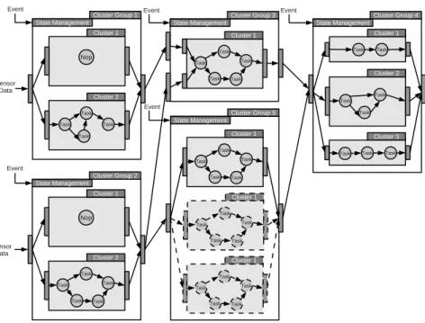
2.9 (A) Overview of the MPPA 256 architecture. (B) Architecture of a MPPA cluster. . . 19
2.10 The SCMP architecture.. . . 19
2.11 (A) Representation of the STHORM architecture. (B) Architecture of a STHORM cluster. 21 2.12 Logical representation of a CMT architecture. . . 21
2.13 (A) Example of an interleaved execution, (B) Example of a blocked execution, (C) Ex-ample of a simultaneous multithreaded execution. . . 22
2.14 Nvidia Tesla architecture. . . 23
2.15 Classification for DSE approach [125].. . . 25
2.16 Possibilities provided by SpearDE tool. . . 28
2.17 Overview of Cofluent studio tool [6].. . . 29
2.18 Overview of Space codesign tool [23]. . . 30
2.19 Qemu-SystemC framework. . . 31
2.20 Overview of the OVP platform.. . . 33
2.21 HLS and traditional design process [184] . . . 34
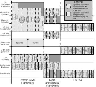
2.22 Representation of the needs fullfiled by each tool presented during the state of the art . . 35
2.23 Representation of an ideal flow where each state of the art tools is positioned . . . 36
3.1 (A) Application represented as an oriented graph, (B) Task specification represented with the Array-OL formalism. . . 38
3.2 Example based on the task representation given Figure 3.1.B of how the input/output array are read/write. . . 39
3.3 Example of task execution time evaluation. . . 40
3.4 Architecture model generated by PARSE . . . 40
3.5 Design space exploration methodology. . . 43
3.6 Architecture library representation. . . 44
3.7 Example of the operation done by the code parallelization tool, which from a sequential C code produce a task graph. . . 45
3.8 Conversion of an architecture to a chromosome. Within this architecture the three nodes are connected to a NoC. The NoC is the HERMES NoC [154]. Two nodes are active and constructed around the microblaze and LEON processors, while the third node gives access to a DDR memory. . . 48
3.9 Representation of how the AI connect the IPs onto the interconnect. . . 49
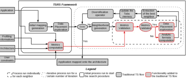
3.10 TSRS framework used to explore the application mapping solution space. . . 52
3.11 Example of Tabu movement used to generate the neighborhood. One task is moved at a time. Here the task 1 is moved from the node3 to the node0. . . 53
3.12 Communication cost for the ILP [197], Cluster + ILP [198], GMAP [114, 115, 116], PBB [175], Elixir [174], CGMAP [175], GBMAP [193], GAMR [96], A3MAP-GA [122], PSMAP [175], ACO [209], PMAP [131], BMAP [179],CHMAP [192], CMAP [68], CastNet [199],A3MAP-SR [122], NMAP [175], MOCA [186], SA [145], CSA [145], Onyx [123], LMAP [176], CTS and TSRS mapping algorithms on the tested benchmarks 60 3.13 Limit of the TSRS on the VOPD benchmark. From the initial solution (A), the task 2 is moved on the same node as the task 0 because all the solution are penalized and this is the most efficient penalized solution (B), the next solution (C) is then to move the task 0 to the free node since this is the only solution which is not penalized or Tabu. . . 61
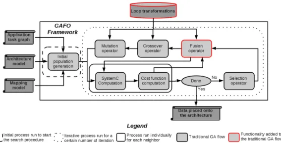
3.14 GAFO framework used to explore the application data placement solution space. . . 65
3.15 Loop transformations that can be applied to the application model. (A) Task fusion to merge tasks into the same fusion, (B) Tilling change add a level of depth to a loop nest, (C) The creation of a communication for data reorganization or data transfer.. . . 66
3.16 Conversion of a data placement to a chromosome, within this chromosome two tasks are merged within the same iteration space and one task is allocated into its own iteration space. . . 67
3.17 Operating principle of the fusion operator. . . 68
3.18 Chirp application task graph. . . 68
3.19 Jpeg application task graph.. . . 68
3.20 Stap application task graph. . . 69
3.21 Architecture models used for the chirp and jpeg application. . . 69
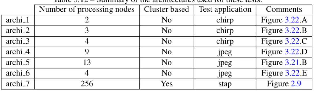
3.22 Architecture models used for the TSRS-GAFO experimentation. . . 73
3.23 Evolution of the proposed solution for the chirp, jpeg and stap application with the α parameters. . . 78
LIST OF FIGURES 17
4.1 FlexTiles architecture. The architecture is composed of two layer the MPSoC layer and the FPGA layer. GPP and DSP are mapped onto the MPSoC layer while the hardware accelerator are mapped onto the FPGA layer. All the resources are connected through a NoC, the accelerators (DSP and hardware accelerators) connection onto the NoC being
abstracted by the means of the AI. . . 83
4.2 Static cluster. . . 85
4.3 Management in FlexTiles: Cluster groups can behave differently depending on their dy-namicity level . . . 86
4.4 Accelerator Interface global view. . . 88
4.5 (A) Application model, (B) Architecture model of the proof of concept example. . . 91
4.6 Synchronization scheme and execution patterns. . . 92
4.7 FlexTiles board. . . 93
4.8 Vehicle registration plate, application tasks graph . . . 94
4.9 Vehicle registration plate input and output images . . . 94
4.10 Architecture implemented onto the FlexTiles platform. . . 94
4.11 Proposed architecture where clusters are implemented to favor local data transfer thereby increasing the overall system performance.. . . 100
4.12 Cluster architecture, each cluster is composed of a set of processor nodes along with a memory node. A processor node being composed of all the elements necessary to communicate and synchronize with the rest of the platform. . . 101
4.13 Memory node composed of a partition table, an address generation unit (AGU) and a memory protection unit (MPU) . . . 101
4.14 Structure of a line into the partition table. . . 102
4.15 Architecture of the address generation unit. . . 102
4.16 Architecture of the memory protection unit. . . 103
4.17 Example where two GPP within the same cluster are communicating through a partition of the memory node. . . 104
4.18 Example where a GPP and a DSP located into remote clusters are communicating through a memory node. . . 106
4.19 OVP model of cluster based architecture implementing an on-chip MP protocol. . . 107
4.20 Ter@ops architecture. . . 107
4.21 Flat architecture model used to compare the benefits brings by the cluster based archi-tecture. . . 108
4.22 2D-FFT application task graph.. . . 109
4.23 Execution times needed to realize a 2D FFT on 32 images. . . 110
4.24 Matrix multiplication application task graph.. . . 111
4.25 Execution times needed to realize 32 matrix multiplications. . . 112
4.26 Influence of the task mapping and data placement onto the benefit bring by the cluster based approach. . . 114
A.1 Evolution of the best solution with the diversification operator level for the stap application.135 A.2 (A) PIP, (B) VOPD, (C) MPEG-4, (D) DVOPD, (E) MWD, (F) mp3enc mp3dec, (G) 263enc mp3dec, (H) 263dec mp3dec. . . 136
A.3 (A) PIP architecture model, (B) VOPD, MPEG-4, MWD, 263enc mp3dec, mp3enc mp3dec, 263dec mp3 dec architecture model, (C) DVOPD architecture model. . . 137
A.4 Convergence of a population composed of 2000 individuals . . . 139
A.6 Impact of the mutation rate . . . 140
A.7 Impact of the fusion operator rate. . . 140
A.8 Chirp application task graph with loops details. . . 142
A.9 Jpeg application task graph with loops details. . . 142
A.10 Stap application task graph with loops details. . . 143
A.11 Chirp data placement obtained following the exploration done with the GAFO. . . 144
A.12 Jpeg input mapping used by the GAFO. . . 144
A.13 Jpeg data placement obtained following the exploration done with the GAFO. . . 145
A.14 Stap input mapping used for the GAFO. . . 146
A.15 Stap data placement obtained following the exploration done with the GAFO. . . 147
A.16 Initial and Final mapping obtained for the chirp application by the TSRS-GAFO for the three test case architectures. . . 148
A.17 Initial and Final mapping obtained for the chirp application by the TSRS-GAFO for the three test case architectures. . . 149
A.18 Jpeg data placement obtained following the exploration done with the TSRS-GAFO for the mapping shown Figure A.17 A and C. . . 150
A.19 Initial and Final mapping obtained for the stap application by the TSRS-GAFO. . . 151
A.20 Stap data placement obtained following the exploration done with the TSRS-GAFO for the mapping shown Figure A.19 . . . 152
B.1 Vehicle registration plate synchronization schemes and execution patterns. . . 155
B.2 Vehicle registration plate synchronization schemes and execution patterns. . . 156
B.3 Vehicle registration plate synchronization schemes and execution patterns. . . 157
B.4 Vehicle registration plate synchronization schemes and execution patterns. . . 158
B.5 2D-FFT application mapping on the clus 2 architecture . . . 159
B.6 2D-FFT application mapping on the Flat 2 architecture . . . 160
B.7 2D-FFT application mapping on the Ter@ops architecture . . . 161
B.8 Matrix multiplication application mapping on the clus 2 architecture . . . 162
B.9 Matrix multiplication application mapping on the Flat 2 architecture . . . 163
B.10 Matrix multiplication application mapping on the Ter@ops architecture . . . 164
List of Tables
1.1 Influence of the MPSoC architectures characteristics parameters. . . 7
2.1 Summary of the MPSoC architectures capabilities.In this table the MPSoC are evaluated following their capacities to ease the mapping and the data placement along with their ability to be scalable and target several applications with a reduce power budget.. . . 24
3.1 Variable names nomenclature . . . 41
3.2 Exploration runtime of the three test applications. . . 46
3.3 Tabu search parameters settings . . . 59
3.4 Exploration runtime of TS on the seven tested benchmarks . . . 62
3.5 Genetic algorithm parameters settings . . . 70
3.6 Application execution time for different memory configuration, along with the percent-age of the application execution time used for the computation and for the communica-tion. . . 71
3.7 Performance benefit bring by the FO. . . 71
3.8 Exploration runtime of the three test applications. . . 72
3.9 Profiling of the chirp application onto the PowerPC. Task numbering refer to figure 3.18. 74 3.10 Profiling of the jpeg application onto the PowerPC. Task numbering refer to figure 3.19.. 74
3.11 Profiling of the stap application onto the MPPA. Task numbering refer to figure 3.20. . . 74
3.12 Summary of the architectures used for these tests. . . 74
3.13 Execution time constraints set for all the application and architecture models. . . 75
3.14 Parameters settings for the TSRS and CTS. . . 75
3.15 Application execution time for different architecture model, along with the percentage of the application execution time used for the computation and for the communication. . . 76
3.16 Exploration run-time. . . 77
4.1 List of specific commands used to program the AI. . . 90
4.2 Area occupancy of one Accelerator Interface. . . 95
4.3 AI area consumption (Occupied slices) as relative ratio between components . . . 96
4.4 Latency of each elementary operation supported by the AI. . . 96
4.5 Mapping experimental Results . . . 97
4.6 List of evaluated architectures. The number of cores varies from 8 to 32. While the amount of memory present on the chip and the memory bandwidth stay constant. . . 108
4.7 Speedup of the cluster based architecture over the flat architecture and the Ter@ops on the FFT application. . . 110
4.8 Task overlap for the FFT application.. . . 111
4.9 Speedup of the cluster based architecture over the flat architecture and the Ter@ops architecture on the matrix multiplication application . . . 112
4.10 Task overlap for a matrix multiplication application.. . . 113
4.11 MMU resources consumption. . . 115
A.1 Evolution of the best solution with the memory size and the number of iteration for the stap application. . . 134
R´esum´e en franc¸ais
Contexte et motivations
Probl´ematiques
Les applications embarqu´ees incorporent de plus en plus de fonctionnalit´es impliquant diff´erents types de traitements `a r´ealiser. L’impact majeur de cette demande est l’´evolution croissante des syst`emes embarqu´es que cela soit en termes de performances et de capacit´e m´emoire.
De plus, aujourd’hui les applications deviennent de plus en plus dynamiques. Les temps d’ex´ecution sont alors d´ependants de param`etres non pr´edictibles au moment de la d´efinition de l’application. La d´etermination du temps d’ex´ecution de l’application devient d`es lors impossible, et seule une borne sup´erieure pour le temps d’ex´ecution peut ˆetre d´efinie.
L’´evolution des syst`emes embarqu´es entraˆıne donc des probl`emes au niveau de la conception et de la programmation. Ces syst`emes doivent en effet trouver un compromis entre leurs capacit´es (puissance de calcul, dynamicit´e) et les contraintes du domaine d’application (silicium, consommation).
La probl´ematique, li´ee `a la puissance de calcul, fut la premi`ere `a ˆetre adress´ee. Dans le cas de pro-cesseur monolithique, les principales approches consistent `a augmenter la fr´equence de fonctionnement du cœur de calcul ou `a augmenter la capacit´e m´emoire pour limiter le nombre de cycles inutilis´es du processeur. Cependant ces techniques, bien qu’efficaces, augmentent dans le mˆeme temps la surface du cœur de calcul le de petits cœurs permet d’atteindre la puissance de calcul d’un seul cœur monolithique tout en r´eduisant la consommation ´energ´etique et la surface consomm´ee.
Grˆace `a cette ´evolution, les architectures MPSoC apparaissent actuellement comme les principaux promoteurs de la r´evolution industrielle des semi-conducteurs [212]. Ces plates-formes contiennent plusieurs processeurs, g´en´eralement h´et´erog`enes, des ´el´ements de traitement avec des fonctionnalit´es sp´ecifiques refl´etant la n´ecessit´e du domaine d’application pr´evu, une hi´erarchie m´emoire et des com-posants d’entr´ees/sorties. Tous ces ´el´ements ´etant li´es les uns aux autres par une interconnexion sur puce (de plus en plus souvent un r´eseau sur puce ou “NoC” ).
Grˆace `a leurs ´evolutivit´es, leurs hautes performances, leurs capacit´es de parall´elisme `a un tr`es haut niveau d’int´egration et leur enveloppe ´energ´etique restreinte ces architectures deviennent de plus en plus populaires. Elles r´epondent aux besoins de performances des applications multim´edia, des architec-tures de t´el´ecommunication, de la s´ecurit´e du r´eseau et de nombreux autres domaines d’application. L’industrie est elle aussi consciente de la n´ecessit´e d’utiliser des architectures ”MPSoC” dans le but d’augmenter le rapport performance - ´energie des syst`emes embarqu´es o`u les contraintes de
tion sont plus ´elev´ees [138].
Cependant, la conception d’une architecture ”MPSoC” faible consommation et supportant les per-formances requises, n’est pas ais´ee. Cet ´equilibre d´epend en effet de nombreux param`etres tels que le nombre de cœurs de calcul, l’enveloppe ´energ´etique globale, le type de r´eseau d’interconnexion, l’architecture de la hi´erarchie m´emoire, le d´eploiement de l’application sur le syst`eme. En outre, le coˆut de fabrication de ce type de plateforme est cons´equent (surtout dans les technologies modernes) et implique la v´erification de mani`ere pr´ecise de chaque choix architectural et applicatif.
Le probl`eme de la consommation d’´energie dans les architectures MPSoC vient du fait que l’enveloppe ´energ´etique n’a pas suivi la mˆeme ´evolution que le nombre de cœurs [50]. Les solutions, afin de r´eduire la consommation d’´energie, ont ´et´e pleinement ´etudi´ees [86], l’une des principales approches afin de r´eduire la consommation ´etant le ”voltage scaling”.
Les acc`es m´emoires sont aussi un des facteurs critiques de la performance des architectures MPSoC [189], les gains en terme de puissance de calcul outrepassent fortement ceux de la m´emoire. En effet, si la puissance de calcul double tous les deux ans, celui de la m´emoire double tous les six ans [111,149]. En cons´equence, les acc`es `a la m´emoire g´en`ere des d´elais important pour lire ou ´ecrire les donn´ees vis-`a-vis des temps de calcul.
Dans les architectures MPSoC actuelles, les deux architectures principalement utilis´es sont les mod`eles `a m´emoire partag´ee et `a m´emoire distribu´ee. Cependant, le choix entre ces deux mod`eles est complexe car il d´epend `a la fois de l’application, du r´eseau d’interconnexion et de la puissance de calcul des cœurs. Le choix d’un r´eseau d’interconnexion est un autre point crucial au moment de la d´efinition d’une ar-chitecture MPSoC. En effet, le choix d’une topologie est d´ependant du nombre de cœurs qui doivent ˆetre connect´es sur le r´eseau mais aussi des caract´eristiques de l’application. Dans le domaine des syst`emes embarqu´es, trois principales familles pour les r´eseaux d’interconnexions existent: (1) Les connections point `a point, (2) les bus et (3) les NoC.
Une fois, l’architecture MPSoC d´etermin´ee, la difficult´e r´eside dans le fait de tirer pleinement parti de cette derni`ere. `A cette fin, le placement d’applications sur des architectures MPSoC `a ´et´e fortement ´etudi´e dans la litt´erature [175]. En fonction du moment ou sont assign´ees les tˆaches sur les coeurs de calcul, les techniques de placement de tˆaches sont statiques ou dynamiques.
Dans le cas de placement de tˆache dynamique, l’assignement et l’ordonnancement des tˆaches sur les processeurs sont r´ealis´es durant l’ex´ecution de l’application. Le placement de tˆache dynamique essaye donc de toujours trouver les goulots d’´etranglement de la performance et de r´epartir la charge de calcul sur l’ensemble des processeurs.
Dans le cas de placement de tˆache statique, le placement des tˆaches sur les cœurs de calcul est r´ealis´e hors-ligne, avant l’ex´ecution de l’application sur l’architecture. Pour une application donn´ee et une infrastructure de communication d´etermin´ee, les algorithmes essayent de trouver le meilleur placement de tˆaches au moment de la conception de l’architecture.
Finalement, un des derniers d´efis lors de la conception d’une architecture MPSoC est le placement des donn´ees. Le placement des donn´ees est en effet un point cl´e afin d’ˆetre en mesure d’atteindre des hautes performances de calcul et d’avoir une utilisation efficace des ressources mat´erielles. Comme le placement des donn´ees est `a la fois d´ependant du r´eseau d’interconnexion, de la taille et de la bande passante des m´emoires ainsi que de l’efficacit´e du processeur, le placement des donn´ees `a un impact
iii fort sur le placement des tˆaches et sur les choix architecturaux. Un placement de donn´ees id´eal est un placement de donn´ees ou le temps de traitement des donn´ees est sup´erieur o`u au moins ´egal au temps de transfert des donn´ees.
Comme nous pouvons le voir, les architectures MPSoC soul`event des d´efis importants que ce soit au niveau de la conception ou de la programmation. De plus, ´etant donn´e que ces param`etres (Nombre de cœurs, hi´erarchie et taille m´emoire, r´eseau d’interconnexion, placement des tˆaches et des donn´ees) s’influencent mutuellement l’exploration de l’espace de conception des architectures MPSoC devient difficile.
En effet choisir le nombre de cœurs d’une architecture MPSoC doit ˆetre fait au regard du parall´elisme de l’application mais aussi vis-`a-vis de la bande passante de la m´emoire et du r´eseau d’interconnexion. Cependant, le parall´elisme pouvant ˆetre atteint par l’application est d´ecid´e en fonction du placement des tˆaches et des donn´ees, des tailles m´emoires et des caract´eristiques inh´erentes de l’application.
Il apparaˆıt clairement que la modification de l’application ou de l’un des param`etres caract´eristiques de l’architecture entraˆıne la r´e´evaluation compl`ete de la solution. Ce qui dans les premi`eres phases de d´eveloppements d’une architecture MPSoC est prohibitif et consommateur en terme de temps.
De plus, ces d´efis de conception deviennent de plus en plus vrai avec l’´emergence des architec-tures MPSoC h´et´erog`ene. En effet, ces architecarchitec-tures ne se contentent plus de r´epliquer plusieurs fois le mˆeme cœur de calcul mais incluent des fonctionnalit´es sp´ecifiques (”Intellectual Property” (IP)) d´edi´ees `a un domaine d’application particulier, car elles pr´esentent un meilleur niveau de performance et une meilleure efficacit´e ´energ´etique [138].
Cette h´et´erog´en´eit´e en d´epit des b´en´efices apport´es augmente la difficult´e de concevoir et program-mer les architectures MPSoC. En effet, l’architecte doit: (1) Choisir entre plusieurs types de cœurs de calcul, (2) D´ecider s’il est plus b´en´efique de placer des tˆaches sur des GPP ou des acc´el´erateurs mat´eriels. La construction de l’architecture est aussi compl`etement diff´erente ´etant donn´ee que l’h´et´erog´en´eit´e de chaque composant doit ˆetre abstrait au niveau du r´eseau d’interconnexion. Ce qui implique de d´efinir entre chaque cœur de calcul et le r´eseau d’interconnexion un ”wrapper” particulier. Le ”wrapper” devant ˆetre red´efini chaque fois que le r´eseau d’interconnexion est chang´e.
En outre, la programmation des architectures MPSoC h´et´erog`enes est difficile ´etant donn´e que la mani`ere de programmer un acc´el´erateur mat´eriel ou un processeur g´en´eraliste (GPP) est diff´erent. L’utilisateur doit prendre pleinement parti de ces diff´erences afin d’utiliser au maximum ces architec-tures. Ainsi, les temps de d´eveloppement ´evoluent de mani`ere exponentielle ainsi que les temps de mise sur le march´e.
Tous ces d´efis durant la conception des architectures MPSoC mettent en lumi`ere le besoin d’une m´ethodologie d’exploration d’espace de conception aidant l’utilisateur `a d´efinir et `a programmer ces ar-chitectures. Il devient alors n´ecessaire de d´efinir un outil d’exploration d’espace de conception (DSE) facilitant l’interaction entre l’application et l’architecture pour r´eduire efficacement le nombre de solu-tions s’offrant `a l’utilisateur et les temps de mise sur le march´e.
De plus comme les architectures MPSoC deviennent de plus en plus h´et´erog`enes, il est n´ecessaire de d´evelopper des modules mat´eriels permettant de faciliter la construction et la programmation des architectures MPSoC h´et´erog`enes.
Contributions
Dans le cadre de cette th`ese, notre contribution est la d´efinition d’une m´ethodologie d’exploration d’espace de conception. Cette m´ethodologie DSE a pour but de d´efinir `a la fois une architecture mat´erielle et son code binaire ex´ecutable `a partir de trois entr´ees: (1) le code C s´equentiel d’une application, (2) une librairie d’architectures, (3) un fichier de contraintes.
Les principales caract´eristiques de notre m´ethodologie DSE est la consid´eration de mani`ere conjointe de toutes les contraintes relatives `a la d´efinition d’une architecture mat´erielle grˆace `a une collaboration avec l’utilisateur. La m´ethodologie DSE propos´ee est en effet capable de: (1) g´en´erer une architecture compos´ee de plusieurs cœurs de calcul, (2) d´efinir un placement des tˆaches et des donn´ees ainsi que l’ordonancement associ´ees `a partir des contraintes utilisateurs.
´
Etant donn´e que ces param`etres s’influencent mutuellement, un outil nomm´e ”Parsimonious AR-chitecture Space Exploration” (PARSE) est propos´e afin de parcourir l’espace de solution. PARSE est construit autour de m´ecanismes r´ecursifs permettant depuis des simulations d’adapter l’architecture, le placement des tˆaches et des donn´ees, ceci dans le but d’atteindre le meilleur compromis `a la fois pour l’architecture et pour l’application. Pour ce faire la m´ethodologie de PARSE est semi-automatis´ee.
En effet, ´etant donn´e la taille de l’espace de solution, l’utilisateur aide PARSE en retirant de l’espace de solution l’ensemble des cœurs ne r´epondant pas aux besoins applicatifs.
PARSE, `a partir des choix de l’utilisateur, g´en`ere un ensemble d’architectures candidates, accom-pagn´ees d’un placemement des tˆaches et des donn´ees. Chaque solution potentielle est ´evalu´ee par le biais d’un simulateur SystemC afin de converger de mani`ere efficace vers le meilleur compromis `a la fois pour l’application et l’architecture. Cette exploration de l’espace de solution s’effectue de mani`ere automatis´ee grˆace `a des algorithmes ´evolutionnaires. Une fois le meilleur compromis identifi´e le code VHDL de l’architecture et le code binaire ex´ecutable associ´es sont g´en´er´es.
Parce que PARSE `a la capacit´e de g´en´erer des architectures mat´erielles, notre seconde contribution est la d´efinition de deux modules mat´eriels. Le premier module mat´eriel d´efini une unit´e de management m´emoire (MMU) servant `a abstraire la hi´erarchie m´emoire aux sein d’architectures organis´ees autour de clusters.
La d´efinition de cette MMU permet de faciliter la programmation des architectures MPSoC et d’optimiser le temps d’ex´ecution de l’application, en r´eduisant les goulots d’´etranglement, en maintenant la localit´e des donn´ees et en limitant les transferts de donn´ees `a travers la plateforme. Pour ce faire, l’architecture propos´ee est bas´ee sur des clusters o`u les processeurs sont regroup´es et connect´es au travers d’une m´emoire partag´ee. La coh´erence de la m´emoire ´etant assur´ee par le biais d’une MMU mat´eriel.
Le second module mat´eriel d´efini dans le cadre de cette th`ese est l’”accelerator interface” (AI) qui est une interface g´en´erique utilis´ee pour connecter diff´erents types de cœurs de calcul (GPP, DSP1 ou acc´el´erateurs mat´eriels) sur un r´eseau d’interconnexion.
L’AI permet de connecter de mani`ere efficace diff´erents types d’acc´el´erateurs et de processeurs sur un mˆeme r´eseau d’interconnexion sans tenir compte de leurs sp´ecificit´es ou caract´eristiques. L’AI propose une apprroche ”plug and play”, grˆace `a la d´efinition d’un mod`ele d’ex´ecution unifi´e et d’une architecture g´en´erique qui permet de ne pas tenir compte du cœur de calcul adress´e et de ses sp´ecificit´es.
v De plus, toujours dans le but de tirer pleinement parti de la puissance de calcul induite par les archi-tectures MPSoC, l’AI est autonome une fois initialis´e, ce qui permet de r´ealiser de mani`ere concurrente des traitements en parall`ele.
Le reste de ce document pr´esente en chapitre1le contexte et les motivations derri`eres cette th`ese. Le chapitre 2 pr´esente l’´etat de l’art des diff´erentes architectures MPSoC et des outils d’exploration d’espace de conception. Le chapitre 3 quant `a lui d´ecrit la m´ethodologie d’exploration d’espace de conception propos´e permettant d’explorer de mani`ere conjointe les aspects architecturaux et applicatifs. Le chapitre4pr´esente les contributions apport´ees au niveau mat´eriels. Pour finir le chapitre5dressent les conclusion et les perspectives de cette th`ese.
1
Introduction
Abstract: This introductory chapter first presents the context and the motivations behind this thesis. Finally the manuscript organization is given at the end of the chapter.
Contents
1.1 Context and motivations . . . 2
1.2 Manuscript organization . . . 10
1.1
Context and motivations
1.1.1 Problem statement
The embedded applications come up with more and more functionalities inducing various kinds of computations to realize. The major impact of these new application needs is the steadily evolution of the embedded systems performances in terms of computing power and memory capacity. The Figure1.1
[107] shows the computing power needs depending on the application for various application domains.
Figure 1.1 – The graph shows the computational requirements of different application grouped by appli-cation domains [107].
For example in the telecom domain the application computing power needs to increase to get around 100 giga operation per second (GOPS) for the video broadcasting applications. The same trend is also observed for the multimedia applications, due to the image size and to the algorithm complexity increase. For example the 3D graphics applications require more than 1 tera operation per second (TOPS). The same evolution of the computing power affects all the embedded applications domains whether for the vision applications or the military applications.
Moreover today an embedded system has to handle several kinds of applications at the same time on the same chip. For example a mobile is no longer just used as a phone, but also used to read mails, go on internet, watch movies or play video games. These demands impose the embedded systems to run several applications which come from several applications domains.
Furthermore the applications become more and more dynamic. Indeed the application executions time is dependent of not predictable parameters at the time the program is written. It is then not possible to predict the execution time of an application and it is usually only possible to determine an upper bound for the processing time. This dynamicity is more and more present in the graphic domain where
Context and motivations 3 the algorithms adapt their computation to the data to be processed, as DVS1for 3D video games [106] for example. This application dynamicity implies that no optimal scheduling solution can be found off-line, and so the system control as to also be dynamic in order to enable an on-line optimization.
The embedded system evolution leads to a problem at the conception level. Indeed these systems have to find a trade-off between their capacity (computing power, dynamicity) and the embedded system constraints (silicium, consumption). The computing power is one of the major issues.
In order to increase the computing power of a single core architecture the solution is to improve its operation frequency or to raise the size of the memory in order to limit the idle cycle of the processor. These techniques increase, at the same time, the silicium area and the processor power consumption, which then decrease the energy efficiency [50].
Since energy efficiency is a key aspect of an embedded system, the solution is then to use a multi or a manycore architecture. Indeed as stated by [50] it is easier to integrate several little core specialized or not, whose energy and area efficiency are optimized. This allows to reach a computing power equal to the one of a single processor within a reduced power and area budget.
Following this trends, the multiple processors system on chip (MPSoC) architectures (Figure 1.2) appears as a major promoter of the industrial revolution of semiconductors as advised by the international technology road-map for semi-conductors (ITRS) [212]. This relies on the integration on the same chip of several complex functionalities. These platforms contain multiple processors, a memory hierarchy, and I/Os components. All these elements linked to each other by the means of an interconnect infrastructure becoming more and more often a network on chip (NoC).
Figure 1.2 – Typical MPSoC architecture based on several GPP connected through an interconnect (Bus or Noc based) along with a DDR memory and all the peripherals needed for a connection with the outside environment. These MPSoC is homogeneous and can target several kinds of computation.
Due to their performance, MPSoC gain popularity, and are now present in various domains of ap-plications. Industry is aware of the need of using multi-core and shortly manycore chips to raise the performance/power ratio especially in embedded systems when power consumption is one of the main constraints [138].
However the design and the programming of a high performance low power MPSoC architecture is not easy. Having several cores on a single chip raises numerous problems and challenges. Power and temperature management are two concerns that can increase exponentially with the addition of cores. Memory hierarchy and data placement is another challenge, in order to avoid any bottleneck at the
2 000 1 980 1 985 1 990 1 995 2 005 2 010 2 015 100 101 102 103 104 105
Frequency of the computation unit Memory speed
Figure 1.3 – Evolution of the memory performance in regards of the processor performance [111].
memory port and onto the interconnect. The choice of an interconnection network is also deterministic in order to be scalable with the number of cores and to sustain the bandwidth request. Finally, using a MPSoC to its full potential is another issue, if programmers don’t write applications that take full advantage of the multiple cores.
The power consumption problem known as the “Power Wall”, is due to the fact that the power envelope does not follow the same trend as the number of cores [50]. In order to overcome this ”Power Wall” a set of initiative has been proposed [86].
Memory is also a critical factor for overall performance of MPSoC architectures [189], the gain in speed of calculation units far exceeds memory ones. As shown (Figure1.3), if the speed of calculation units doubles every two years, memory one doubles every six years [111,149].
In consequence the access time to the memory usually causes important access time to read or write data, compared to the processing time. This divergence in performance between the memories and computation units is called ”memory wall”. In current MPSoC architectures two main memory models are used depending of the architecture and of the running application:
• The shared memory (SHMEM) model: where a memory is simultaneously accessed by multiple processors for data transfer and for synchronization.
Context and motivations 5 • The distributed memory model: which combines each core with its own local memory (LMEM)
and there is no global memory or address space.
A shared memory model eases the programming of the platform since all the processors share the same view of the architectures. However over a certain number of cores a physically shared memory leads to bottlenecks onto the network and at the memory ports. These bottlenecks then limit the scala-bility of the memory model in context of MPSoC architectures.
The distributed memory model on the other hand is much more scalable. However the difficulty to program this model is increased. Indeed the programmer has to think about the processors synchroniza-tions, the data location and transfers in order to ensure the consistency of the application execution time. To overcome these programming difficulties one possible solution relies on the use of a virtualization layer to expose at the software level a shared memory space.
However choosing between those two memory models is then quite difficult since the choice is fully dependent of the application, the interconnect bandwidth and of the processing cores capabilities.
The choice of an interconnection network is another crucial point when defining a MPSoC architec-ture. Indeed the choice of a topology is dependent of the number of cores that have to be connected to the interconnect and is also dependent of the application characteristics. In the embedded system field three mains on-chip interconnection families exist: (1) the point to point connection, (2) the bus and (3) the NoC.
Figure 1.4 – Point to point interconnection network
The point to point connection creates a dedicated communication link between each element to in-terconnect (Figure 1.4). Thus, when a communication must be made, the sender places the message on the dedicated link and the receiver returns a confirmation of reception. These kinds of connection have the advantages of being extremely efficient since no communication link is limited. However this solution is not scalable. Indeed the number of links between the cores quickly becomes significant and the consumed silicium area unacceptable.
Unlike point to point interconnect, bus based architecture seeks to share communication resources (Figure1.5). A bus architecture is composed of two major elements an arbitrator and a communication link. So when a core wants to send a message over the bus, it first consults the arbitrator. Once it has received the authorization, it sends the message onto the bus. At all times there is one message on the communication medium, and several arbitration policies exists depending of the needs of the user (FIFO2, TDMA3, Priority levels ...).
The main advantage of the bus is its simplicity and the fact that only one link is used to connect all the elements between each other. However over a certain number of cores the scalability of the bus is
2. first in first out
Figure 1.5 – Bus interconnection network
limited due to the latency needed to access the bus.
Due to the limitations of bus and point-to-point interconnection network, respectively regarding the performance, area and scalability, the NoC were proposed. NoC are derived from network between computers. The basic idea is to transfer the information over the network in the form of messages divided in packets. As Ethernet networks, the NoC consist of a set of links and routers enabling communications between the elements (Figure1.6).
Figure 1.6 – Representation of a NoC
A network interface (NI) is placed between the core and the router to format the message and man-aged the communication. This modularity allows the addition of new communicating elements without having a significant impact on performance as for the bus. Furthermore, the addition of elements is done with a minimum of links which limits its cost unlike point to point connections. The main difficulty with a NoC relies in the routing policies and the way to ensure a certain quality of services [91].
Once the architecture of the MPSoC determined, the difficulty is to take full advantage of the multiple cores present onto the chip. To that end application mapping is studied by the state of the art [175]. The problem of application mapping is NP-hard [166]. Depending on the time at which the tasks are assigned to the computing cores for processing, the mapping techniques can be classified as dynamic or static mapping.
In case of on-line or dynamic mapping, the assignment and ordering of tasks are performed during the execution of the application. Dynamic mapping always tries to detect the performance bottlenecks and distribute the workload among the processors. As the mapping depends on the current load of the processors, it should result in a better solution. However, the computational overhead of the mapping algorithm may increase the delay and energy consumption of the application at run-time.
Context and motivations 7 the application runs. For a given application and a target communication infrastructure, static mapping always tries to define the best placement of tasks at design time. As the mapping is completed before execution, the mapping algorithm is executed only once and no overhead implies at run-time.
Finally another challenge when programming a MPSoC architecture is the data placement. The data placement defines based on the memory hierarchy where the data needed by processors are located, how the processors access it and the data transfers needed to ensure the memory consistency and the performance. The data placement is a key point to reach both high performances and to define hardware efficient architectures. Since the data placement is dependent of the interconnect, of the memory size and bandwidth and of the processor efficiency, the data placement has a big impact on the architecture and on the application definition.
An ideal data placement being a placement where the data transfers are minimal and where the time needed to process the data is greater or at least equal to the time needed to transfer them.
The MPSoC architectures, raise significant design and programming challenges in order to take full advantages of their capabilities. Moreover since these parameters (numbers of cores, memory hierarchy and size, interconnect, task mapping, data placement) mutually influence each other the design space exploration (DSE) of MPSoC architecture is becoming cumbersome.
Indeed choosing the numbers of cores of a MPSoC, must be done with regards to the application parallelism but also of the memory and interconnect bandwidth. However the application parallelism that can be achieved is decided in regards of the data placement, the task mapping, the memory size and of the inherent characteristics of the application.
Table 1.1 – Influence of the MPSoC architectures characteristics parameters. Impacted parameters
Mapping Data Nb of Type Interco Mem
placement cores of cores bw bw
Impacting parameters Archi Interco hierarchy ! ! ! ! Mem hierarchy ! ! ! Nb of cores ! ! Appli Type of cores ! Mapping ! Interco bw ! ! Mem bw ! !
As it can be seen in table1.1, it clearly appears that a modification of the application properties or of one of the characteristic parameters of the architecture will force the designer to reevaluate its entire solution. This activity done during the early stages of development of a MPSoC architecture is long and time consuming.
Furthermore these design challenges are becoming more complicated with the emergence of hetero-geneous MPSoC architectures (Figure 1.7). Indeed these architectures do not simply replicate several times the same core, but includes specific features reflecting the need of the intended domain of applica-tion, because they present better performances and are more power efficient [138].
This heterogeneity despite the performance benefit brought increases the difficulty to design and program MPSoC architectures. Indeed the designer has to: (1) choose between several types of cores, (2) decide if it is more beneficial to map a set of tasks to a general purpose processor (GPP) or to a hardware accelerator (Intellectual Property (IP)).
The construction of the architecture is also more difficult since the heterogeneity of each core have to be hidden at the interconnect level. This implies to create between each IP and the interconnect a particular wrapper. The wrapper has to be redefined each time the interconnect is changed.
Figure 1.7 – Typical heterogeneous MPSoC architecture.
Finally with heterogeneous architectures, the programming is also more difficult since the way to program a hardware accelerator or a GPP is quite different. Since the user has to take full advantages of these differences in order to fully use its architecture, the developing time is getting more important along with the time to market.
All these challenges during the definition of MPSoC architectures emphasize the needs of an auto-matic design process to help the user to design and program these architectures. It is then mandatory to define a DSE methodology which aims to define jointly the application and the architecture, to efficiently reduce the time to market and to prune the solution space by providing assistance to the designer. To that end the DSE methodology should be able to handle the:
• Data placement exploration to guide the user to the most efficient data placement. • Mapping exploration to guide the user to the most efficient task placement. • Architecture exploration to guide the user in the architecture creation process. • Heterogeneity of MPSoC architectures.
• Binary code generation from an architecture representation and an application description. • VHDL code generation from an architecture representation or an application C code.
• Scalability of MPSoC architectures by integrating new architectural or application models into its database.
• Performance evaluation by evaluating the performance of the application onto the architecture. Moreover since the MPSoC architectures are now becoming more and more heterogeneous it is necessary to develop hardware modules than can connect different cores together and address different applications domains at the same time, in order to ease the definition and the programming of heteroge-neous MPSoC architectures.
Context and motivations 9
1.1.2 Contributions
In the context of this thesis our contributions is the definition of a DSE methodology. This DSE methodology aims to define a hardware architecture and its associated executable binary code based on three inputs: (1) an application C code, (2) an architecture library and (3) a constraints file. It is however important to note that the proposed DSE methodology can also start with an already existing architecture and define the associated executable binary code.
The main features of our DSE methodology is the consideration of all the constraints related to the definition of hardware architectures thanks to a collaboration with the user. The proposed methodology is indeed able to: (1) generate an architecture composed of several processing cores potentially hetero-geneous, (2) define tasks mapping, a data placement and a scheduling based on the user constraints.
Given that all these parameters mutually influence each other a tool called PARSE (Parsimonious architecture solution space exploration) that explores the design space has also been defined. PARSE is constructed around recursive mechanisms allowing, based on simulations, to adapt the architecture, the tasks mapping, the data placement in order to get the best compromise for both the architecture and the application. To that end, a semi-automated approach is proposed.
Indeed since the design space is huge, the user helps PARSE by removing from the solution space the cores that does not match the needs of the application. Once done the user defines for each application task a set of potential core (processors or IPs) that can run it.
PARSE based on the choices made by the user, generates candidate architectures, along with a task mapping and a data placement. Each potential solution provided being evaluated by the means of a SystemC simulator in order to converge to the best compromise for the application and the architecture. To autonomously go through the solution space PARSE uses evolutionary algorithms [101,102]. Once the best compromise identified, an executable binary code, along with the VHSIC4hardware description language (VHDL) code of the architecture is generated.
Because PARSE aims to explore and generates hardware architecture our second contribution is the definition of two hardware modules. The first one defines a hardware memory management unit (MMU) used to abstract the underlying memory hierarchy in context of cluster based architectures.
The definition of this MMU for cluster based architectures allows to ease the programming of MP-SoC architectures and optimize the application execution time by limiting the data transfer among the platform. To that end based on a MPSoC architecture where the processors are grouped into cluster con-nected to a memory, we propose to manage the consistency of the memory at the hardware level thanks to the use of the hardware MMU.
The second hardware module is the accelerator interface (AI) which is a generic interface used to connect the processing cores (DSP5or hardware accelerator) to an interconnect.
The AI allows to easily connect different kinds of accelerators and processors together without taking care of their specificity’s or characteristics. The AI then propose a plug and play approach, by defining a unified programming model and a generic architecture, that allows to disregard the IP specificity and the addressed interconnect.
4. very high speed integrated circuit 5. digital signal processor
Moreover still in order to take a full benefit of the computing power induced by MPSoC architectures, the AI behaves autonomously once initialized, which allows to realize concurrent processings in parallel.
1.2
Manuscript organization
The chapter2presents the state of the art of MPSoC architectures and of DSE tools. The different characteristics of the MPSoC architectures both at the architectural level and at the programming level are reviewed. This review is completed by a set of concrete examples, demonstrative of these differences. After this study, the state of the art of available DSE tools is depicted. In this section the tools are split into three families following their abstraction level. Based on this distribution the advantages and the drawbacks of each family along with the capabilities and the needs of each presented DSE tool are given.
After the study of the state of the art, we see that the conception and the programming of MPSoC architectures are difficult, error prone and time consuming. Moreover none of existing DSE methodology is able to handle at the same time the definition of the application and of the architecture which leads to a separation of concerns. To face these limitations the chapter 3presents a DSE methodology able to simultaneously define the application and the architecture. To enable this simultaneous definition and methodology PARSE tool is proposed. PARSE is based on recursive mechanisms and on a parsimonious representation of the solution space to define autonomously and simultaneously the application and the architecture.
Still with the aims to ease the access to MPSoC architectures the chapter4presents the FlexTiles project and the two hardware modules designed in the framework of this project. Indeed the MPSoC architectures present a lot of heterogeneity which greatly increases the difficult to conceive and program these architectures. To that end the first propose hardware module is used to abstract the heterogeneity of the processing core connected onto the interconnect. The second hardware module is used to propose an alternative memory management model to help to overcome the so called memory wall.
Finally, the chapter5concludes this manuscript by summarizing the contributions of our works and opportunities beyond this thesis.
2
State of the art
Abstract: The increasing amount of complex applications, has forced the designers to define ar-chitectures with high performance constraints. The embedded paradigm introduces new constraints and these architectures have to provide high performance throughput, without using a lot of hardware re-sources and within a very limited power budget. To reply to these needs the MPSoC architectures appear as a main solution. In order to clearly identify the difference between these architectures this chapter first gives a brief introduction. In a second time a MPSoC architecture classification along with the main example of current MPSoC architectures are described. Finally we present the design space exploration tool flow used to program and design these architectures.
Contents
2.1 Introduction. . . 12
2.2 MPSoC architectures . . . 12
2.3 Design space exploration tool flow . . . 25
2.4 Summary . . . 36
2.1
Introduction
This chapter presents the state of the art of current MPSoC architectures and DSE tool flow. The first section presents the MPSoC architectures and focus more particularly on their: (1) number of cores and heterogeneity, (2) memory, interconnect, and architecture hierarchy, (3) management and programming. The second part on the other hand focuses on how existing DSE tools flows help to program and conceive current MPSoC architectures.
2.2
MPSoC architectures
2.2.1 Introduction
Figure 2.1 – Non-exhaustive list of the evolution of the multiple cores architectures in regards of their number of cores and their year of production [107].
The evolution of the computing power of the MPSoC architectures as stated by the ITRS is tremen-dous as shown on Figure 2.1. Among all the architectures the goal is to provide a maximum com-puting power. To that end several execution models (data flow, sequential) and physical structures
MPSoC architectures 13
Figure 2.2 – Classification of the MPSoC architectures [74].
(SMP1,CMP2,CMT3) have been proposed.
These architectures though all based on multiple cores presents fundamental differences at the hard-ware and programming levels. In order to present a clarified view of the current state of the art we then propose to use the classification of the MPSoC architectures proposed in [74] (Figure2.2).
This classification is divided into two categories the multiple tasks and the single task processors. The multiple tasks processors regroup the architecture composed of several processors, each one able to execute several tasks at the same time. The single tasks processors regroup the architecture composed of several processors able to execute only one task at a time but several tasks into the time. The single task processors then have an atomic vision of the execution flow while the multiple tasks processor does not. The single task processors can be either based on a symmetric multiprocessing (SMP) or a chip multi-processing (CMP) approach, which allow to shows two different execution models. The main difference between these two models come from the fact that within a SMP architectures the same cores are used for control and processing while within a CMP architectures some cores are dedicated to processing and some cores to control.
The CMP architecture can be either homogeneous or heterogeneous. Finally all these single task processors are either based on a distributed memory model or on a shared memory model.
The rest of this section depicts more in details the distinctions made between the several MPSoC architectures and gives concrete examples.
2.2.2 Single task processor
2.2.2.1 Symmetric multiprocessors
The association of several identical single task processors onto a shared interconnect is called a ho-mogeneous architecture. These architectures allocate statically or dynamically the tasks onto the different
1. Symmetric multiprocessor 2. Chip Multiprocessor 3. Chip Multithreading
![Figure 1.1 – The graph shows the computational requirements of different application grouped by appli- appli-cation domains [107].](https://thumb-eu.123doks.com/thumbv2/123doknet/7977481.267292/29.892.174.724.347.706/figure-computational-requirements-different-application-grouped-cation-domains.webp)
![Figure 1.3 – Evolution of the memory performance in regards of the processor performance [111].](https://thumb-eu.123doks.com/thumbv2/123doknet/7977481.267292/31.892.153.698.184.624/figure-evolution-memory-performance-regards-processor-performance.webp)
![Figure 3.12 – Communication cost for the ILP [197], Cluster + ILP [198], GMAP [114, 115, 116], PBB [175], Elixir [174], CGMAP [175], GBMAP [193], GAMR [96], A3MAP-GA [122], PSMAP [175], ACO [209], PMAP [131], BMAP [179],CHMAP [192], CMAP [68], CastNet [199](https://thumb-eu.123doks.com/thumbv2/123doknet/7977481.267292/87.892.145.763.146.979/figure-communication-cluster-elixir-cgmap-gbmap-psmap-castnet.webp)