an author's
https://oatao.univ-toulouse.fr/26736
https://doi.org/10.1016/j.jcomc.2020.100031
Bouvet, Christophe and Serra, Joël and Garcia-Perez, Pablo Strain rate effect of mode II interlaminar fracture
toughness on the impact response of a thermoplastic PEEK composite. (2020) Composites Part C: Open Access, 2.
ISSN 2666-6820
Strain
rate
effect
of
mode
II
interlaminar
fracture
toughness
on
the
impact
response
of
a
thermoplastic
PEEK
composite
C.
Bouvet
a,∗,
J.
Serra
a,
P.
Garcia
Perez
a,ba Université de Toulouse, Institut Clément Ader, ISAE-SUPAERO – UPS – IMT Mines Albi – INSA, 10 av. E. Belin, 31055 Toulouse, France b Arts et Métiers ParisTech, I2M, Talence, France
Keywords:
Strain rate effect Carbon/PEEK composite Fracture toughness Impact
Delamination
a
b
s
t
r
a
c
t
Recentadvancementsincompositeproductionandprocessingaremakingthermoplasticsaviableoptionina widerarrayofaerospaceapplications.Inparticular,CarbonFibreReinforcedPlastics(CFRP)withthermoplastic resinarebelievedtohavebetterdamagetolerancepropertiesthanthermosets.However,fewstudieshavebeen conductedregardingthenumericalmodellingofthebehaviourofsuchmaterialssubmittedtolowenergyimpacts. HeretheDiscretePlyModel(DPM),thatpredictsthefailureoflaminatedcompositeswiththehelpofcohesive elements,isusedtocomparethermosettingandthermoplasticsimpactdamagetolerances.TheDPMisimproved totakeintoaccountthestrainrateeffectofthefracturetoughness(FT)inmodeIIofinterlaminarinterfaces.First, theEndNotchedFlexure(ENF)testthatinducesunstablecrackgrowthisusedbothtoexperimentallymeasure thevalueofFTinmodeIIforhighspeedcrackgrowthandtoidentifythestrainrateeffectusedinthemodel. Second,theDPMisthenusedtosimulateimpacttestsforvariousstackingsequences([452 ,−452 ,02 ,902 ]2S ,[02 , 452 ,902 ,−452 ]2S ,[02 ,302 ,902 ,−302 ]2S and[902 ,−452 ,02 ,452 ]2S )andimpactenergylevels(10,20and30J). Goodcorrelationswithexperimentareobservedintermsofforce/displacementcurvesanddelaminatedareas. Thenumericalmodelcorrectlydescribestheasymmetryofthedelaminatedinterfacesandthepropagationof groupsofinterfaceslocatednearthemid-thicknessofthelaminatedplates.Finally,thedamageassociatedwith a30Jimpactiscomparedforthecarbon/PEEKofthisstudyandclassicalcarbon/epoxyplatesusingnumerical simulations(DPM).Nosignificantdifferencehasbeenfound.Theresultscorroboratethoseobtainedinprevious studiesshowingtherelativelylowvalueofFTinmodeII,usinganENFtestandinfraredthermography(IRT). Thisarticlethereforequestionstheapparentsuperiorityofcarbon/PEEKlaminatedcompositesovercarbon/epoxy laminatedcompositesintermsofimpactdamagetolerance.
1. Introduction
High-performancecompositeswiththermoplasticresinarebeing in-creasinglyusedincompositestructures,inparticularinthe aeronauti-calfield.Semi-crystallinethermoplasticpolymers,suchasPEEKresins, haveadvantagesoverclassicalthermosetresins,suchasepoxies:good damageandimpacttolerance[1,2],a highdegree ofchemical resis-tance,noexpirydate,a usabilityovera largerangeoftemperatures andapossiblerecyclingthroughremelting.InthecaseofPEEK,its bio-compatibilityalsomakesitaperfectcandidateforcompositetrauma devicessuchasorthopaedic,dental,spinalandcranialimplants[3,4]. Classically,theliteraturestatesthatthermoplasticcomposites showa bettertolerancetoimpactdamagethanepoxybasedcomposites[5,6]. Themainpropertiesdrivingtheimpacttoleranceofcompositelaminate, i.e.themodeIandmodeIIfracturetoughness(FT),GIcandGIIc,are
∗ Correspondingauthor.
E-mailaddress:[email protected](C.Bouvet).
themostimportant[2,7–12].TheFTofthermoplasticresinsisclearly higherthanthatofthermosetresins,particularlyiftheneatresinis con-sidered.Forexample,themodeIFTisabout4N/mmforneatPEEK resincompared toabout0.1N/mmforneatepoxy resin[11]. How-ever,thedifferencediminisheswhenfibresareadded.Friedrichetal.
[13]haveshownthat carbonfibreprepegwithPEEKresinis“only” about 10times moreresilient(modeIandmode IIFT)thancarbon fibreprepegwithepoxy resin(Fig.1a),forasimilarfibrecontentof approximately 64%.Carbonfibrewovenplies alsofollowthis trend: modeIandmodeIIFTareabout1.6N/mmand2.5N/mm, respec-tively,forcarbon/PEEKcomposite,comparedtoabout,0.5N/mmand 1.5N/mmforcarbon/epoxycomposite,forasimilarfibrecontentof ap-proximately50%[11].Thisevolutioncanbeexplainedbytheincrease oftheinfluenceoffibresondamagepropagation.Thedelaminationcan only evolvebetweenplies onaprepeg-basedlaminate andthecrack
Fig.1. EffectofthecrackgrowthspeedonmodesIandIIFTforcarbon/epoxyandcarbon/peekcomposites(a)[13],andductile(b)andbrittlebehaviour(c)of delaminationofPEEKresin[29].
propagationpathisevenmoreconstrainedbytheundulatedpatternof theyarnsforthecaseofwovenplies[11].Itisgenerallyacceptedin theliteraturethattheinitialdamageduringimpactloading,associated withdelamination,ismainlydrivenbytheinterlaminarFTinmodeII. Therefore,thehigherFTofthermoplasticcompositesinshearingmode makesthemgoodcandidatesforimpacttolerance[14].
However,someresultsrecentlyreportedintheliteratureshowthat thesuperiorimpacttoleranceofcarbon/thermoplasticlaminated com-positescomparedtothatofcarbon/epoxylaminatedcompositesisnot soobvious.Forexample,Vieilleetal.comparedtheimpactdamageof compositelaminateswithwovencarbonand3typesofresin:2 ther-moplasticones(PEEKandPPS)anda thermosetone(epoxy) [9,10]. Althoughbetterresistancetoimpactwasexpectedfromthe thermoplas-tics,theresultsshowsimilarbehaviourforthe3materials.Theauthors explainthatthesmalldifferenceobservedbetweenthese3laminates couldbe dueeithertothewovennature ofthepliesor tothesmall thicknessoftheplates(about2mm),comparedtotheclassical thick-ness(4mm)usedforstandardtests[15].Anotherexplanationofthe smalldifferencebetweenimpactresistanceofthermoplasticand ther-mosetcomposites couldbethestrainrateeffectof thethermoplastic resinsontheinterlaminarFT,particularlyinshearingmode.
Itiswellestablishedthatthemechanicalpropertiesofpolymersare verydependantontemperature,strainrateandpressure[16,17].Strain rateoftenhasaninfluenceonthefracturebehaviourofboth
thermoset-[18]andthermoplastic-basedcomposites[19–23].Afewconfigurations seemtobestrainrate-independent[24–27],behaviourthatmightbe duetofibrebridgingin unidirectionalspecimens[22]ortothe rela-tivelylowstrain-ratesinvestigated.ThereviewbyW.J.Cantwelland M.Blytononvariousthermosetandthermoplasticresinbased compos-itesrevealsthat, onaverage,thefracturetoughnessof brittlematrix
compositesiseitherrate-insensitiveorincreasesslightlywithloading rates [28].Incontrast,thermoplastic matricesexhibitareductionin fracturetoughnesswithincreasingstrainrates.AccordingtoPloeckl,at lowtemperaturesorathighstrainrates,themolecularmovementsof thepolymerchainsarerestrictedand,consequently,theoverall mate-rialbehaviourshowsarigidandbrittleresponse[20].Withincreasing temperatures,rotationsandtranslationaldisplacementsofsidegroups, smallmoleculargroupsorrepeatunitsinthemainpolymerchainare possible.Thedecreaseofthetemperatureisequivalenttotheincrease ofthestrainrate.Inpolymerphysicsliterature,thisisreferredtoasthe time-temperaturesuperpositionprinciple.
RegardingthespecificcaseofPEEKbasedcomposites,Hamdanetal. suggested thathighratetestinginducedachangein crystalline mor-phologyand,morespecifically,anincreaseofthecrystallinitydegree
[30]whichwouldthenbethecauseofthefracturetoughnessdecrease athighstrainrates.ElQoubaaetal.showedthatthedependency re-lationshipofPEEKmaterialpropertiesonstrainrateisnotlinear:the strainratesensitivityisgreaterathigherstrainrate(over100/s)[31].
Friedrichetal.[13]performedENFtestsofAPC-2PEEKresin uni-directional(UD)compositelaminateatdifferentloadingspeeds.They showedthatFTinmodeII(Fig.1a)ofcarbonfibre/PEEKdecreasedfrom 1.9to0.4N/mmwhenthecrossheadspeedincreasedfrom4.2×10−6to
9.2×10⁻²m/s.Theyexplainedthisresultbyanevolutionofthecrack
growthtype,fromductilepropagationatlowspeed(Fig.1b)tobrittle propagationathighspeed(Fig.1c).Hashemietal.reachedthesame conclusionswithacarbon/PEEKcompositeusingthecorresponding pa-rameteroftheloading-rate:thetemperature[24].Theirworkexhibited aclearincreaseinfracturetoughnesswhenthetemperaturerose.This isalsothecaseforgraphite/PEEKcompositesaccordingtotheanalysis ofMalletal.[32].
Fig.2. FTinmodeIIversuscrackgrowthevolutionoftheENFtests[33].(Forinterpretationofthereferencestocolourinthisfigure,thereaderisreferredtothe webversionofthisarticle.)
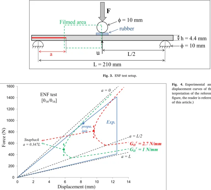
Inapreviousstudy[33],similarresultswereobtainedwithaPEEK resinandaUDcarbonlaminateusingtheunstablecharacteroftheENF test.Forlowvaluesoftheinitialcracklength,theENFtestrevealsan unstablepropagationduetothesnapbackeffect(Fig.4)[34].Onthis subject,thestandardadvisesagainstusingacracklengthshorterthan
0.347L(whereListhebeamlength,Fig.3).However,iftheobjectiveis topromoteunstablepropagation,itisinterestingtoforgetthisrule.The otherdrawbackofunstablepropagationistheimpossibilitytousethe classicaltheoryofENFteststoobtaintheinterlaminarFT.Therefore,in thiswork,IRTwasusedtoobtaintheGIIcduringunstablepropagation
[35–37].TheresultsshowanR-curveeffectattheinitialcrackgrowth
withGIIc increasingfromabout1to2.7N/mm,andconstantvalues
ofGIIcbetween0.75and1.3N/mmduringtheunstablepropagation
(Fig.2).TheproblemofusingtheIRTapproachtomeasuretheFTis thelackofconfirmationofthismethodand,inparticular,thedifficulty ofevaluatingtheTaylor–Quinneyratio:theratiobetweenthetotal en-ergydissipatedbythedamagemechanismandtheenergydissipatedas heat.Itliesbetween100%(whenalltheenergyreleasedisdissipated asheat)and0%(whenalltheenergyreleasedisstoredinthematerial). Forpolymermaterials,thisvaluevariesconsiderably,dependingonthe typeofmaterialandthetypeofloading.Forbrittlefailures,theTaylor– Quinneyratioiscloseto100%,anditliesbetween90and100%ina moregeneralcase.
Theobjectiveofthisarticleistoassesstheinfluenceofthedecrease oftheFTinmodeIIbetweenslowandfastcrackgrowth,ontheimpact behaviour,usingafiniteelement(FE)model.First,abehaviourlawof theGIIctakingthestrainrateeffectintoaccountusingtheENFtestis
determined.Second,amodelofthestrainrateeffectisproposedand evaluatedusingtheENFtest.Eventually,thismodelisusedinorder tosimulateimpacttestsperformedatdifferentenergylevelsandwith differentstackingsequences.Thestrainrateeffectishighlightedin or-dertoshowitscrucialeffectonthedamagedevelopingduringimpact and,inparticular,onthedelaminatedarea.Additionally,acomparison withanimpactmodelofthermosetcompositeisperformedinorderto compareathermoplasticandathermosetcompositelaminate. 2. ENFtest
2.1. FiniteelementmodeloftheENFtest
Thecompositelaminateusedinthisstudywasthesameastheone assessedinthepreviousworkdealingwiththemeasurementoftheFT usingIRT[33]:aUDprepreglaminatewithPEEKthermoplasticresin
Table1
Mechanicalpropertiesofcarbon/PEEKUDply[46–48]andmaterialparameters oftheDPM.
Tensile Young’s modulus in fibre direction, E lt 150 GPa
Compressive Young’s modulus in fibre direction, E lc 130 GPa
Young’s modulus in transverse direction, E t 9 GPa
In-plane shear modulus, G lt 5 GPa
Poisson’s ratio, 𝜐lt 0.3
Tensile failure strain in fibre direction, 𝜎lt 0.019
Compressive failure strain in fibre direction, 𝜎lc − 0.01
Tensile failure stress in transverse direction, 𝜎tt 84 MPa
Compressive failure stress in transverse direction, 𝜎tc − 150 MPa
In-plane shear failure stress, 𝜏ltr 160 MPa
Interlaminar fracture toughness in mode I , G Ic 1 N/mm
Interlaminar low speed fracture toughness in mode II , G II0 2.7 N/mm
Interlaminar high speed fracture toughness in mode II , G II1 1 N/mm
Reference shear velocity, Δv 0 1000 mm/s
Material parameter driving the decrease of the FT, n 0 10
Tensile fracture toughness in fibre direction, G If,t 80 N/mm
Compressive fracture toughness in fibre direction, G If,c 30 N/mm
Density, 𝜌 1600 kg.m −3
andIM7carbonfibre.Themechanicalpropertiesandthematerial pa-rametersoftheproposedFEmodelarenotedinTable1.Thegeometry oftheENFtestisgiveninFig.3.Thestackingsequenceis[016/016],
wherethe“/” atmid-thicknesscorrespondstotheTeflonfilminserted toinitiatethecrack.Differentinitialcracklengthswerestudiedbut,for thepresentwork,onlytheENFtestwithaninitialcracklengthofa0=
34mmispresented.TheENFtestisnotdetailedinthisarticlebutall thedetailscanbefoundinthepreviouspublication[33].
Theforce-displacementcurvesobtainedexperimentallyand analyti-cally,fortheENFtestwiththeinitialcracklengthof34mmareplotted inFig.4.
Thisfigureshows:
• theexperimentalcurveasasolidbluelineandthepointofinitiation ofthepropagationasabluepoint.Thecrackpropagationstartsat about1N/mmofFT,thenstablepropagationwithanR-curveeffect isobserveduptoabout2.7N/mmofFT,andunstablecrackgrowth is obtained.Itis notpossible tousethestandardtoevaluatethe FTduringthisunstablecrackpropagation,sotheFTwasevaluated usingIRT[33]atabout1N/mm(Fig.2).
• the elastic force-displacement curve of the beam without crack (a=0),withahalfbeamlength(a=L/2)andafullbeamlength (a=L)crackasdashedblacklines.Thelongerthecrack,thesmaller
Fig.3.ENFtestsetup.
Fig. 4. Experimental and analytical force-displacementcurvesoftheENFtest.(For in-terpretationofthereferencestocolourinthis figure,thereaderisreferredtothewebversion ofthisarticle.)
thestiffness.Thesecurveswereobtainedusingananalyticalmodel andaregivenforinformation.
• thecurvesoftheconditionofcrackgrowthstabilityobtained ana-lyticallyusingbeamtheory[38–40](greendashedlinefor1N/mm andreddashedlinefor2.7N/mm).Theanalyticalexpressionofthe conditionof crackgrowthstabilityis differentfor acrack length higherandlowerthanhalfthelengthofthespecimen.Thisexplains theangularpointfora=L/2.Thesnapbackphenomenonisclearly visibleforacracklengthshorterthan0.347L.
TheFEmodeloftheENFtestwasbuiltwith4volelementsinthe thicknessofthebeam,inordertohave2elementsinthethicknessof eacharm,andonecohesivezoneelementatmid-thickness(bottomright ofFig.5).Themodelwasdevelopedwiththeassumptionofaplane straininthe(x,y)plane.Therefore,onlyonevolumeelementwasused inthezdirection.Thethreecylindersof theENFtests (Fig.3)were simulatedusingrigidsurfacesandtherubberwasnotmodelled.Inthe experiment,therubberwasusedtoavoidcompressivefibrefailurejust underthecentralcylinder,butintheFEmodel,evenifafibrefailure model(detailedinIII.1)wasused,nofibredamagewasobtained.The modelwasbuiltusingAbaqusExplicitv6.13andthedisplacementof thecylinderswassetataconstantvelocity.Avalueof130mm/swas selectedafterhavingverifiedthatthetestcouldbe consideredstatic, andthatadecreaseofthisvaluedidnotaffecttheresult.Interface ele-mentswereusedtosimulatethedelaminationatmid-thicknessandthe
non-penetrationofthearmswasimposedafterthetotaldamageofthe interfaceelements.Acoupleddamagecriterionwasprogrammedwith linearcouplingbetweenshearingmode(modesIIandIII)andopening mode (modeI).However,fortheENFtestpresented here,thecrack propagatesinpuremodeII.ThemostimportantparameterfortheENF testistheFTinmodeII,GIIc,andthestrainrateeffectisofparticular
importance.Duringstablepropagation,GIIcpresentsaclassicalR-curve
effect(Fig.2).ThisR-curveeffectisduetothecreationofareal frac-tureprocesszone(FPZ)atthecracktip.However,atthebeginningof thetest,thereisapre-existingcrackgeneratedbyaTeflonfilmplaced inthemiddleplaneduringthemanufacturingprocess.Therefore,the FPZisnotarealone.Thisphenomenonisdifficulttosimulatebutis partlytakenintoaccountbytheinitialdamagingoftheinterface ele-mentsatthecracktip.Thefirstcohesiveelementatthecracktipwill quicklyreachahighstressvalueduetothehighstressconcentration. Therefore,oncethedamageis“activated”,thestiffnessoftheelement isprogressivelyreduced(III.1)and,asfortheexperimentalFPZ,stress isrelievedlocally.
Inthisstudy,forbothcrackgrowthinitiationandstablepropagation, aconstantvalueofFTof2.7N/mmisused(Figs.2and6).
2.2. Strainrateeffect
Duringtheunstablecrackgrowth,alowvalueofFTof1N/mmis observed(Figs.2and6).Itisthennecessarytodrawthepathbetween
Fig.5. ModeloftheENFtestjustbeforeandjustaftertheunstablecrackgrowth.(Forinterpretationofthereferencestocolourinthisfigure,thereaderisreferred tothewebversionofthisarticle.)
Fig.6. StrainrateeffectontheshearingFT. (Forinterpretationofthereferencestocolour inthisfigure,thereaderisreferredtotheweb versionofthisarticle.)
these2values(2.7N/mmand1N/mm)using avelocityparameter. Onewaycouldbetousethecrackgrowthvelocity.Inthepresentcase, thisvelocitywasmeasuredbetweenabout600and1000m/s,which approximatelycorrespondstotheclassicalRayleighwavespeed[41]. However,itisdifficulttousethisvelocitybecauseitsdeterminationis al-mostimpossiblewithinaninterfaceelement.Moreover,itcallsfor com-municationbetweenelements,whichistrickyintheclassicFEcodes. Therefore,thevelocitygapbetweenthetwosuperimposednodesofthe interfaceelementsisused:
Δ𝒗=𝒗𝒖𝒖𝒑𝒑𝒆𝒓−𝒗𝒖𝒍𝒐𝒘𝒆𝒓 (1)
wherevulower (vuupper)isthevelocityofthelower(upper)nodeofthe
interfaceelementintheudirection,anduisthein-planedirectionof theinterfaceelement(Fig.5).
WeproposethatthedecreaseoftheFTbetweenthelowspeedvalue andthehighspeedvaluemaybedrivenusinganexponentialfunction (Fig.6):
𝑮𝑰𝑰𝒄=𝑮𝑰𝑰1+(𝑮𝑰𝑰0−𝑮𝑰𝑰1)(1+|Δ𝒗Δ𝒗|
0
)𝒏0
(2) whereGII0isthevalueofshearingFTforstablepropagation,GII1isthe
valueofshearingFTforunstablepropagation,Δvistheshearvelocity oftheinterfaceelement,Δv0isthereferenceshearvelocity,andn0is
amaterialparameterdrivingthedecreaseoftheFT(Table1).Two pa-rametersarethenneededtodrivetheevolutionoftheFT:thereference shearvelocity,Δv0,andtheexponent,n0.Tosimplifythemodel,the
ex-ponentissetto10,whichishighenoughtoobtainarelativelyquick decreasebutlowenoughnottotriggernumericalinstabilitiesintheFE
Fig.7. Effectofthereferenceshearvelocity ontheshearvelocity(a)andonthesizeof thezoneofhighdissipatedenergy(b).(For interpretationofthereferencestocolourin thisfigure,thereaderisreferredtotheweb versionofthisarticle.)
model.Complementaryworkwasdoneinordertoevaluatetheeffectof thisparameter.Resultsshowedthatitseffectwasnegligibleifthevalue remainedlowenough.Theonlyparameterremainingtobeevaluated wasthereferenceshearvelocity.Manyvaluesweretestedbutonlythe effectofthreevalues:102,103,and104mm/sispresentedinthisarticle
(Fig.6).
InordertoevaluatethemostrelevantvalueforΔv0,itseffectonthe
force-displacementcurvewasstudied.TheinfluenceofΔv0appeared negligibleandthereforethesecurveshavenotbeenplottedonFig.9 be-causetheresultwouldnotbe readable.These 3curves areincluded betweentheblackcurve“Num.(strainrateeffect)” andthegreycurve “Num.(GIIc=2.7N/mm)”.Theunstablecrackgrowthistriggeredwhen theenergyreleaserate(ERR)reaches2.7N/mm,anditsdecreaseto 1N/mmonlyinfluencestheunstablepropagation.Theunstable propa-gationisrepresentedintheforce-displacementcurveonlybythesudden loaddrop;nodifferencecanbedetected.
AnotherevaluationofthemostrelevantvalueofΔv0couldusethe crackgrowthvelocity.Onceagain,there isnosignificant effect.The crackgrowthvelocityisrelativelyindependentof Δv0 andis always
equaltoabout1300m/s.
TodetermineΔv0,onecouldalsomeasuretheexperimentalshear
velocityduringtheENFtest.Thismeasurementisdifficulttomakeand wasnotperformedduringthiswork.Inthefuture,itwouldbe inter-estingtoconfrontthisexperimentalvaluewiththeoneselectedinthis article.Theshearvelocityduringthecrackpropagationwiththe3 val-uesofthereferenceshearvelocityΔv0(102,103and104mm/s)is
dis-playedinFig.7a.Itshouldbenotedthattheshearvelocityinagiven interfaceelementchangesbetweenthestartandtheendofthedamage. Theshearvelocityatthedamageonsetislowbecausetheinterface ele-mentstiffnessremainshigh,andishighatthedamageendbecausethe interfaceelementstiffnessbecomesnull.Therefore,wesuggestthatthe representativeshearvelocityisreachedwhenhalfoftheFTisdissipated. ForΔv0of102mm/sand103mm/s,asuddenincreaseoftheshear
velocityisobservedwhen:
Δ𝒗=Δ𝒗0 (3)
while,forΔv0equalto104 mm/sthisconditionisnever reached,so
thispeakisnotobserved.Nevertheless,thissuddenincreaseoftheshear velocitydoesnotreallyaffecttheunstablepropagationandforthethree cases, unstablecrackgrowthistriggered foracracklength ofabout 35mm.
Aninterestingaspectofthisshearvelocitypeakisthe correspond-ing decrease of theFT (Fig.7b). The higher theshear velocity, the lowertheFT.Thetippingpointisthereferenceshearvelocity(Fig.6). Consecutively,azoneofhighdissipatedenergyappearsatthe begin-ningofthecrackgrowth.ThehigherΔv0is,thelargeristhehigh
dis-sipatedenergyzone. Itisabout4, 8and155 mmwhenΔv0 is 102,
103and104mm/srespectively(Fig.7b).Thisparametercantherefore
beusedtodiscriminatethemostrelevantvalueofthereferenceshear velocity.
Todothis,theinformationgivenbytheIRTmeasurementwasused. InFig.8,thetemperaturefieldis displayedatfourtimeincrements:
Fig.8. TemperaturefieldmeasurementusingIRT dur-ingtheENFtest(1snapshotevery2ms).(For inter-pretationofthereferencestocolourinthisfigure,the readerisreferredtothewebversionofthisarticle.)
twoframesbeforetheunstablepropagationandtwoafter(onesnapshot every0.002s).Ontheframejustaftertheunstablecrackgrowth(frame 3861),azoneofhigherdissipatedenergy,ofabout10mm,isclearly visibleinthezonewherethecrackgrowthstarted.Thesizeofthiszone canthenbecomparedtothesizeofthehighdissipatedenergyzone obtainednumerically(Fig.7b)andestablishesthemostrelevantvalue forΔv0 at 103 mm/s. Moreprecisely,thevalueis between 103 and
104mm/sbutaperfectlyaccuratevalueisnotfundamental.Areference
shearvelocityof103mm/swasconsideredrelevantenoughtobeused
withconfidence.Thisvaluewillbeusedinthenextsectiontosimulate theimpacttests.
Thenumericalcurveobtainedusingthemodelwiththestrainrate effectisdisplayedasacontinuousblackcurveinFig.9.Unstablecrack growthisobtainedforacylinderdisplacementofabout13mm.The de-formedFEmodelisshownjustbeforeandjustafterthisunstablecrack growthinFig.5.TheVonMisesstressisusedasastress mathemati-calnormratherthanafailurecriterionhere.Theunstablepropagation inducesamarkedoscillationofthebeamgoingoccurringduringthe unloadingphase.
Thenumericalcurveobtainedfromthemodelwithoutthestrainrate effectisdisplayedasacontinuoussolidgreycurveforFTvaluesof1and 2.7N/mm.Unstablecrackgrowthsareobtainedfordisplacementsof about8and13mmforFTvaluesof1and2.7N/mm,respectively.These unstablepropagationsinducemarkedoscillationsofthebeamoccuring duringtheunloadingphase.Suchnumericalissueswouldneedtobe corrected in thefuturebyimprovingthemodelling ofthestructural damping.
3. Impacttest
NowthatthestrainrateeffecthasbeenidentifiedusingtheENFtest, themodelcanbeusedtosimulateimpactonplateswiththesame car-bon/PEEKcompositeandwithvariousstackingsequences.Themodel usedistheDiscretePlyModel(DPM)whichhasbeenindevelopment formorethan10yearsattheInstitutClémentAder[42–45].Detailsare availableinourpreviousarticle[33],soonlythemaincharacteristics willberecalled.
Fig.9. Experimental,analyticalandnumericalforce-displacementcurvesoftheENFtest.(Forinterpretationofthereferencestocolourinthisfigure,thereaderis referredtothewebversionofthisarticle.)
Fig.10. DPMconceptanditsassociatedspecificmesh[44].
Fig.11. Impacttestsetup[15].
3.1. DiscretePlyModel
TheprincipleoftheDPMis touseinterface elementstosimulate thediscontinuityofthematrixcracks(Fig.10).Theseelementsmake itpossibleboth tosimulate thesignificantopeningsof theplies due tomatrixcrackingandtoaccountforthecouplingbetweenthematrix
crackingandtheinterlaminardamage(delamination).Thebehaviour lawoftheseinterfacesisbasedonadoublecriterion:
• AHashin’scriterion inneighbouringvolume elements;whenthis criterionisreached,theinterfaceelementisimmediatelybroken,
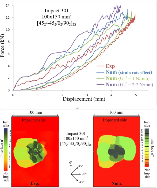
Fig.12. Experimentalandnumericalcomparisonofimpacttestofthe45° plate:force-displacementcurve(a)anddelaminatedinterfaces(b).(Forinterpretationof thereferencestocolourinthisfigure,thereaderisreferredtothewebversionofthisarticle.)
• Anenergydissipationintheinterfaceelement,drivenbythefracture toughness,alinearcouplingbetweenthemodesIandII/IIIanda lineardecreaseofthestressversusthedisplacement.Inthisinterface element,duetotheabsenceofrelevantdataontheFT,thevalues measuredintheinterlaminarinterfaceareused(Table1)andthe strainrateeffectisnotused.
Extrainterfaceelementsareusedtosimulatetheinterlaminar dam-age.Theseinterfaceelementsareofcourse,theonesmentionedin Sec-tionII,concerning theENFtest.Thestrainrateeffectisusedandits effectwillbedetailed.
Fibredamageisalsotakenintoaccountbyusingcontinuumdamage mechanicsinthevolumeelementswithadamagecriterion basedon
asimplelongitudinalstraincriteriononsetandanenergydissipation basedontheFToffibrefailure[33].
3.2. Impactmodel
Impacttests were performedon the carbon/PEEKlaminate men-tionedabove,withfourdifferentstackingsequencesof32pliesanda totalthicknessof4.51mm:
• [452,−452,02,902]2S:referredtoasthe45° stackingsequence,
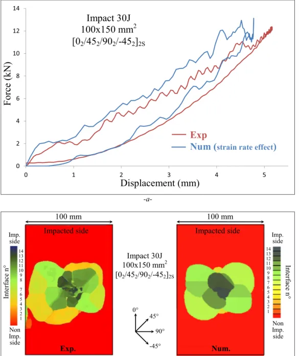
• [02,452,902,−452]2S:referredtoasthe0° stackingsequence,
Fig.13. Experimentalandnumericalcomparisonofimpacttestofthe0° plate:force-displacementcurve(a)anddelaminatedinterfaces(b).(Forinterpretationof thereferencestocolourinthisfigure,thereaderisreferredtothewebversionofthisarticle.)
• [902,−452,02,452]2S:referredtoasthe90° stackingsequence(0° stackingsequencewitha90° rotation).
Theimpactset-upwasstandardizedaccordingtotheAITM1–0010 (Fig.11).Animpactorof2.03kgwasusedandtheinitialvelocitywas setsoastoobtainimpactenergiesof10,20and30J.Thisarticlemainly focusesontheresultsobtainedwiththe30Jimpact.
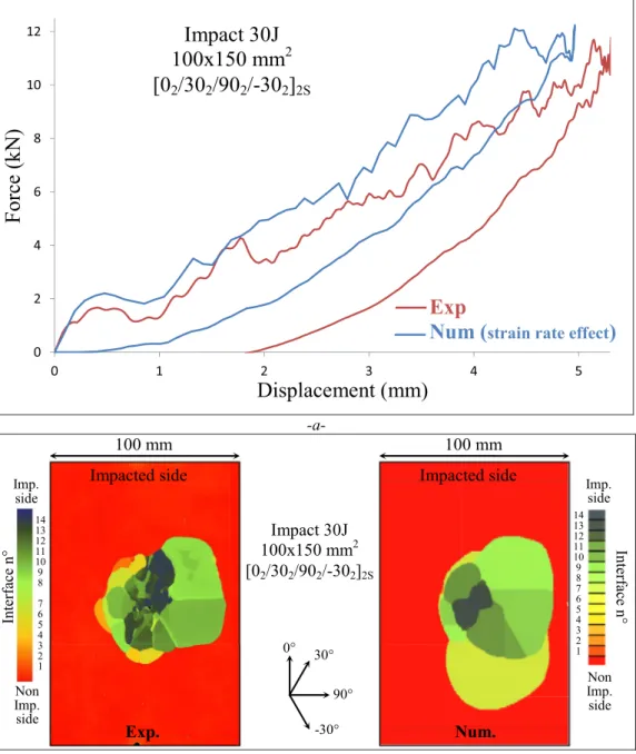
Theforce-displacementcurvesobtainedexperimentallyand numer-icallyareplottedinFigs.12a,13a,14aand15aforthe45°,0°,30° and 90° plates,respectively. Forthe45° plate,thecurves obtained with-out strain rateeffect andwiththe highspeed andlow speedFT of 1and2.7N/mm(Fig.12a),arealsoplotted.Forallcases,the corre-lationbetweentheexperimentalimpactandthecorrespondingmodel isgood.However,thenumericalresultsexhibitahigherstiffnessthan theassociatedexperimentalcurves.Thismaybedueeithertothe non-linearityoftheelasticstiffnesswhichisnottakenintoaccount,orto
anunderestimationofthedamageinthethicknessoftheplatesince, withtheDPM,thedamageintheout-of-planedirectionisnot consid-eredbecauseitisclassicallyveryweakcomparedtothein-plane dam-age.However,thisdamagecouldaddanadditionaldisplacement.The higherstiffnessofthemodelalsogeneratesalowermaximum displace-ment.Thetestisdrivenbyimpactenergy.Therefore,iftheforceis over-estimated,thedisplacementisunderestimated. Inthesameway, the energydissipated,correspondingtotheareaoftheforce-displacement curve,isoverestimatedbythemodel(about9Jfortheexperimentsand 11.5Jforthemodel).Thehigherstiffnessofthemodelshouldpartly ex-plainthisdiscrepancy.Globally,modelpredictionsareconsideredgood enoughforfurtherstudyofthestrainrateeffectoftheinterlaminarFTin modeII.
Thedelaminatedsurfacesfromtheexperiment(obtainedbyC-scan) andfromtheFEmodelaredisplayedinFigs.12b,13b,14band15b.The C-scanisclassicallyshownwithathicknessindicatormakingitpossible
Fig.14. Experimentalandnumericalcomparisonofimpacttestofthe30° plate:force-displacementcurve(a)anddelaminatedinterfaces(b).(Forinterpretationof thereferencestocolourinthisfigure,thereaderisreferredtothewebversionofthisarticle.)
toevaluatethepositionsofthedelaminatedinterfaces.Theinterface numbermaynotbe perfectlyaccuratebecauseitwassometimes dif-ficulttoseparatetwocloseinterfacesandtheultrasonicinvestigation involvedsomeuncertainty.Onecandistinguishthedouble-plyat mid-thickness.Tocomparethemodelwiththeexperiment,thedelaminated interfaceswerecolouredwiththesamecoloursastheC-scan.Thered colourcorrespondstopristineareas.DuetheuncertaintyoftheC-scan procedure,theremaybesome misinterpretationinthecolourofthe delaminatedinterfaceobtainednumerically.Onaverage,thisapproach providesarapidwaytocomparethedelaminatedinterfaces. Compar-isonsbetweenC-scanandDPMaresatisfactoryoverallbutdiscrepancies canbefound.Forthe45° plate(Fig.12b),thethreedelaminated inter-facesattheleft ofthepicturearewellreproducedbythemodelbut thedelaminatedinterfaceobtainednumericallyattheright,isclearly overestimated.Severaldelaminatedinterfaces nearthenon-impacted sidee.g.theinterfaces2,3and4forthe0° and90° plates,seemtobe underestimatedbythemodel.Thisdiscrepancycouldbedueto
under-estimationof thefibrefailure.Whenthereisasmallamountoffibre failure,thedelaminatedinterfacesaremostlythemid-thicknessones, duethehighshearinthiszone.However,whenthefibrefailure devel-opsfurther,theinterfaceslocatednearthenon-impactedsidetendto delaminate.Togiveabetterideaoftheextentofthepredictedfibre damage,thetopleftpartofFig.16showsthefibredamageobtained afterimpactonthe45° plate.Thebluecolourmeansnofibredamage andtheredmeanstotalfibredamage(atthetopright,thefibredamage correspondstotheimpactmodelwithoutthestrainrateeffectand,at thebottom,toanimpactonacarbon/epoxyplate).Itisclearthatthere isaverysmallamountoffibredamageandthedelaminatedinterfaces atmid-thicknessareclearlyvisible.
Anotherimportantfeatureistheunsymmetricalshapeofthe delam-inatedsurface.Fromaglobalpointofview,thisasymmetryis repro-ducednumericallyevenifthemodelisperfectlysymmetrical.TheFE modelsareindeedtotallysymmetrical(centralsymmetry),whichis,of course,notthecasefortheexperiments.Duringtheexperiments,even
Fig.15. Experimentalandnumericalcomparisonofimpacttestofthe90° plate:force-displacementcurve(a)anddelaminatedinterfaces(b).(Forinterpretationof thereferencestocolourinthisfigure,thereaderisreferredtothewebversionofthisarticle.)
thoughtheplatewaspositionedwithgreatcareandtheimpactorwell guided,themarginoferrorinpositionoftheimpactorpointisestimated at±1mm.Fornumericalresults,theproblemisperfectlysymmetrical andthepositioningoftheunsymmetricalareawaschoseninorderto beconsistentwiththeexperiments,andthustomakecomparisons eas-ier.Otherresultsintheliteratureshow anasymmetryofthedamage
[49,50].Itseemsthattheasymmetryismainlyobservedwhenthe de-laminationissituatednearthemid-thickness.Inthepresentstudy,the asymmetryisoften,butnotalways,observedfor30Jimpact.Fig.17
presentsthreeC-scansof30Jimpacttestson30° plateasanexample. Thethreetestsareexactlythesame,exceptfortheuncertainties re-latedtothemanufacturingprocessandtotheexperiment.Amongthe threetests,twoareunsymmetricalandaresimilar,andoneis symmet-rical.Thisdistributionisfairlyrepresentativeofsomecampaigntests performedon similarplates. Inordertocomparethisparticular fea-turewiththeFEmodel,theimpactpointwasshifted1mmleft,right,
downorupforafewimpactmodels.Formostofthemodels,thisled tonosignificantdifferencewiththeperfectlycentredmodelbut,ina fewconfigurations,differenceswerefound.Forexample,Fig.18shows theresultoftheimpactmodelonthe0° platewitha1mmoffset(to theleft).Thereisasignificantdifferencewiththecentredimpactmodel (Fig.13b).Thisfeatureisrepresentativeofwhatisobserved experimen-tallyandshouldbeexplainedbytheinstabilityofthepropagationofthe delaminationsatmid-thickness.Unlikethedelaminationspropagating nearthenon-impactedside,whicharealmostsymmetricandseem sta-ble,thepropagationatmid-thicknessseemslessstable.Thispointcould alsobe relatedtothehighstrainrateeffectobserved withthis type ofimpact.Ifthedelaminationsatmid-thicknessareunstable,thenthe crackgrowthvelocitycouldbehigherthantheclassicaldelamination nearthenon-impactedsideandwouldhighlightthestrainrateeffect. Thisis,however,putforwardonlyasapossibleexplanationandwill havetobeexaminedthroughextraresearch.
Fig.16. Fibrefailureobtainednumericallyforthecarbon/PEEK45° platewiththestrainrateeffect,withthehighspeedFT,andforcarbon/epoxyplate.(For interpretationofthereferencestocolourinthisfigure,thereaderisreferredtothewebversionofthisarticle.)
Fig.17. Experimentaltestsonthe30° plate:delaminatedinterfaces.
Fig.19. EffectoftheFTonthedelaminatedinterfacesofthe45° plateimpact.
Fig.21. Numericalcomparisonofcarbon/PEEKandcarbon/epoxylaminateplateinimpacttestofthe45° plate:force-displacementcurve(a)anddelaminated interfaces(b).(Forinterpretationofthereferencestocolourinthisfigure,thereaderisreferredtothewebversionofthisarticle.)
3.3. Effectoffracturetoughness
Onaverage,thestrainrateeffectseemstobeabletoaccountforthe largedelaminatedsurfaceareaobservedduringimpact.Toconfirmthis, impactmodelswererunwiththestrainratementionedabove(leftof
Fig.19)andwithoutanystrainrateeffect,withFTsof1and2.7N/mm (rightofFig.19).Ontheonehand,itisclearthatthedamagesimulated withtheFTmeasuredatlowspeed(2.7N/mm)stronglyunderestimated thedelaminatedarea.Ithastobenotedthatthisvalueof2.7N/mmis thestandardvalue(determinedusingindustrialnorms).This configura-tionalsoexhibitstoomuchfibredamageonthetwofirstpliessituated neartheimpactedside.
Thisfibrefailureisvisibleduethedelaminationoftheinterfaces13 and14(Fig.19).Thisgreaterfibredamageisconfirmedbycomparing thefibredamagevariablewiththestrainrateeffect(topleftofFig.16) andforthehighervalueoftheFT(toprightofFig.16).Thefibredamage
withthelowvalueofFTisnotrepresentedbecauseitissimilartothe oneobservedwiththestrainrateeffect.
Ontheotherhand,theglobalshapeofthedelaminatedinterfaces obtainedwith1N/mmoffractureisrelativelysimilartothatobtained withthestrainrateeffect.Thisislogicalbecause,oncethecrackgrowth starts, the FTdecreases quickly tothis value due tothe strain rate (Fig.6).Onlythedelaminationoftheinterfacesneartheimpactedside (interfaces12,13and14)ismodifiedbetweenthelowvalueofFTand thestrainrateeffect.
Inordertoenrichthecomparisonbetweentheexperimentandthe DPM,impacttestsat10Jand20Jwereperformedandnumerically simulatedonthe45° plate(Fig.20).Globally,theincreaseofthe delami-natedsurfacewiththeimpactenergylevelistakenintoaccountmoreor lesswellbythemodelusingthestrainrateeffect.Again,thefibrefailure ofthefirstplylocatedontheimpactedsideseemsunderestimated.Its failureisclearlyobservedinthe20Jimpactbythecleardelamination
Table2
Mechanicalpropertiesofcarbon/epoxyUDplyusedasparametersoftheDPM. Tensile Young’s modulus in fibre direction, E lt 130 GPa
Compressive Young’s modulus in fibre direction, E lc 100 GPa
Young’s modulus in transverse direction, E t 7.7 GPa
In-plane shear modulus, G lt 4.75 GPa
Poisson’s ratio, ϑlt 0.3
Tensile failure strain in fibre direction, 𝜀 lt 0.018
Compressive failure strain in fibre direction, 𝜀 lc − 0.0125
Tensile failure stress in transverse direction, 𝜎tt 60 MPa
Compressive failure stress in transverse direction, 𝜎tc − 250 MPa
In-plane shear failure stress, 𝜏ltr 110 MPa
Interlaminar fracture toughness in mode I , G Ic 0.5 N/mm
Interlaminar fracture toughness in mode II , G IIc 1.6 N/mm
Tensile fracture toughness in fibre direction, G If,t 100 N/mm
Compressive fracture toughness in fibre direction, G If,c 30 N/mm
Density, 𝜌 1600 kg.m −3
ofinterface14(Fig.20b).Itcanbenotedthatthedelaminatedsurface areameasuredduringthe20Jimpactissymmetricalwiththecentral pointoftheplate,unlikethedelaminatedsurfaceobservedinthe30J impact(Fig.12b).Fromexperimentalandnumericalobservations,the asymmetryofthedelaminatedsurfaceseemstoappearbetween20and 30J.Nevertheless,theasymmetryissometimesnotobtainedwiththe experiment,evenat30J.
3.4. Comparisonwiththermosetcomposite
Inordertocomparethethermoplasticresinwithathermosetresin, aconfigurationwith acarbon/epoxyplatewasmodelledfor the45° plateimpact.Onlythesimulationwasrun,andthematerialparameters weretakenfrompreviousstudies(Table2).Severalexperimentshave alreadybeenperformedwiththesematerialparameters[42,43,45,50]
andtheauthorshaverelativelyhighconfidenceintheassociatedresult. NostrainrateeffectwasusedforthissimulationbecausetheFTinmode IIdoesnotseemtovarysignificantlyforepoxyresin.Moreexactly,the resultsfoundintheliterature[51,52]andinourexperimentsdonot evidenceastrainrateeffectforModeII,unlikeintheworkofFriedrich etal.[13], whomeasuredastrainrateeffectforepoxyresinsimilar tothatforPEEK resin.Thebehaviourdifferencemaycomefromthe differenttypesofepoxypolymerresinsused,butthisquestionremains openatthisstage.
Thecarbon/epoxyplateexhibitsaslightlysmallersizeof delami-nationthanthecarbon/PEEKplateinFig.21b.Thislowersizeof de-laminationforepoxy resinisdue tothehighervalueof FTin mode
II,1.6N/mm,comparedtothehighspeedvalueofFTforPEEKresin, 1 N/mm. An asymmetry of the delaminated interfaces of the car-bon/epoxyplatecanalsobeobserved(rightofFig.21b),especiallyin theonessituatedinthelowerpartofthethickness(interfaces3–5).
Theforce-displacementcurveofthecarbon/epoxyplateissimilar tothatofthecarbon/PEEK(Fig.21a).Thefibrefailurepatternisalso relativelyclosetothecarbon/PEEKone(Fig.16).Thedamageis actu-allylargerthantheonesimulatedwiththestrainrateeffectandslightly smallerthantheonesimulatedwiththehighvalueofFT.Itshouldbe noted(Fig.21b)thatthepatternshownwasrecordedattheendofthe impacttest,whentheloadhasreturnedtozero.Therefore,thepattern isrepresentativeofthedeformationoftheplateobtainedstraightafter impact.Theresidualindentationisslightlyreducedbyarelaxation phe-nomenonnotyettakenintoaccountintheDPM.Ultimately,theimpact behaviourofthecarbon/epoxyplateisrelativelysimilartotheimpact behaviourofthecarbon/PEEK,despitethehigherstaticvalueofFTfor PEEKresin.
Toconclude,eventhoughtheFTinmodeII(ormoreexactlythelow speedvalueoftheFT)ishigherforPEEKresinthanforepoxyresin,the delaminatedsurfaceislargerforPEEKresin.Thisisduetothestrain rateeffect,whichconsiderablyreducestheFT.Thisdecreaseisclearly aproblemforPEEKcompositelaminatesbecauseitlimitstheinterestof
thesematerialsforimpactdamagetolerance.Nevertheless,thisfeature needstobeconfirmedbyotherstudiesandwithotherthermoplastic resins.Inparticular,otherstackingsequencescouldleadtodifferent conclusions asthestackingsequencesusedinthis studyalways con-tainedtwoconsecutivepliesinthesamedirection,whichisknownto increasethedevelopmentofthedelaminatedarea.
4. Conclusion
AmodeltakingthestrainrateeffectoftheFTinmodeIIof inter-laminarinterfacesintoaccounthasbeendeveloped.Thefirstpartofthis researchwastoidentifythecorrectparametersusinganENFtest espe-ciallyset-uptogenerateunstablecrackgrowth.Processingtheresults madeitpossibletoexperimentallymeasurethevalueofFTinmodeII forhighspeedpropagationandtoidentifythestrainratebehaviourto beimplementedinthemodel.
Thesecondpartconsistedofsimulatingimpacttestswithdifferent stackingsequencesanddifferentimpactenergylevelswiththehelpof the DPMtaking thestrainrate effectinto account.TheDPM exhib-ited relativelygoodcorrelationswithexperiment.Itmadeitpossible toidentifysomeasymmetryofthedelaminatedinterfaces andto ob-servethecommonpropagationofgroupsofinterfacessituatednearthe mid-thicknessofthelaminatedplates.
Finally,theimpactdamageinthecarbon/PEEKofthis studywas comparedwiththatofclassicalcarbon/epoxyplateswiththehelpof numericalsimulations(DPM).Itshowedthat,whenthelowervalueof FTinmodeIIofPEEKresinwasusedforhighspeedpropagation,larger delaminatedareasweregenerated;contrarytotheresultexpectedwhen consideringthehigherFTofPEEKforlowspeedcrackgrowth.
Thisresultconfirmedtheconclusionsdrawninourpreviousstudy focusedonthemeasurementofFTinmodeIIusingtheENFtestandIRT technique[33].Italsoquestionstheinterestofcarbon/PEEKlaminate compositescomparedtocarbon/epoxylaminatecompositesintermsof impactdamagetoleranceproperties.Itwouldbeinterestinginthefuture toconfronttheresultsofthisresearchwithotherstudiesondifferent fibre/matrix combinationsandstackingsequencesandtopursuethe researchonthenumericalmodellingonthecompressionafterimpact behaviour.
DeclarationofCompetingInterest
Theauthorsdeclarethattheyhavenoknowncompetingfinancial interestsorpersonalrelationshipsthatcouldhaveappearedtoinfluence theworkreportedinthispaper.
Acknowledgement
The authors gratefully acknowledge CALMIP (CALcul en Midi-Pyrénées,(https://www.calmip.univ-toulouse.fr)foraccesstotheHPC resourcesunderallocationp1026.
Supplementarymaterials
Supplementarymaterialassociatedwiththisarticlecanbefound,in theonlineversion,atdoi:10.1016/j.jcomc.2020.100031.
References
[1] J. Morton , E.W. Godwin , Impact response of tough carbon fibre composites, Compos. Struct. 13 (1989) 19 .
[2] D.C. Prevorsek , H.B. Chin , A. Bhatnagar , Damage tolerance: design for structural integrity and penetration, Compos. Struct. 23 (1993) 12 .
[3] D. Garcia-Gonzalez, M. Rodriguez-Millan, A. Rusinek, A. Arias, Low temperature effect on impact energy absorption capability of PEEK composites, Compos. Struct. 134 (2015) 440–449, doi: 10.1016/j.compstruct.2015.08.090 .
[4] D. Garcia-Gonzalez, A. Rusinek, T. Jankowiak, A. Arias, Mechanical impact be- havior of polyether–ether–ketone (PEEK), Compos. Struct. 124 (2015) 88–99, doi: 10.1016/j.compstruct.2014.12.061 .
[5] K. Srinivasan, W.C. Jackson, B.T. Smith, J.A. Hinkley, Characterization of damage modes in impacted thermoset and thermoplastic composites, J. Reinf. Plast. Compos. 11 (10) (1992) 1111–1126, doi: 10.1177/073168449201101004 .
[6] P. Bajurko, Comparison of damage resistance of thermoplastic and thermoset carbon fibre-reinforced composites, J. Thermoplast. Compos. Mater. (2019), doi: 10.1177/0892705719844550 .
[7] I. De Baere, S. Jacques, W. Van Paepegem, J. Degrieck, Study of the mode I and mode II interlaminar behaviour of a carbon fabric reinforced thermoplastic, Polym. Test. 31 (2) (2012) 322–332, doi: 10.1016/j.polymertesting.2011.12.009 . [8] P. Davies , M.L. Benzeggagh , The delamination behavior of carbon fiber reinforced
PPS, in: Proceedings of the 32nd International SAMPE Symposium, 1987 . [9] F. Lachaud, B. Lorrain, L. Michel, R. Barriol, Experimental and numeri-
cal study of delamination caused by local buckling of thermoplastic and thermoset composites, Compos. Sci. Technol. 58 (5) (1998) 727–733, doi: 10.1016/S0266-3538(97)00153-X .
[10] T. O’Brien , Composite interlaminar shear fracture toughness, GIIc: shear measure- ment or sheer myth?, in: R. Bucinell (Ed.) Composite Materials: Fatigue and Fracture:
7th Volume , ASTM International, West Conshohocken, PA, 1998, pp. 3–18 . [11] B. Vieille, V.M. Casado, C. Bouvet, About the impact behavior of woven-ply carbon
fiber-reinforced thermoplastic- and thermosetting-composites: a comparative study, Compos. Struct. 101 (2013) 9–21, doi: 10.1016/j.compstruct.2013.01.025 . [12] B. Vieille, V.M. Casado, C. Bouvet, Influence of matrix toughness and ductil-
ity on the compression-after-impact behavior of woven-ply thermoplastic- and thermosetting-composites: a comparative study, Compos. Struct. 110 (2014) 207– 218, doi: 10.1016/j.compstruct.2013.12.008 .
[13] K. Friedrich, R. Walter, L.A. Carlsson, A.J. Smiley, J.W. Gillespie, Mechanisms for rate effects on interlaminar fracture toughness of carbon/epoxy and carbon/PEEK composites, J. Mater. Sci. 24 (9) (1989) 3387–3398, doi: 10.1007/BF01139070 . [14] L.C.M. Barbosa, D.B. Bortoluzzi, A.C. Ancelotti, Analysis of fracture tough-
ness in mode II and fractographic study of composites based on Elium ○R
150 thermoplastic matrix, Compos. Part B Eng. 175 (2019) 107082, doi: 10.1016/j.compositesb.2019.107082 .
[15] ‘Airbus Industrie Test Method. Fiber Reinforced Plastics Determination of Compres- sion Strength After Impact. AITM-1.0010 ′ . 1994.
[16] Z. Major , R.W. Lang , Rate dependent fracture toughness of plastics, in: European Structural Integrity Society, 32, Elsevier, 2003, pp. 187–198 .
[17] C.R. Siviour, J.L. Jordan, High strain rate mechanics of polymers: a review, J. Dyn. Behav. Mater. 2 (1) (2016) 15–32, doi: 10.1007/s40870-016-0052-8 .
[18] D. Lee, H. Tippur, P. Bogert, Quasi-static and dynamic fracture of graphite/epoxy composites: an optical study of loading-rate effects, Compos. Part B Eng. 41 (6) (Sep. 2010) 462–474, doi: 10.1016/j.compositesb.2010.05.007 .
[19] C.A. Weeksa , C.T. Sud , Modeling non-linear rate-dependant behavior in fiber èrein- forced composites, Compos. Sci. Technol. 58 (1998) 603–611 .
[20] M. Ploeckl , Effect of Strain Rate On the Tensile, Compressive, and Shear Re- sponse of Carbon-Fiber-Reinforced Thermoplastic Composites, Technische Univer- sität München, 2018 .
[21] L. Cadieu, J.B. Kopp, J. Jumel, J. Bega, C. Froustey, Strain rate ef- fect on the mechanical properties of a glass fibre reinforced acrylic ma- trix laminate. An experimental approach, Compos. Struct. 223 (2019) 110952, doi: 10.1016/j.compstruct.2019.110952 .
[22] H. Wafai, et al., In situ micro-scale high-speed imaging for evaluation of fracture propagation and fracture toughness of thermoplastic laminates subjected to impact, Compos. Struct. 210 (2019) 747–754, doi: 10.1016/j.compstruct.2018.11.092 . [23] V.L. Reis et al., ‘High Strain-Rate Behavior of Fiber-Reinforced
Thermoplastic Composites Under Compressive Loadings’, 2017, doi: 10.26678/ABCM.COBEM2017.COB17-1122 .
[24] S. Hashemi , A.J. Kinloch , J.G. Williams , The effects of geometry, rate and tempera- ture on the mode I, mode II and mixed-mode I/II interlaminar fracture of carbon-fi- bre/poly(ether-ether ketone) composites, J. Compos. Mater. 24 (1990) 39 . [25] M. Blyton , The Interlaminar Fracture of Composite Materials, University of Liver-
pool, 1999 .
[26] P. Compston , The e €ect of matrix toughness and loading rate on the mode-II inter- laminar fracture toughness of glass- ○Rbre/vinyl-ester composites, Compos. Sci. Tech-
nol. (2001) 13 .
[27] B.L.K. Blackman, ‘The failure of fibre composites and adhesively bonded fibre com- posites under high rates of test’, J. Mater. Sci., p. 16.
[28] W.J. Cantwell, M. Blyton, Influence of loading rate on the interlaminar fracture prop- erties of high performance composites - a review, Appl. Mech. Rev. 52 (6) (Jun. 1999) 199–212, doi: 10.1115/1.3098934 .
[29] A.J. Smiley , R.B. Pipes , Rate sensitivity of mode II interlaminar fracture toughness in graphite/epoxy and graphite/PEEK composite materials, Compos. Sci. Technol. 29 (1987) 15 .
[30] S. Hamdan, G.M. Swallowe, Crystallinity in PEEK and PEK after mechani- cal testing and its dependence on strain rate and temperature, J. Polym. Sci. Part B Polym. Phys. 34 (4) (1996) 699–705 AID-POLB10>3.0.CO;2-C, doi: 10.1002/(SICI)1099-0488(199603)34:4 < 699 .
[31] Z. El-Qoubaa, R. Othman, Tensile behavior of polyetheretherketone over a wide range of strain rates, Int. J. Polym. Sci. 2015 (2015) 1–9, doi: 10.1155/2015/275937 . [32] S. Mall, G.E. Law, M. Katouzian, Loading rate effect on interlaminar fracture tough- ness of a thermoplastic composite, J. Compos. Mater. 21 (6) (Jun. 1987) 569–579, doi: 10.1177/002199838702100607 .
[33] P. Garcia Perez, C. Bouvet, A. Chettah, F. Dau, L. Ballere, P. Pérès, Ef- fect of unstable crack growth on mode II interlaminar fracture toughness of a thermoplastic PEEK composite, Eng. Fract. Mech. 205 (2019) 486–497, doi: 10.1016/j.engfracmech.2018.11.022 .
[34] C.C. Chamis, P.L.N. Murthy, L. Minnetyan, Progressive fracture of polymer matrix composite structures, Theor. Appl. Fract. Mech. 25 (1) (1996) 1–15, doi: 10.1016/0167-8442(96)00002-X .
[35] T. Lisle, C. Bouvet, M.L. Pastor, P. Margueres, R. Prieto Corral, Damage analysis and fracture toughness evaluation in a thin woven composite laminate under static tension using infrared thermography, Compos. Part A Appl. Sci. Manuf. 53 (2013) 75–87, doi: 10.1016/j.compositesa.2013.06.004 .
[36] T. Lisle, C. Bouvet, N. Hongkarnjanakul, M.-.L. Pastor, S. Rivallant, P. Margueres, Measure of fracture toughness of compressive fiber failure in composite struc- tures using infrared thermography, Compos. Sci. Technol. 112 (2015) 22–33, doi: 10.1016/j.compscitech.2015.03.005 .
[37] T. Lisle, C. Bouvet, M.L. Pastor, T. Rouault, P. Marguerès, Damage of woven com- posite under tensile and shear stress using infrared thermography and micrographic cuts, J. Mater. Sci. 50 (18) (2015) 6154–6170, doi: 10.1007/s10853-015-9173-z . [38] O. Allix, P. Ladevéze, A. Corigliano, Damage analysis of interlaminar fracture spec-
imens, Compos. Struct. 31 (1) (1995) 61–74, doi: 10.1016/0263-8223(95)00002-X . [39] P. Davies , Protocols for interlaminar fracture testing of composites, ESIS-Polymers
and Composites Task Group Presented at the, IFREMER, Centre de Brest, 1993 . [40] A.B. Pereira, A.B. de Morais, A.T. Marques, P.T. de Castro, Mode II interlaminar
fracture of carbon/epoxy multidirectional laminates, Compos. Sci. Technol. 64 (10– 11) (2004) 1653–1659, doi: 10.1016/j.compscitech.2003.12.001 .
[41] J.W.S.B. Rayleigh, ‘The Theory of Sound, vol 2.’, 1896.
[42] C. Bouvet, B. Castanié, M. Bizeul, J.-.J. Barrau, Low velocity impact modelling in laminate composite panels with discrete interface elements, Int. J. Solids Struct. 46 (14–15) (2009) 2809–2821, doi: 10.1016/j.ijsolstr.2009.03.010 .
[43] C. Bouvet, S. Rivallant, J.J. Barrau, Low velocity impact modeling in composite lami- nates capturing permanent indentation, Compos. Sci. Technol. 72 (16) (2012) 1977– 1988, doi: 10.1016/j.compscitech.2012.08.019 .
[44] S. Rivallant, C. Bouvet, N. Hongkarnjanakul, Failure analysis of CFRP lam- inates subjected to compression after impact: FE simulation using discrete interface elements, Compos. Part A Appl. Sci. Manuf. 55 (2013) 83–93, doi: 10.1016/j.compositesa.2013.08.003 .
[45] J. Serra, C. Bouvet, B. Castanié, C. Petiot, Scaling effect in notched compos- ites: the Discrete Ply Model approach, Compos. Struct. 148 (2016) 127–143, doi: 10.1016/j.compstruct.2016.03.062 .
[46] HEXCEL, ‘HexTow Carbon Fiber Datasheet’. 2014. [47] GOODFELLOW, ‘GoodFellow Peek Resin Datasheet’. 2014.
[48] F. Lemarchand , Étude De L’apparition Des Contraintes Résiduelles Dans Le Procédé D’empilement Par Soudage Et Consolidation En Continu De Composites Thermoplas- tiques, Arts et Métiers ParisTech, 2008 .
[49] F. Léonard, J. Stein, C. Soutis, P.J. Withers, The quantification of impact damage dis- tribution in composite laminates by analysis of X-ray computed tomograms, Compos. Sci. Technol. 152 (2017) 139–148, doi: 10.1016/j.compscitech.2017.08.034 . [50] N. Hongkarnjanakul, C. Bouvet, S. Rivallant, Validation of low velocity impact mod-
elling on different stacking sequences of CFRP laminates and influence of fibre fail- ure, Compos. Struct. 106 (2013) 549–559, doi: 10.1016/j.compstruct.2013.07.008 . [51] J.W. Gillespie, L.A. Carlsson, A.J. Smiley, Rate-dependent mode I interlaminar crack
growth mechanisms in graphite/epoxy and graphite/PEEK, Compos. Sci. Technol. 28 (1) (1987) 1–15, doi: 10.1016/0266-3538(87)90058-3 .
[52] I. Maillet and L. Michel, ‘Effet De La Vitesse De Chargement Sur Le Taux De Resti- tution D’énergie D’un CFRP En Mode I et II’, p. 9, 2017.
![Fig. 1. Effect of the crack growth speed on modes I and II FT for carbon/epoxy and carbon/peek composites (a) [13] , and ductile (b) and brittle behaviour (c) of delamination of PEEK resin [29] .](https://thumb-eu.123doks.com/thumbv2/123doknet/2949657.80144/3.892.168.729.84.587/effect-growth-carbon-composites-ductile-brittle-behaviour-delamination.webp)
![Fig. 2. FT in mode II versus crack growth evolution of the ENF tests [33] . (For interpretation of the references to colour in this figure, the reader is referred to the web version of this article.)](https://thumb-eu.123doks.com/thumbv2/123doknet/2949657.80144/4.892.138.758.86.393/versus-evolution-interpretation-references-figure-referred-version-article.webp)


![Fig. 11. Impact test set up [15] .](https://thumb-eu.123doks.com/thumbv2/123doknet/2949657.80144/9.892.82.816.502.744/fig-impact-test-set-up.webp)