HAL Id: tel-01344873
https://pastel.archives-ouvertes.fr/tel-01344873
Submitted on 12 Jul 2016HAL is a multi-disciplinary open access archive for the deposit and dissemination of sci-entific research documents, whether they are pub-lished or not. The documents may come from teaching and research institutions in France or abroad, or from public or private research centers.
L’archive ouverte pluridisciplinaire HAL, est destinée au dépôt et à la diffusion de documents scientifiques de niveau recherche, publiés ou non, émanant des établissements d’enseignement et de recherche français ou étrangers, des laboratoires publics ou privés.
Understanding the relationships between aesthetic
properties of shapes and geometric quantities of
free-form curves and surfaces using Machine Learning
Techniques
Aleksandar Petrov
To cite this version:
Aleksandar Petrov. Understanding the relationships between aesthetic properties of shapes and ge-ometric quantities of free-form curves and surfaces using Machine Learning Techniques. Mechanical engineering [physics.class-ph]. Ecole nationale supérieure d’arts et métiers - ENSAM, 2016. English. �NNT : 2016ENAM0007�. �tel-01344873�
N°: 2009 ENAM XXXX
Arts et Métiers ParisTech – Centre d’Aix-en-Provence, LSIS, France Università degli Studi di Genova, CNR-IMATI, Genova, Italia
2016-ENAM-0007
Director of thesis: Philippe VÉRON Co-director of thesis: Franca GIANNINI
Co-supervisors of the thesis: Jean-Philippe PERNOT, Bianca FALCIDIENO
Jury
M. Jean-François OMHOVER, Associate Professor, CPI, Arts et Méties ParisTech President M. Umberto CUGINI, Professor, KAEMaRT, Polytechnico di Milano Reviewer Mme Géraldine MORIN, Associate Professor, INP, Université de Toulouse Reviewer Mme Rezia MOLFINO, Professor, PMAR, Università degli Studi di Genova Examiner
Presented and defended publicly by
Aleksandar PETROV
January 25th, 2016
Understanding the relationships between aesthetic properties of shapes
and geometric quantities of free-form curves and surfaces using
Machine Learning Techniques
PhD THESIS
in cotutelle To obtain the degree ofDocteur de
l’Arts et Métiers ParisTech
Spécialité “Mécanique – Conception”
École doctorale n° 432: “Science des Métiers de l’ingénieur”
and
Dottore di Ricerca della
Università degli Studi di Genova
Specialità “Ingeneria Meccanica”
Scuola di Dottorato: “Scienze e tecnologie per l’ingegneria” ciclo XXVI
T
H
È
S
E
To my parents They would have been proud
EXPLOITATION DE TECHNIQUES D’APPRENTISSAGE ARTIFICIEL POUR LA
COMPREHENSION DES LIENS ENTRE LES PROPRIETES ESTHETIQUES DES FORMES ET LES GRANDEURS GEOMETRIQUES DE COURBES ET SURFACE GAUCHES
RESUME: Aujourd’hui, sur le marché, on peut trouver une vaste gamme de produits différents ou des formes variées d’un même produit et ce grand assortiment fatigue les clients. Il est clair que la décision des clients d’acheter un produit dépend de l'aspect esthétique de la forme du produit et de l’affection émotionnelle. Par conséquent, il est très important de comprendre les propriétés esthétiques et de les adopter dans la conception du produit, dès le début. L'objectif de cette thèse est de proposer un cadre générique pour la cartographie des propriétés esthétiques des formes gauches en 3D en façon d'être en mesure d’extraire des règles de classification esthétiques et des propriétés géométriques associées. L'élément clé du cadre proposé est l'application des méthodologies de l’Exploration des données (Data Mining) et des Techniques d’apprentissage automatiques (Machine Learning Techniques) dans la cartographie des propriétés esthétiques des formes. L'application du cadre est d'étudier s’il y a une opinion commune pour la planéité perçu de la part des concepteurs non-professionnels. Le but de ce cadre n'est pas seulement d’établir une structure pour repérer des propriétés esthétiques des formes gauches, mais aussi pour être utilisé comme un chemin guidé pour l’identification d’une cartographie entre les sémantiques et les formes gauches différentes. L'objectif à long terme de ce travail est de définir une méthodologie pour intégrer efficacement le concept de l’Ingénierie affective (c.à.d. Affective Engineering) dans le design industriel.
Mots clés : Courbes et surfaces gauches, techniques d'apprentissage automatiques, propriétés esthétiques, ingénierie affective, design industriel.
UNDERSTANDING THE RELATIONSHIPS BETWEEN AESTHETIC PROPERTIES OF SHAPES AND GEOMETRIC QUANTITIES OF FREE-FORM CURVES AND SURFACES USING
MACHINE LEARNING TECHNIQUES
ABSTRACT: Today on the market we can find a large variety of different products and different shapes of the same product and this great choice overwhelms the customers. It is evident that the aesthetic appearance of the product shape and its emotional affection will lead the customers to the decision for buying the product. Therefore, it is very important to understand the aesthetic proper-ties and to adopt them in the early product design phases. The objective of this thesis is to propose a generic framework for mapping aesthetic properties to 3D free-form shapes, so as to be able to extract aesthetic classification rules and associated geometric properties. The key element of the proposed framework is the application of the Data Mining (DM) methodology and Machine Learning Techniques (MLTs) in the mapping of aesthetic properties to the shapes. The application of the framework is to investigate whether there is a common judgment for the flatness perceived from non-professional designers. The aim of the framework is not only to establish a structure for mapping aesthetic properties to free-form shapes, but also to be used as a guided path for identifying a mapping between different semantics and free-form shapes. The long-term objective of this work is to define a methodology to efficiently integrate the concept of Affective Engineering in the Industrial Designing.
Keywords : Free-form curves and surfaces, machine learning techniques, aesthetic properties, affective engineering, industrial design.
7
Chapter 1
Introduction
1 Introduction
Nowadays, it is commonly admitted that the aesthetic appearance of a product has an emphasized role in its commercial success. Today, on the market, we can find a large variety of different products and different shapes of the same product and this abundance of choic-es overwhelms the customer. At the beginning, the decision for buying a product is generally based on three criteria: Functionality, Price and Quality (Figure 1.1). By giving some priority to one of these criteria we can easily decide which product we are going to buy. For in-stance, if we take the price as a main criterion, we can find many products that satisfy the functionality with an acceptable quality for the same price. In such situation, how to make a choice? Actually, the aesthetic appearance of the product plays a key role in its commercial success. Therefore, understanding and manipulating the aesthetic properties of shapes and its visual impression in the early design phases has become a very attractive field of re-search.
Figure 1.1: Reasoning about the relationships between the product shape and its properties
As a consequence, designing products with attractive shapes requires knowledge about the feelings and impression the products evoke on the customers that are also the
8 end-users. Understanding such affective influence of the product shape in the product de-sign process requires the use of appropriate methods that can extract and transform subjec-tive impressions about a product into concrete design parameters and tools, referred to as Affective Engineering (AE). AE is actually a new aspect integrated in the product design pro-cess that provides a platform where emotional features are incorporated into design appeal-ing products (Nagamachi, 2011). The final and long-term objective of the AE is to define di-rect mapping between surface shape and emotions. Giannini et al. (Giannini & Monti, A survey of tools for understending and exploiting the link between shape and emotion in product design, 2010) provides an overview of the most common AE methodologies applied to investigate the relationships between shape features and emotions from various discipli-nary perspectives, including psychology and computer science. The objectives of this thesis are in the scope of Affective Engineering.
Affective Engineering deals with perception of shapes, which refers to very complex emotional-intuitive mechanisms that capture, organize, identify and interpret the sensory information in the nervous system. The perception is sometimes described as a process of constructing mental representations of the sensory information, shaped by knowledge, memory, expectation and attention. Regarding the classification of shapes by perception, it is common that when people classify shapes, with respect to some properties, they intuitive-ly follow certain rules and changes of the surface shapes. Sometimes, these rules can be ex-plicitly explained, but often they are implicit and affected by geometric properties of the shape. Aesthetic properties of shapes play a key role in the perceptual impression of shapes. However, those properties are not yet well defined for surfaces and even less mapped to surface characteristics. Moreover, trying to define the aesthetic properties and map them with surface characteristics while using classical observation techniques is practically impos-sible. Those mechanisms are very complex and involve many factors. Therefore, finding the direct relationships between aesthetic properties and the surface geometry requires imple-mentation of more sophisticated methods. Having capitalized such knowledge, new industri-al applications can be foreseen.
Actually, the integration of the aesthetic aspects when designing a new product has been shifted from the point of view of analysing the shapes with respect to production as-pects towards the use s a epta e point of view. In the past, when the aesthetic appear-ance of the product was less relevant, all products were designed taking into account pro-duction and cost constraints. Therefore, designers could not pay enough attention to the shape they prefer, because they had to focus on the shape that could be reached consider-ing the available manufacturconsider-ing equipment. It was a closed system (designers-manufacturers) where the customers were involved only at the beginning and at the end. Their interests and tastes were captured at the beginning, and attheend, they were verify-ing the product compliance. Additionally, in the current competitive market, beverify-ing faster in
ea hi g the usto e s e pe tatio s is e o i g e t e el i po ta t. The efo e, e a foresee a new product development process in which the customer is an important actor
9 alongside with the other experts in analysing and defining the product. Taking into consider-ation the fact that customers are valued more than before, the aesthetic aspects of the product are becoming significantly more important and a key factor for the acceptance of certain products on the market. Now, with the availability of new materials and the devel-opment of new manufacturing technologies such as 3D printing (Additive Manufacturing facilities) and five-axis CNC machines, we do not pose the question of which shape can be produced, but which shape we want to be produced anymore. Thus, not only do designers ha e o e f eedo to desig hat the like, but also users can play the role of designers and produce products they designed themselves. Low-cost 3D printers provide interesting infrastructures to manufacture products designed by non-professional designers. In order to help non-professional designers to design their products, CAD systems need to be more intu-itive and to have user-oriented design tools and parameters integrating an interaction lan-guage closer to non-professional designers.
For example, the qualitative judgment of a shape from a non-professional point of view often considers more abstract and general notions (e.g. words) to describe the shape. These words, further, can be used to define high-level manipulation tools. The development of geometric modeling systems allowing the users to employ previously defined words to construct the desired shape is called Declarative Modeling (Lucas, Martin, Philippe, & Plémenos, 1990). Its main advantage is the ability to allow the creation of objects by provid-ing only a set of abstract words, generally based on geometric, topological or physical prop-erties, widely known among non-professional designers. Such creation of objects requires identification of the relationships between the abstract word meaning and geometric char-acteristic of the shape. This is even much more difficult when the aim is to map emotions to geometric model. The emotional description of the shape is very difficult and ambiguous task because it depends on personal knowledge, experience and culture. Therefore, the mapping between emotions and the surface shapes is improved by inserting an intermediary layer (aesthetic layer). It is more feasible, firstly, to discover which aesthetic properties evoke certain emotions, and then finding the relationships between the aesthetic properties and the geometric shape in order to map the emotions to the surface shape.
Considering the custo e s eeds i the desig p o ess e phasizes the diffe e e of the languages used in different activities of the design process (Giannini, Monti, & Podehl, Aesthetic-driven tools for industrial design, 2006). The description of the aesthetic charac-teristics of a shape is made by using an appropriate vocabulary, which can be also consid-ered as a separate language. The following figure (Figure 1.2) shows the layout of the main levels of shape description that also represents the three languages used in the different phases of the Product Design Process (PDP).
The first level of the shape description is the geometric level where the surface shape is rep-resented bymeans of mathematical models, e.g. NURBS curves and surfaces. At the geomet-ric level, shapes are characterized by classical geometgeomet-ric quantities of the surface, e.g.
sur-10 face area or curvature evolution. The second level of shape description is the aesthetic level where shapes are characterized by aesthetic properties, e.g. flatness or convexity. The final level is the emotional level where the surface shape is described in terms of what emotions it evokes to the customer. This level of shape description corresponds to the so-called mar-keting language described in (Giannini, Monti, & Podehl, Aesthetic-driven tools for industrial design, 2006).
Figure 1.2: Mapping between a surface shape with emotions through aesthetics
The aesthetic character of the shapes affects the evoked emotions. However, stylists and designers do not explicitly encode them in their models. Therefore, a more reliable mapping between the product shape and the emotions is the mapping that is carried out while considering the aesthetic properties of the shape. This is the approach followed in the European Project FIORES – II (Character Preservation and Modelling in Aesthetic and Engi-neering Design (FIORES-II, 2000).
This thesis introduces a generic framework for mapping aesthetic properties to 3D
free-form shapes by using machine learning techniques to extract aesthetic classification rules and associated geometric parameters. Thus, only the two first levels of Figure 1.2 are
considered. By extracting aesthetic classification rules from a dataset provided through in-terviews of non-designers (potential customers), we understand which surface characteris-tics are directly related to the aesthetic properties. Thus, the discovered knowledge opens new perspectives for designing high-level tools to manipulate geometric models. These tools correspond to the modification of shapes described by high-level shape descriptors using few parameters that are close to the way designers, stylists but also customers think.
11 The contribution of this thesis can be better interpreted as shown in Figure 1.3, where Machine Learning Techniques are used to fill (bridge) the gap between geometric models and aesthetic properties. The proposed framework provides tools for mapping aesthetic properties to 3D free-form shapes by extracting the classification rules and associated shape parameters. The main idea relies on the application of learning algorithms that are able to discover hidden knowledge and classification patterns in a dataset. Of course, in order to be able to do this, a set of many other activities have been carried out to obtain the dataset. Some of the more important activities are: defining the target shapes and objects, creation of the initial dataset (IDS), development of an environment (GUI) for carrying out interview, capturing the classification of the participants, defining surface parameters for detecting the rules, selection of the learning algorithms, and application of the best performant learning algorithm. The necessity for applying the learning algorithms lies in the fact that it is almost impossible to find a direct correlation between the aesthetic properties and the geometric quantities without using Artificial Intelligence techniques, such as Machine Learning Tech-niques (MLTs). There is large number of geometric quantities that can be computed for a surface, so it is evident that mapping between the aesthetic properties and surface shape is not possible without using computer algorithms. The selection of the most relevant shape parameters, with respect to an aesthetic property, can be further used as aesthetic parame-ters, enabling aesthetic-oriented manipulations. Those high-level manipulations are not di-rectly addressed in this document, i.e. we do not try to modify shapes using aesthetic pa-rameters, but the knowledge that is capitalized here can be used to define such higher-level operators.
The most important thing is that the framework is generic and can be applied to identi-fy a mapping between different semantics and free-form shapes. Thus, it is suitable for ap-plication in various domains and for analysing other aesthetic properties. It can be consid-ered as a guided path for structuring and understanding aesthetic properties of shapes.
12 This thesis is organised into two main parts: state-of-the-art (part A) and proposed framework (part B). The study of the state-of-the-art introduces the different research areas that are basic elements of the generic framework. It has been decomposed in three chap-ters.
Chapter 2: It introduces the most common methods of geometric representation for geo-metric modeling in product design. The parageo-metric representation of geogeo-metric entities has proven to be the most suitable in geometric modeling. Furthermore, the properties of the most widely used parametric representations, the Bézier, B-spline and NURBS curves and surfaces, have been elaborated. This chapter also introduces the different types of geometric modeling strategy that are used in the design process activity. By moving from the question on how to design the shape to the question what shape we want to design, we move from procedural towards declarative designing techniques. This chapter ends with underlying the needs for a more intuitive modification of the geometric models.
Chapter 3: This chapter introduces the necessity of having high-level modification tools. Declarative modeling introduces the concept of using more abstract notions based on geometric, topological, physical or aesthetic properties to model ob-jects. There are two general approaches to associating aesthetic properties to free-form shapes: mapping of aesthetic properties and definition of Aesthetic Curves and Surfaces. The latter approach is curvature based, less intuitive, and inconvenient in application for designing more complex shapes. Therefore, the approach of mapping of aesthetic properties have been adopted and the results of the FIORES II project have been considered as a good starting point for map-ping aesthetic properties to surfaces.
Chapter 4: This chapter presents the Data Mining methodology and the most widely used Machine Learning Techniques. Depending on the numbers of labels, the super-vised learning problem is divided in two major groups, the single-label (one label) and multiple label (more than one label) learning problems. The single-label learning is considered the standard task, but not less natural and less intuitive is the multi labelled learning. The human brain can naturally associate one idea with multiple classification concepts. Since the perception of aesthetic properties represents a type of brain activity, the single-label and multiple labelled classifi-cation problem solving algorithms are summarized in this chapter. The actual mapping of aesthetics to any geometric entities consists of finding which surface geometric quantities are highly correlated with respect to a given aesthetic property. Unlike curves, the surfaces are much more complex geometric entities and the number of geometric quantities that can be computed is very large. It seems to be almost impossible to find mapping between surface quantities and aesthetic properties without using Artificial Intelligence.
13 Part B aims at presenting the contribution of the thesis by introducing the proposed generic framework that maps aesthetic properties (Chapter 3) to 3D free-form shapes (Chap-ter 2) using Machine Learning Techniques (Chap(Chap-ter 4) in order to extract aesthetic classifica-tion rules and associated geometric quantities. Part B is also organized in three chapters: Chapter 5: This chapter introduces the overall generic framework and its constituent parts.
The chapter also describes framework validation carried out on 2D curves. Such a validation has been possible due to the existence of a complete definition of the measure of straightness for curves and their classification in different classes ac-cording to different ranges of the straightness measure. The results obtained from the validation step gives the right to state that MLTs are good at identifying classification rules and associated relevant geometric quantities. These results validate the proposed framework that can then be applied in mapping aesthetic properties to surfaces.
Chapter 6: This chapter introduces the challenges of applying the framework for identifying the mapping of aesthetic properties to the surfaces. Since surfaces are much more complex geometric quantities than curves, the setup of the framework re-quires additional steps of data acquisition, pre-processing and preparation. The acquisition of the data has been carried out by interviewing group of non-designers people. In order to expedite the classification process and to reduce the classification time, a GUI in Matlab has been created. During the interview, the participants were requested to classify sets of surfaces in four classes (Flat, Almost Flat, Not Flat, and Very Not Flat). This chapter answers to the main ques-tions of the thesis concerning whether there is a common judgment for the flat-ness; how the surrounding affects the perception of flatflat-ness; how the position and the transition of a surface toward the surrounding affect the perception of flatness; and which surface parameters are relevant with respect to the flatness. Chapter 7: This chapter gives the overall conclusion and underlines the scientific
contribu-tion of the thesis. The discussion part of the results is included along with new perspectives for the application of the framework in the future.
14
Chapter 2
Geometric modeling in product design
This chapter presents an overview on the basic geometric modeling meth-ods used in the design processes. The most common geometric representa-tion methods are introduced at the beginning of this chapter (Secrepresenta-tion 2). Furthermore, after comparing the most widely used representation meth-ods, a more detailed presentation of the parametric representation method is given (Section 2.2). This section is divided in two subsections, presenting the Bézier, B-Spline and NURBS curve models (2.2.1) and the corresponding surface models (2.2.2). The third section (2.3) presents the different types of geometric modeling strategies that are part of all CAD systems. This section introduces the surface modeling in product design (2.3.1) and surface mod-els which are considered a medium for transferring the aesthetic properties to the customers. Further down in the same section, the basics of the pro-cedural design process (2.3.2) are presented. This section ends by present-ing the needs for intuitive modification of the geometric models (2.3.3). The last section (2.4) gives a synthesis of this chapter.
2. Geometric modeling in product design activities
2.1 Geometric representation methods
The most common methods of representation of geometric entities (curves and sur-faces) in geometric modeling are parametric, implicit and explicit methods. The explicit methods (Foley, van Dam, Feiner, & Hughes, 1992) that express, for example, y = f(x) (and z = g(x,y) for surfaces) are quite limiting. For instance, it is impossible to get multiple values of y for a given x, hence circles and ellipses must be represented with multiple curve parts. Fur-thermore, such representations are not rotationally invariant and describing curves with vertical tangent is difficult, because a slope of infinity is difficult to be represented. This leaves us with parametric and implicit methods as the two key approaches for geometric modeling tasks. An implicit representation (Hoffmann, 1993) of a surface is in the form F(p) = f(x, y, z) = 0 (for instance, x2 + y2 – r2 = 0 for a circle or x2 + y2 + z2 – r2 = 0 for a sphere), where p is a point on the surface implicitly defined by the expression F(p). If the relation F(p) = 0 holds for p,it means that the point p is on the surface. This representation provides the possibility for testing whether a given point p is on the surface or not. However, this repre-sentation does not provide a direct way for systematically generating points on the surfaces.
15 Usually, an implicit representation is constructed so that it has the property that if for given x:
F(p) > 0, then the x is above the curve (surface) F(p) = 0, then the x is exactly on the curve (surface)
F(p) < 0, then the x is below the curve (surface)
Thus, an implicit representation allows for a quick and easy inside-outside (or above – below) test. Additionally, the implicit methods provide mathematical tractability very suita-ble in computer animation and for modeling operations such as suita-blending, sweeping, inter-section, Boolean operations. The implicit methods can be used for modeling any arbitrary closed surfaces as a single patch, but for such created surfaces are less interactive because of the possible self-interactions and other singularities (Bajaj, Chen, & Xu, 1994; Bajaj, Chen, & Xu, 1994). Such limitations make implicit surfaces not suitable for product design, where the fine control of the shape and its conversion to other representation for simulation pur-poses are necessary. This motivates the large adoption of parametric methods (Hoffmann, Geometric and Solid Modeling: An Introduction, 1989), in commercial CAD (Computer-Aided Design) systems. Other properties that motivate the parametric methods of representation to be widely used in CAD systems are their coordinate system independence, vector-valued function, ease of handling vertical slopes, and (the most important) efficient generation of points on a curves (surfaces) which is crucial for shape representation in product design. In the parametric method, each of the coordinates of a point on the curve (surface) is repre-sented separately as an explicit function of an (two) independent parameter(s).Thus, para-metric curves and surfaces are defined as follows:
P(u) = (x(u), y(u)) for curves or P u, = u, , u, z u, for surfa es ith a ≤ u, ≤ For e a ple for a sphere u = φ a d = θ
φ, θ = r si φ os θ , φ, θ = -r os φ ,
z φ, θ = -r si φ si θ , ≤ θ ≤ π a d ≤ φ ≤ π
Where, P(u) (or P(u,v)) is a vector-valued function of the independent variable u (or u,v). Although the interval [a, b] is arbitrary, it is usually normalized to [0, 1]. Unlike the implicit representation, the parametric representation allows us to directly generate points on the curve (surfaces). All that is required is to choose the values of the parameters u and v and then P(u, v) = F(u, v). If it is done in a systematic way over the range of possible u and v val-ues, it is possible to generate a set of points sampling the entire curve (surface). The main
16 shortcoming of the parametric curve (surface) is the inability of positioning an arbitrary point in space in terms of testing whether the point is on the curve (surface).
Piegl and Tiller, in the NURBS book, summarize and list the advantages and disadvantages of the parametric representation method (Piegl & Tiller, The NURBS Book, 1997) and the most significant are listed in the following:
1. The parametric method is easy to extend from two-dimensional space into three-dimensional space by simply adding a z coordinate.
2. The parametric method is very practical to represent bounding curve segment (or sur-face patches)
3. Parametric curves (surfaces) have ordering of the sequence that is gained from the dering of the parameter u in the knot vector (u and v for surfaces). Such sequence or-dering helps generating ordered sequences of points of a curve.
4. From computational point of view, the parametric method is much more convenient due to the numerically stable algorithms used to represent the geometry in a comput-er
5. Computing a point on a curve or surfaces is an easy task in the parametric method but testing whether the point is on a curve or surface is very difficult in the parametric method
6. The parametric method sometimes has to deal with parametric anomalies which are related more to the computation algorithm imperfection. For instance, the poles of a sphere are same as the other points on the sphere, but are algorithmically difficult. Since both parametric and implicit forms are complement to each other in different application, it is very practical to transform one form to the other. The possibility of having mutual conversion helps combining their advantages in order to obtain better geometric representation of shapes. The conversion from parametric to implicit form is known as im-plicitization, whereas the inverse conversion is known as parametrization (Sederberg, Anderson, & Goldman, 1984).
2.2 Parametric representations
The parametric representation of the geometric entities has been adopted by almost all CAD systems enabling all analytic shapes to be represented, as well as more complex free-form entities. The Bézier, B-Splines and NURBS representations are the most used in free-form curve and surface definition (Piegl & Tiller, The NURBS Book, 1997), and they are presented in the following sections.
17 2.2.1 Bézier, B-Spline and NURBS curves
2.2.1.1 B-Spline curves
The basics of the Bézier curves have been introduced in the theoretical mathematics long time before their implementation in computer graphics by the French mathematician Charle Hermite and the Russian mathematician Sergei Bernstein. Later, the mathematical formulation of the Bézier curves has been proposed by the French engineer Pierre Bézier at Renault Car Company.
There are many ways of interpreting the Bézier curves depending on which aspect is considered, the engineers prefer to interpret the Bézier curves in terms of the center of mass of a set of point masses. For instance, we can consider four masses (m0, m1, m2, and
m3) positioned at four points P0, P1, P2, P3 (Figure 2.1). The position (P) of the center of mass
is given by the following equation:
Figure 2.1: Center of mass of four points
P = � + � + � + �
+ + + (2.1)
The position (P) of the center of mass remains unchanged if the masses at each point are constant. Supposing that instead of keeping the masses constant, each mass varies
ac-o di g tac-o sac-o e fu tiac-o ac-of a gi e pa a ete u . Fac-o e a ple, assu i g that the asses at each points vary according following functions: m0 = (1 – u)3, m1 = 3u(1 – u)2, m2 = 3u2(1 – u),
m3 = u3. The alues of these asses as a fu tio of u are shown in this graph (Figure 2.2):
18 If the alue u varies between 0 and 1 then the position of the center of mass (P) changes continuously sweeping out a curve. This curve is called a cubic Bézier curve (Figure 2.3). These masses (mi) function are called blending functions whereas their positions (Pi) are
known as control points of the Bézier curves. The lines connecting two neighboring control points create a figure know as control polygon. In the case for Bézier curves, the blending functions are also known as Bernstein polynomials.
Figure 2.3: Cubic Bézier curve
Bézier curves of any degree can be defined; Figure 2.4shows set of Bézier curves of different degree
Figure 2.4: Bézier curves of various degrees
A degree n Bézier curve has n + 1 control points whose blending function are denoted B u is referred to as ith Bernstein polynomial of n degree, where
= � − − , � = , , , … , . (2.2)
� is called a binomial coefficient, equal to ! − !! . Thus, the equation of a Bézier curve is:
= ∑= � − − � (2.3)
19 Bézier curves are widely used in computer graphics to design free-form curves. The usefulness of Bézier curves is due to their many geometric and analytical properties. These p ope ties a e eithe i plied di e tl f o de Casteljau s algo ith s o p ope ties of the Bernstein polynomial. Some of the most important Bézier curves properties are listed below (Farin, 1996):
1. Affine invariance. Bézier curves are invariant under the common CAD transformation such as rotation, translation and scaling.
2. Invariance under affine parameter transformation. Usually, the parameter u varies between 0 and 1, hence, the transformation from this interval to any arbitrary interval a and b is called invariance under affine parameter transformation.
3. Convex Hull. This property refers more to the position of a Bézier curve with respect to the control polygon and states that it will always be completely laying inside of the convex hull of the control polygon.
4. Endpoints interpolation. The Bézier curve always begins from the first control point
and ends at the last control point.
5. Symmetry. Inverting the order of the control points will not affect the shape of the
curve and will produce the same curve.
6. Pseudo-local Control. This property refers to the inability of having local changing of
the shape and the entire curve is affected by moving one control point.
The Bézier representation has two main disadvantages. First, the degree (n-1) of the Bézier curve directly depends on the number of control points (n), so if we want to model a complex shape using the Bézier curve, then its Bézier representation will have a prohibitively high degree (for practical purposes, degree exceeding 10 are prohibitive). The high degree of curves is inefficient to process and is numerically unstable. Moreover, from manipulation point of view, modeling a complex shape using a single-segment Bézier curves is not well-suited to interactive shape modification. Although Bézier curves can be shaped by means of their control points, the control is not sufficiently local and changing one control point af-fects the entire curve, making the design of a complex shape a very difficult task. Such com-plex shapes, however, can be modeled using composite Bézier curves named B-spline curves to obtain piecewise polynomial curves.
2.2.1.2 B-Spline curves
The limitations of the Bézier curves are overcome by formulating of the B-spline curves which are considered as a generalization of the Bézier curves. In fact, B-spline curves have more desired properties than Bézier curves gained by undertaking the Bézier curves proper-ties and overcoming the two main limitations of the Bézier curves. Namely, replacing a Bé-zier curve of higher degree with a series of many BéBé-zier curves (B-spline) of lower degree
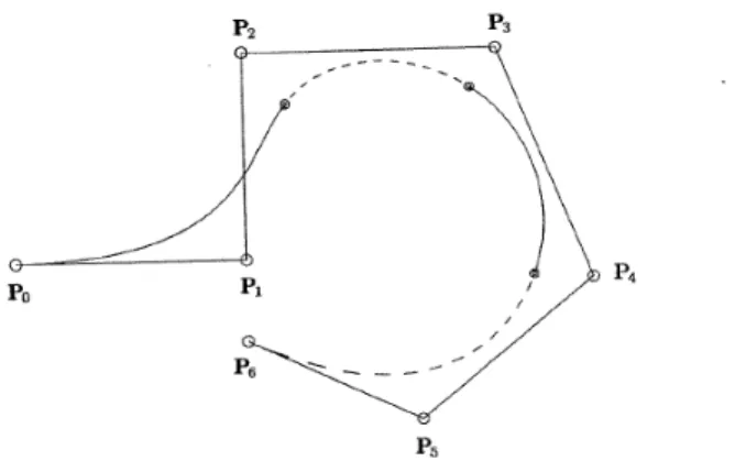
20 reduces the overall degree of the curve and improves the property of local modification. A B-spline curve of degree p with n control points consists of a series of n – p Bézier curve seg-ments. For instance, a cubic curve (degree p = 3) with n = 7 control points has 4 Bézier curve segments (Figure 2.5) and these segments all have C2 continuity at the join points. The con-tinuity degree is in terms of curve degree and repetition of knots in the knot vector. In gen-eral, it can be stated that the B-spline curve requires more computation, but is far more flex-ible and pleasant to work with, which is the reason why it has become part of almost every serious graphics development environment.
Figure 2.5: Cubic B-spline curve composed of four Bézier curve segments (Piegl & Tiller, The NURBS Book, 1997)
Before presenting the B-spline curve, first of all, it is necessary to define both the knot vector and the B-spline basis function. The joint points between these segments are called knots and they play a fundamental role in the understanding of this kind of curves. Consider-ing U = [u0, …, um] to be a non-decreasing sequence of real numbers, that is ui≤ ui+1, i = , …,
m; where ui are called knots, and U is referred to as the knot vector. The knot vector is used
to specify values in the evaluation interval where the curve changes the spline segment. By spacing the m intervals of the knot vector with equal distance, we obtain a uniform B-spline curve (for instance, U = {0,0,0,0,2,4,6,8,8,8,8}), while an uneven spacing (for instance, U = {0,0,0,0,1,5,6,8,8,8,8}) yields a non-uniform B-spline curve. Repeating a knot in the knots vec-tor (i.e. increasing the multiplicity) reduces the continuity of the curve at that knot. Thus, repeating the knots p times at the ends of the knots vector will make the B-spline to pass through the endpoints of the control polygon (for instance, U = {0,0,0,0,2,4,6,8,8,8,8}, the 0 is repeated three times same as the 8) .
When constructing a uniform B-spine curve, the basic functions translate each other, yielding a very simple basis function. The Cox de Boor algorithm can be found below, which can recursively computes any uniform (Figure 2.6) or non-uniform (Figure 2.7) B-spline basis function of n degree.
21
�, = { � ≤ < ℎ � }+ (2.5)
�, = +− − �, − + + ++ +− − + �+ , − (2.6)
Figure 2.6: Uniform cubic basis function defined on U = {0,0,0,0,2,4,6,8,8,8,8} (Piegl & Tiller, The NURBS Book, 1997)
Figure 2.7: Non-uniform cubic basis function defined on U = {0,0,0,0,1,5,6,8,8,8,8} (Piegl & Tiller, The NURBS Book, 1997)
As mentioned before, the B-spline curves share their properties with the Bézier curves, which are listed in the corresponding section. For more detailed information about the B-splines properties, the readers are invited to refer to The NURBS book (Piegl & Tiller, The NURBS Book, 1997). Regarding the Bézier curve, a B-spline curve requires some more addi-tional information (i.e. a knot vector and the degree of the curve) and its mathematical defi-nition is a bit more complex than Bézier curves. But, it has more advantages to compensate this shortcoming. Firstly, the degree of the B-spline is independent from the number of con-trol points which was the biggest shortcoming of the Bézier curves. The use of the knots vec-tor results in providing greater local control flexibility. In other words, by overcoming the limitations of the Bézier curve, we can create a B-spline curve of lower degree using large number of control points, thus supporting local modification. However, considering the fact that B-spline curves are still polynomial, they cannot be used to represent analytical curves (e.g. circles and ellipses). Therefore, a generalization of B-spline is required and introduced in the following section.
22
2.2.1.3 NURBS curves
The mathematical definition of NURBS curves is relatively simple. A NURBS curve is a vector valued piecewise rational polynomial function of the form:
= ∑= �, �
∑= �, ≤ ≤
(2.7)
where Ni,p(u) - normalized B-spline basis function of degree p, the Pi - control points, the wi
are the weights, and ui are the knots of a knot vector. The knot vector, for non-uniform and
non-periodic B-spline, has the following form:
U = {a, …, a, up+1, …, um-p-1, , …, }
he e the k ot e to e d s ith a and b which are repeated with multiplicity of p + 1 and in most practical application a = 0 and b = 1. The degree, number of knots, and number of con-trol points are related by the formula m = n + p +1. The NURBS curves share all important properties of the B-splines and Béziers curves, but for more detailed information concerning the property of NURBS, the reader can refer to (Piegl, On NURBS: A survay, 1991)
2.2.2 Bézier, B-Spline and NURBS surfaces
2.2.2.1 Bézier surfaces
The Bézier curve C(u) is a vector-valued function of one parameter u . A Bézier surface is a vector-valued function of two parameters, u and v, and represents a mapping of a re-gion, in a (u,v) plane parametric space into Euclidean three-dimensional space. S(u,v) = (x(u,v), y(u,v), z(u,v)), u,v ∈ R. The tensor product scheme is probably the simplest method, and the one most widely used in geometric modeling application.
The tensor product method is basically a bidirectional curve scheme. It uses basis func-tion and geometric coefficients. The basic funcfunc-tions are bivariate funcfunc-tion of u and v, which are constructed as product of univariate basis functions. The Bézier surfaces (Figure 2.8) are obtained by taking a bidirectional net of control points and products of the univariate Bern-stein polynomials:
23
, = ∑= ∑= �, ≤ , ≤ (2.8)
Figure 2.8: A quadratic x cubic Bézier surface
The Bézier surfaces share all important properties and limitations with the Bézier curves.
2.2.2.2 B-spline surfaces
A B-spline surface is obtained by using a bidirectional set of control points, two knot vectors (U and V), and the product of the univariate B-spline function. The B-spline tensor product surface is defined with the same parameters as B-spline curve, but every parameter is doubled, for both the u and v direction Figure 2.9.
, = ∑= ∑ = �, �, �, ≤ , ≤ (2.9)
Figure 2.9: A quadratic x cubic B-spline surface with U = {0,0,0,1/2,1/2,1,1,1} and V = {0,0,0,0,1/2,1,1,1,1}
Properties and limitations of the B-spline surfaces are similar to properties of B-spline curves, for each (u and v) direction separately (for more details see (Piegl & Tiller, The
24 NURBS Book, 1997). B-splines are a particular case of NURBS where all weights are equal to 1. The B-splines are far more stable and faster in representation of intersection but they are not able to represent analytics exactly. So, this is the reason why the mathematical formula-tion and properties of the NURBS have been presented below.
2.2.2.3 NURBS surfaces
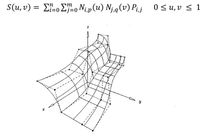
A NURBS surface is the rational generalization of the tensor product non-rational B-spline surface, but itself, the NURBS surface is, in general, not a tensor-product surface. A NURBS surface is a bivariate vector valued piecewise ration function of the form:
, = ∑= ∑= �, �, ,
∑= ∑= �, �, , �, ≤ , ≤ (2.10)
where p and q are the degree in the u and v direction respectively, Pi,j form a bidirectional
control net, wi,j are the weights, and the Ni,p(u) and Nj,q(v) are the non-rational B-spline basis
function defined over the knot vectors:
U = { , …, , up+1, …, ur-p-1, , …, }
V = { , …, , q+1, …, s-q-1, , …, }
where the end knots are repeated with multiplicities of p + 1 and q + 1, respectively, and the degrees, number of knots, and number of control points are related by the formulas r = n+p+1 and s = m+q+1. NURBS surface can be analyzed similarly using the bivariate rational basis function:
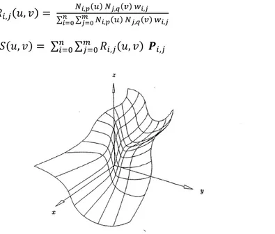
, , = ∑ �∑, � �, , �, ,
=
= , (2.11)
, = ∑= ∑ = , , �, (2.12)
Figure 2.10: Bicubic NURBS surface defined by the U = V = {0,0,0,0,1/2,1,1,1,1}, w1,1 = w1,2 = w2,1 = w2,2 = 10, wi,j = 1with I,j
25 In fact, the important properties of the Ri,j (u,v) are inherited from those of the
non-rational basis function Ni,p (u) and Nj,q (v) and the overall properties of the NURBS surface are
the same as the properties of NURBS curves.
NURBS (curves and surfaces) are standard methods for the representation and design of shapes in all CAD systems. Some reasons for the widespread acceptance and popularity of NURBS in the CAD systems and graphics community are as follows:
The mathematical formulation of the NURBS provides the possibility for representing both the analytic shapes (conics. quadrics. surfaces of revolution. etc.) and free-form shapes
NURBS provide the possibility to modify the shape by manipulating both the control points and the weights.
From the numerical computation point of view, their computation is reasonably fast and stable.
NURBS have understandable geometric interpretations, making them useful for those designers who have a very good knowledge in technical drawings.
Powerful capabilities have been defined for NURBS (such as knot inser-tion/refinement/removal, degree elevation, splitting, etc.), which can be used throughout to design, analyze, process, and interrogate objects.
NURBS, same as the other representation tools, are affine invariant under scaling, ro-tation, and translation.
The drawbacks of the NURBS are following:
The definition of a NURBS requires much more storage than it is needed to define tra-ditional curves and surfaces. For instance, the representation of a circle using NURBS requires 10 knots and 7 control points, whereas traditional representation requires the radius and the center.
The weights have strong influence to the parametrization; their improper application can affect the surface construction.
Surface to surface intersection perform better when using traditional forms than when usi g NU‘B“. Fo e a ple, it is e diffi ult to ha dle si ple tou hi g o o e lap-pi g of NU‘B“ su fa es.
The basic algorithms, such as inverse point mapping, are subject to numerical instabil-ity
It is important to be underlined that the problems listed before are not only typical for NURBS, but also other free-form schemes, such as those of Bezier, Coons, and Gordon, have the same problems.
26 2.3 Geometric modeling strategies
Geometric Modeling consists in defining realistic visualization of shapes in a computer graphic environment. In the background, the geometric modeling deals with mathematical methods for shape representation. The concept of geometric modeling has been initially introduced in the mid-1970s with the development of computer systems.
When designing complex product shapes that are not fully known in advance or do not exist yet, the usual geometric modeling procedure is interactive and involves the following steps (Patrikalakis, 2003):
Construction of the shape based on design requirements Evaluating the overall shape of the object
Improving the shape by modifying it until a satisfactory design is achieved
The aim of the Geometric modeling is to provide a complete, flexible and real repre-sentation of the object that is even not fully known, so that the shape of the object can be:
Realistic visualized (rendering)
Flexible for manipulation (modification)
Easily convert to a model that can be analyzed computationally Successfully manufactured and tested
2.3.1 Surface Modeling in product design
Before computer-aided surface modeling existed, automobile profiles had to be de-signed by making a clay model of car bodywork and, by trial and error methods, this model was shaped until aesthetically and functionally satisfactory. The geometry of the car body panels was then determined by physical measurement of the clay and stored in form of 2D technical drawings and documentations. The development of computer hardware and graphic introduces the possibility for developing computer-aided geometric modeling sys-tems. The development of the geometric modeling provides a fast and flexible platform for storing the geometry of a physical model that can be later used for visualization or manipu-lation. The basic geometri odeli g st ategies i luded i toda s o pute -aided design systems are: wireframe, surfaces and solid modeling. Wireframe modeling represents ob-jects by edge curves and vertices on the surface of the object. The wireframe model repre-sents the edges of the object in Euclidian 3D space, which is much better than projection of the edges onto a plane. The 3D wireframe model are nonetheless limited in that they cannot provide an unambiguous representation of the object and do not contain any information about the interior of the object (spatial addressability). Surface modeling defines objects
27 with greater mathematical integrity as it models the surfaces to give more definitive spatial boundaries to the design. Unlike the wireframe modeling, the surface modeling enables vis-ualizing more complex surfaces without producing a physical object (e.g. industry). The ben-efit of surface modeling using a computer is the possibility of having both the aesthetics and 3D geometry of the surfaces shape defined in one process. The surface models are types of 3D geometric models of a shape with no thickness. Clear differentiation between surface models and tick models has to be made because the latter have mass property, possibility of collision detection, and possibility for generation of finite element mesh. Solid modeling is the most advanced geometric modeling method for modeling in three dimensions. The com-plete geometric data representation of an object is ability to classify points in space relative to the object in terms if the point is inside, outside or on the object. The solid models are capable of handling spatial addressability as well as verifying that the model is well formed. The latter means that these solid models cannot verify whether two objects occupy the same space. Since the application domain of this work is the industrial design of products, the surface models are considered as a medium for transferring the aesthetic properties and the emotional affection to the customers. The surface models can be created using two dif-ferent groups of techniques divided in: free-form and subdivision surfaces, on the on hand, and B-Rep and declarative modeling, on the other hand. Therefore, these surface modeling techniques are listed in the following:
2.3.1.1 Free-form surface
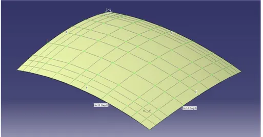
Free-form surfaces are widely used in all engineering design domains where the shape of the final product is more important from costumer point of view in terms of aesthetics. Therefore, the free-form surfaces modeling is also called the art of the engineering free-form surfaces. In general, there are two main methods for creating free-form surfaces: Lofting and Sweeping. Lofting represents an exact interpolation of a surface by using set of curves. Sweeping operation consists of creating a free-form surface by sweeping a profile curve along a trajectory curve in space. The most common types of spline that are using in design-ing free-form surface are the NURBS (Section 2.2.2). This is very important in cases where there is intersection of splines and analytic surfaces. The free-form surfaces are defined by control polygon and their modification depends more on the way how the free-form surfac-es is created. In case the surface is created using either loft or sweep, the modification of the surfaces is possible by modifying the profile curves (loft and sweep), or the trajectory curves (sweep). An alternative way of modifying of all free-form surfaces, regardless the way of creation, is possible by moving the control points (Figure 2.11). Such modification of free-form surfaces is very tedious, less intuitive and limits the creativity of the designers. The modification of free-form shapes, performed by manipulation low-level geometric entities (points and curves), does not provide certainty that the final shape will satisfy the aesthetic
28 requirements. Additionally, this character of the modification of free-form shapes discour-ages the non-designers to use them in designing their own products.
Figure 2.11: Free-form surface
2.3.1.2 Subdivision surfaces
Subdivision surfaces have become popular in animation and are gaining interest also in a computer aided design application. Usually, the modeling of complex and smooth surfaces such as those appeared in human character animation is by using trimmed patches of NURBS surfaces. Trimmed NURBS are wide spread in surface modeling because they are available in almost all existing commercial system but, according to DeRose et al. (DeRose, Kass, & Truong, 1998), they do have at least two major drawbacks: 1. trimming is a very time-consuming activity which tends to numerical error and 2. it is very difficult to preserve the smoothness at the joined edge of the surface patches during the animation of the model. Subdivision surfaces are capable to solve all problems related to the appearance of smooth surfaces including the two major difficulties of the trimmed NURBS surfaces. In other words, subdivision surfaces do not trim surfaces, and the smoothness of the model is automatically obtained even during the animation of the model (Figure 2.12).
On the other hand, the use of subdivision surfaces introduces new challenges through-out the production process, from modeling and animation to rendering. Regarding the mod-eling using subdivision surfaces discharges the designer from considering the topological restrictions that are mandatory for NURBS modelers, but at the same time they limit the use of manipulation (designing and modification) tools that have been developed before in order to add or modify features such as variable radius (e.g. hole or fillets) to NURBS models.
29
Figure 2.12: Catmull-Clark subdivision scheme (DeRose, Kass, & Truong, 1998)
Another application of subdivision is in multi-resolution of shapes (surfaces) where the representation of the shape is based on the continuous regular mesh and it is required by the need of representing of the shape in different level of details. In other words, a typical application of multi-resolution property is the real time rendering of large scenes, where an object near the viewer is represented in detail to increase the visual quality rendering, while an object farther away is represented at a coarser resolution to save rendering time. In addi-tion to this, multi-resoluaddi-tion property is also convenient in case where a modificaaddi-tion of the shape is required. For instance, the user can use the coarse resolution of the shape so as to be able to make a large scale modification or finer resolution in order to work on modifica-tion of details (Catalano, Ivrissimthis, & Nasri, 2007).
2.3.1.3 Boundary Representation (B-Rep)
Various representation modeling paradigms have been developed to create solid mod-els of real objects. Due to the importance of solid modeling, different solid modeling ap-proaches have been developed, divided in several groups: Constructive Solid Geometry (CSG), Boundary Representation (B-rep), cell decomposition, free-form parametric solids, swept volumes, and partial differential equations (You, Chang, Yang, & Zhang, 2011), (Hsu, 2010). There are two well-established and most popular modeling techniques for
represen-30 tation of solids in CAD systems (Hoffmann, Geometric and Solid Modeling: An Introduction, 1989), (Ault, 1999), (Hoffmann & Vanecek, Fundamental Techniques for Geometric and Solid Modeling, 1991): Constructive Solid Geometry (CSG) and Boundary Representation (B-Rep). Since the B-Rep can represent closed objects with free-form surfaces, this representation model will be presented in the following.
Boundary representation (B-Rep) is one of the most popular and widely used represen-tation schemas that can store all necessary information related to the object boundaries (vertices, edges, and faces). A B-Rep of a solid defines the solid as a set of oriented and con-nected faces forming a closed surface. The orientation of the bounding faces needs to easily decide easily between solid material and empty space (Figure 2.13). Thus, a boundary repre-sentation allows determining whether a given point is inside, outside, or on the boundary of a volume. The boundary of an object consists of vertices, edges, and faces. For each of these entities (vertex, edge, and face), the geometric part of the representation fixes the shape and/or location in space, and the topological part record the adjacencies. The combination of topological and geometrical information is a Boundary Representation (B-Rep) of a solid (Hoffmann & Vanecek, 1991).
The B-rep is widely adopted in computer graphics because it represents explicitly the information of the object enclosing surfaces (geometry and topology). The most important characteristic of the B-Rep modeling is that it is very convenient to construct solid model of irregular and complex shapes that are difficult to build using primitives (CSG). The B-rep modeling enables the representation of free-form shape that is extensively used in both aes-thetic and engineering design. This type of representation has been used for modeling ob-jects that will be further used in the investigation of the possibility for mapping aesthetics to surface shapes.
31 2.3.2 Procedural design process
The development of the Geometric modeling in computer graphics followed the re-quirements for designing significantly complex geometric models, which are also enriched with semantics. Earlier geometric models, such as polygonal model, NURBS, points, and so on, do not contain enough information, so that the models can be enriched with meanings. Higher-level modeling techniques have to provide an abstraction of the model, distinguish-ing classes of the objects, and to allow high-level manipulation of models (Ebert, Musgrave, Darwyn, Perlin, & Worley, 2003). Many of these advanced geometric modeling techniques are inherently procedural. Two major approaches exist to geometric modeling mechanisms, namely rule-based and imperative modelers (Bardis, Makris, Golfinopoulos, Miaoulis, & Plemenos, 2011). In rule-based modeler, the user designs the geometric model with the aid of a set of rules (Muller, Wonka, Haegler, Ulmer, & Van Gool, 2006), whereas in imperative modelers, the user defines the construction of the models through procedures following parameter values (Meiden, Hilderick, & Bronsvoort, 2007). The latter approach of modeling is the case with the majority of commercial CAD modeler, utilizing a history-based model in order to describe complex elements. The first approach (rule-based) is considered as declar-ative modeling where the abstraction is composed using intuitive terms provided by design environment. The second approach is the procedural modeling which aims at automatic cre-ation of large scenes in computer graphics through algorithms or sets of rules (Ganster & Klein, 2007).
The most common application of the procedural approach is in the creation of complex shapes or animation of phenomena too difficult to specify them explicitly. One type of the procedural modeling approach is the definition of shape grammars. The Shape Grammars (SG) has been introduced for the first time more than three decades ago by Stiny and Gips. In the recent years, SGs have been widely utilized in the CAD systems for reproducing large number of aesthetically consistent and novel designs (Stiny & Gips, 1971). The procedural modeling approach based on shape grammars depends on the identification of high quality grammar rules of the shape with sufficient accuracy, but in the meanwhile preserving a high degree of generality, in order for the system to create large variety of forms with numerous variations. The application of the rules generates designs, and the rules themselves are de-scriptors of the generated designs. The generation of variety of design shapes using shape grammars rules is a part of a design strategy called generative design (GD). The Shape Grammars (SG) together with L-systems (LS), cellular automata (CA), generic algorithms (GA), and swarm intelligence (SI) represent the five most commonly used Generative Design techniques (Singh & Gu, 2012),which are used as basis for developing the most existing GD systems.
The procedural design process is a type of design where the shape of the desired ob-ject is obtained by guiding the designer to follow previously defined designing steps. Ebert et
32 al. claimed that procedural shape generation techniques provide great flexibility, data ab-straction, and relief from specification of detailed shapes (Ebert, Advanced Geometric Modelling, 1997). Procedural techniques provide the shape to be manipulated by using high-level manipulation parameters. For instance, the user modifies the shape of a glyph from a more directorial, indirect aspect, where he/she is free from the entire explicit specification of detailed shapes. (Ebert, et al., 2000).
The term procedural modeling has wider meaning (e.g. geometric, system or process modeling), depending on which application domain is used. In general, the procedural mod-eling is a semiautomatic output generation using a rules or procedure. The possibility to generate a wide range of detailed data with minimum human involvement, opened perspec-tive for applying the procedural modeling in the field of virtual environments, increasingly used in movies, games, and simulations (Smelik, Tutenel, Bidarra, & Benes, 2014).
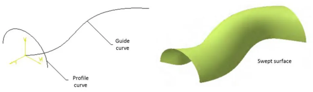
The advanced modeling techniques for designing surfaces are divided in three groups: 1: NURBS-based surfaces, 2. Linear surface manipulation (extrude and revolving), and 3. sweeping/lofting free-form surfaces. In many contemporary modeling systems, sweeping proves to be a practical, simple, and very efficient method for modeling various free-form surface shapes. The basic idea is to choose some geometrical object (generator, cross-section, profile), which is then swept along a curve (trajectory, guide) in space (Figure 2.14).
Figure 2.14: Sweeping profile curve along guide curve generation swept surface
The result of such evaluation, consisting of motion through space and intrinsic defor-mation, is a sweep object. The profile curve can be guided by one curve or two. The swept object type is determined by the choice of profile and guide curve and relationships among them Ma hl, Guid, O lo šek, & Ho at, 99 . Therefore, the procedure of definition of the swept surface consists of two vital steps:
1. Selection of profile curve
33 However, beside the easiness of creation of swept surfaces, their modifications still remain less intuitive and depend on modifying the shape of the profile and guide curves. The manipulation of the geometric quantities in order to modify the shape of the surface re-quires enhanced skills of the designers and foreknowledge of geometry. In addition, the modification of the shape is exceptionally difficult in case we want to modify the shape, but preserve its borders. This geometry-driven modification of shapes is not only far away less intuitive, but also does not ensure that the reached shape will satisfy the aesthetic con-straints and requirements. Therefore, it would be much better if the modification of the shape is aesthetic (emotion)-driven by the designers, whereas the manipulation of the ge-ometry is hidden in the modification tools.
2.3.3 Needs for intuitive modification of geometric models
In the field of industrial design, objects can be exposed to functional and aesthetic constraints such as shape aerodynamics, smoothness, and so on. In case where CAD soft-ware is considered, the deformation of the shape has to satisfy some geometric constraints, usually related to the functional requirements. Guillet and al. suggest that in order to signifi-cantly reduce the number of optimization parameters, the optimization of the shape of free-form surfaces mostly requests the use of a reduced set of global parameters for controlling of the surface deformation (Guillet & Léon, 1998). The deformation techniques of surfaces are devoted to the modification of the shape of objects.
The geometric representations (e.g. NURBS, B-Spline, Bézier, etc.) used in designing ac-tivities are characterized by a large number of control points. Further, the overall shape of an object must be decomposed into a set of NURBS surface patches to get a complete shape representation. Thus, without an appropriate three-dimensional modification tools for modi-fying the entire shape, the surface deformation leads the designer to tedious manipulation of a single patch (i.e. displacement of numerous control points). In order to obtain modifica-tion of the entire shape, the manipulamodifica-tion of a single patch has to be repeated for all patches of the shape. The basic aim of these deformation tools is to provide the user with easy and intuitive control of the surface shape. Since the geometry-driven deformation requires fore-knowledge of geometry and great skills in geometry manipulation, it is considered tedious and less intuitive. Therefore, it is very important, at the end of the deformation activity, that the final shape satisfies certain aesthetic properties as well – aesthetic-driven deformation.

![Figure 3.2: The link between the aesthetic character and the geometry is a two-level mapping [22]](https://thumb-eu.123doks.com/thumbv2/123doknet/2796926.66016/40.892.268.622.514.868/figure-link-aesthetic-character-geometry-level-mapping.webp)