Verification of a timed multitask system with U
PPAAL
∗Houda B
ELM
OKADEMLSV – CNRS UMR 8643 & ENS de Cachan,
61 av. du Pr´es. Wilson, F-94235 Cachan Cedex, France
[email protected]
B´eatrice B ´
ERARDLAMSADE – CNRS UMR 7024 & Universit´e Paris-Dauphine,
Place du Mar´echal de Lattre de Tassigny, F-75775 Paris Cedex 16
[email protected]
Vincent G
OURCUFF, Jean-Marc R
OUSSELand Olivier D
ES
METLURPA – EA 1385 – ENS de Cachan,
61 av. du Pr´es. Wilson, F-94235 Cachan Cedex, France
gourcuff, roussel, de [email protected]
Abstract
Since it is an important issue for users and system designers, verification of PLC programs has already been studied in various contexts, mostly for untimed programs. More recently, timed features were introduced and mod-eled with timed automata. In this case study, we consider a part of the so-called MSS (Mecatronic Standard Sys-tem) platform from Bosh Group, a framework where time aspects are combined with multitask programming. Our model for station 2 of the MSS platform is a network of timed automata, including automata for the operative part and for the control program, written in Ladder Diagram. This model is constrained with atomicity hypotheses concerning program execution and model checking of a
reaction time property is performed with the tool UPPAAL.
Keywords: Programmable Logic Controllers, Timed
Automata, Model Checking.
1
Introduction
Verification of safety properties for PLC (Pro-grammable Logic Controller) programs is important when these programs are to control critical applications for re-active systems. This explains the increasing interest in the past few years for the application of formal methods to the analysis of such programs. In this area, work was mostly devoted to the untimed framework [15], [4, 8], even when function blocks for timers were included [16].
∗This work was supported by the Pluri Formation Project VSMT of
ENS Cachan.
Introducing the study of quantitative properties related to time makes this verification step harder, because addi-tional components must be added in the model, for in-stance clocks, which increase the size of the model. How-ever, the model of timed automata, introduced in 1990 by Alur and Dill [2, 3], has proved very successful. Some decidability results were obtained for this model as well as for some extensions and they were implemented in effi-cient tools called timed model-checkers, like HYTECH[9],
KRONOS [6] or UPPAAL [11], which have been applied
to industrial case studies. Timed automata have recently been used for the modeling of timed features in PLC pro-gramming [13, 12, 7].
In this work, we are interested in the combination of time aspects with multitask PLC programming. Our case study concerns a part (called station 2) of the MSS (Meca-tronic Standard System) platform from Bosch Group, in which multitask programming can be used to reduce the reaction time of the control program to an external sig-nal. The program is written in Ladder Diagram, one of the languages most commonly used in this area, which is part of the IEC-61131-3 standard [10]. We give seman-tics for a subclass of Ladder Diagram programs including timer function blocks, in terms of timed automata, and we also provide a timed automata based model for the oper-ative part of the system. These timed automata are de-scribed in UPPAALsyntax. While a similar approach was introduced in [12], we propose here additional restrictions which allow us to reduce significantly the size of the com-plete model, obtained from its components by a synchro-nized product: these restrictions consist in atomicity hy-potheses, compacting sequences of actions from the con-trol program into a single one, and lead to reasonnable verification times for the response property to be checked.
We also give a simpler model for timers, using particular features of UPPAAL.
Section 2 of the paper explains the context of this study: the problem of reaction times in PLC programs, and includes a description of timed automata and a short presentation of UPPAAL. In Section 3, we give more de-tails on Bosch MSS platform and in Section 4, we give the semantics of the control program. Section 5 presents the timed automata which form the components of the net-work, while Section 6 gives the results of the verification step.
2
Programmable Logic Controllers and
Timed Automata
2.1 Programmable Logic Controllers with multi-task
programming
Programmable Logic Controllers (PLCs) execute pro-grams for the control of an operative part, to which they are connected via an input/output system. The control pro-grams can be written in several languages described in the IEC-61131-3 [10] standard. The execution of such a pro-gram consists in iterating a cycle with three main steps (figure 1): first, input variables are read and their values are stored in memory. Then a computation step is per-formed using these values, producing output values which are also stored. The last step is an activation using the out-put values. The cycle duration P is called the PLC scan.
P: PLC scan Program execution
Input scan
Output activation
Figure 1. The cyclic execution of a PLC pro-gram
The programming design may be either monotask or multitask. In the first case, a single program executes se-quentially, while in the second case, the main task can be interrupted by additional parts of code, either with a fixed period or triggered by some events. These two execution models result in different reaction times to changes of val-ues. In the monotask case, if the change of value occurs at the input scan, the corresponding output is emitted at the end of the PLC cycle. If the change occurs later, this out-put may be emitted at as far as the end of the next cycle. This results in a reaction time in the interval[P, 2P ] (fig-ure 2). This reaction time can be reduced with multi-task programming: consider an event-driven task interrupting the main task when some event occurs. In turn, the inter-rupting task reads its input and computes its new output
values. Depending on the configuration and type of the PLC, these values can be emitted either at the end of the event-driven task or at the end of the current main task. In this work, we investigate the second case where output values of the event-driven task are emitted by the main program, which yields a reaction time of at most P .
input i2
Input i1 output o1
output o2
Cycle 1 Cycle 2
Figure 2. Reaction time with mono-task pro-gramming
2.2 Timed automata
Timed automaton was introduced by Alur and Dill [2], [3]. It consists of finite automaton, which handles a finite set of variables called clocks. The clocks are used for the specification of quantitative time constraints which may be associated with transitions. These variables evolve syn-chronously with time (slope1).
For a set X of clocks,P(X) denotes the powerset of X and we defineC(X) as the set of conjunctions of atomic formulas of the form x ./ c for a clock x, a constant c and ./ in{<, ≤, =, ≥, >}.
A timed automaton is a tupleA = (Σ, X, Q, q0, I, E),
whereΣ is a finite set of actions, X is the finite set of clocks, Q is a finite set of locations, with q0∈ Q the initial
location, I is a mapping associating with each location q a clock constraint I(q) ∈ C(X), and E ⊆ Q × C(X) × Σ × P(X) × Q is the set of transitions.
The clock condition I(q) is called an invariant for location q, and contains usually only atomic formulas of the form x≤ c or x < c which must hold as long as time elapses in this location.
A transition of the automaton, written q−−−→ qg,a,r 0 ∈ E is
equipped with a label containing three parts (each one is optional): a guard g expressing a condition inC(X) on clock values, which must be satisfied for the transition to be fired, an action name inΣ, and a clock reset r ∈ P(X). The semantics of a timed automaton is given in terms of transition systems. A configuration of the system is a pair(q, v), where q is a location of the automaton and v is a valuation of the variables, i.e. a mapping associating a real value with each clock. The initial configuration is (q0, v0) where all clock values are equal to 0 in v0.
The system may change its configuration in two ways. • Either by a delay move of d time units, written
(q, v) −→ (q, v + d), possible if v + d satisfies thed invariant I(q) of location q.
• Or by an action move, written (q, v) −→ (qa 0, v0),
as-sociated with a discrete transition q−−−→ qg,a,r 0, if v
sat-isfies the constraint g. In this case, the reset operation yields v0(x) = 0 if x belongs to r and v0(x) = v(x)
otherwise, and v0must satisfy the invariant of q0.
2.3 The tool Uppaal
The tool UPPAAL(see [5] for the more recent devel-opments) offers a compact description language, a simu-lation module and a model-checker. A system is repre-sented by a collection for timed automata, which commu-nicate through binary synchronization: a channel c can be defined for two automata. Sending a message is denoted by the discrete action c! while receiving the message is de-noted by c?. An UPPAALautomaton also handles integer variables. A guard is a conjunction of atomic clock con-ditions and similar concon-ditions on integer variables. More-over, a clock reset may be augmented by an update of the integer variables.
A (global) configuration is of the form (`, v) where ` is a location vector (indicating the current state in each component of the timed automata network) and v is a valuation of both clocks and discrete variables. An execution in the network starts in initial locations of the different components with all the clocks and variables set to zero. The semantics of this model is expressed by moves between the configurations. Three types of moves can occur in the system: delay moves, internal moves and synchronized moves. Delay moves and internal moves have already been described above for a single automaton, so we simply describe now the global evolution.
Delaying. Given a current location vector, time elapses
for all automata synchronously, as long as no invariant is violated. All clock values increase by the amount of time elapsed. No change occur for the locations or the integer variables.
Performing an internal action. An internal action is an
action which corresponds to neither c! (sending a mes-sage), nor c? (receiving a message). If such an action is enabled (the variable values satisfy the guard condition), the component can perform this action alone, while the others do nothing. Only the location of this component is changed, as well as its variables, according to the transi-tion.
Synchronizing. If, in the network, some complementary
actions c! and c? are enabled in two components (in par-ticular, guards must be satisfied by the current valuation), then these components must synchronize. The location vector is changed for both components and the clock and variable values are changed according to the clock reset and updates of variables for the two transitions.
Finally, we introduce two additional features of UP
-PAALwhich will be very useful in our modeling.
• A committed location (decorated by the special label C) corresponds to a location in which no delay move is possible. Only a discrete transition can be used
to leave such a location. Note that this mechanism reduces the non-determinism in the parallel compo-sition of the different components.
• A broadcast channel is a channel where more than two automata may communicate: emission of a mes-sage c! can be synchronized with several receptions c? in other components. Note that this is a non-blocking synchronization, since the sender is never blocked, although the receiver must synchronize if it can. Guards on clocks are not allowed on the receiv-ing edge.
3
Description of the MSS (Mecatronic
Stan-dard System) platform
Figure 3. presentation of station 2 of the MSS platform
Presentation. Platform MSS (from Bosch Group)
pro-vides a function for sorting a stock of pinions of different materials and for adding or withdrawing a press-fit bush-ing to a given pinion [14].
Our study is centered on station 2 (figure 3) which is in-tended to identify the material of the pinion (steel, copper or black PVC) and the presence or absence of a press-fit bushing. The workpieces are transported by a linear conveyor to a scanning position, where the presence or absence of a press-fit bushing is detected. They are then tested by three sensors to determine their material. This is done using inductive, capacitive and optical sensors. The detected information is forwarded to the next stations. A rotary/lift gripper performs the transfer to a follow-on sta-tion if applicable.
Issue detected. A problem arises when the conveyor
arrives at the bearing test position (POS TESTsensor). At this time the conveyor moves at high speed (200 mm/s)
and the variation of the reaction time of the control sys-tem, above 10ms, is not negligible. Indeed the conveyor position should have a precision of 1mm for the tester (or jack) to be able to penetrate inside the pinion, in case the bearing is absent. So, we can deduce that the the variation of the reaction time of the control system must be less than 5ms. In the rest of the paper, we study the case of a multitask controller, with an event-driven task, launched on the rising edge of the test position (POS TEST) sensor, which stops the conveyor if it comes from the loading station.
Properties to check. The multitask control program of
this station must satisfy the following properties:
P1 To ensure safety, the conveyor must stop on its way
out but not when it comes back from unloading.
P2 The time performance is accurate: the conveyor stops
in less than 5ms at the press-fit bushing test point. In this work, we focus on the timed property P2, to show that the multitask solution reduces the reaction time.
4
Modeling principles
In this section, we briefly recall the timed automaton based semantics proposed by Mader and Wupper [12] for a control program. Then we explain the structure of our model for (station 2 of) the MSS platform, with a particu-lar attention to the question of timers.
4.1 Mader-Wupper model
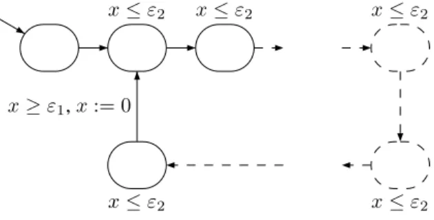
Various models have already been proposed for the analysis of PLC programs. Our approach is based on the model introduced by Mader and Wupper [12], which dis-regards the execution times of elementary instructions.
x≥ ε1, x:= 0
x≤ ε2 x≤ ε2 x≤ ε2
x≤ ε2
x≤ ε2
Figure 4. Mader-Wupper model
As depicted in figure 4, the model has a clock x to measure the cycle scan, which is thus reset after each cy-cle of the program. The invariant x ≤ ε2 is associated
with each location and represents an upper time bound for each whole scan. The guard x ≥ ε1appears on the last
edge of the cycle and represents a lower time bound for the input/output part of the cycle. An edge in the model describes a step of the control program.
Mader-Wupper also models each timer block as a timed automaton that runs in parallel with the control program. Synchronization is performed through operations on the timer variables and on the timer calls, which requires one extra clock and three synchronization channels for each timer.
4.2 An overview of the model
Our model is built in a compositional way from a col-lection of non deterministic processes with finite control structure and real-valued clocks, communicating through channels or shared variables. The two main parts are the environment and the control program, which communi-cate through shared variables and synchronization mes-sages. The modeling of the operative part (environment) is necessary for the verification of the safety and perfor-mance properties stated previously. The details are ex-plained in Section 5.
4.3 Modeling timers
Six independent timers (TON function block in IEC-61131-3 [10]) are used in station 2 control program. We now explain how our model of a TON function block dif-fers from that of Mader-Wupper [12] and how we used broadcast channels in UPPAALto avoid deadlocks. Each TON block is modeled by an automaton, described in fig-ure 5, with three states, one clock x-Ton and two discrete variables Ton-ine (input) and Ton-Qe (output). Initially
idle, the state becomes running when the timer has been
switched on and Timeout, when some fixed preset delay (constant Ton pte) has been reached. At each cycle of the main task, a synchronization message is sent. The au-tomaton is then forced to evolve by taking into account the new values of the variables computed by the previous cycle. A deadlock could occur if the automaton is in a state where it cannot receive the synchronization message of the program. So we chose a single broadcast channel for all TON blocks instead of three ordinary channels per TON in Mader-Wupper’s model.
idle running x_Ton <= Ton_pte Timeout Ton_ine == 1 TON? Ton_Qe := 0, x_Ton:=0 Ton_ine==0 TON? ( x_Ton == Ton_pte ) && Ton_ine ==1 Ton_Qe := 1 Ton_ine == 0 TON? Ton_Qe := 0
5
Modeling with U
PPAAL5.1 Modeling the environment
Interest. In order to validate not only the PLC program
but also its integration in the system it has to control, we also need to model the operative part. This implies a thor-ough knowledge of the system to control, particularly the behavior of each element and its reaction time. Modeling the environment makes it possible to speed-up the veri-fication time, in particular by reducing the combinatorial aspects related to non deterministic definition of all possi-ble input values, including sometimes non relevant ones. Indeed, when the input values of the PLC program are emitted by a model instead of a non deterministic process, the space of reachable states is reduced. However, these parts of the model are usually limited to the representation of nominal operation modes, which is the case here.
Modeling. Each physical device is represented by a timed
automaton. In such an automaton, a given location repre-sents a particular configuration of the device. In the mod-els proposed here, clocks are the only continuous com-ponents, while physical continuous moves are discretized (for instance for the conveyor).
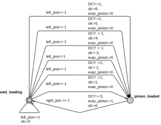
The external environment. In station 2, the leftmost
po-sition corresponds to the loading of pinions, while the rightmost position is used for unloading. However, the control of loading and unloading operations is not part of this station, which just waits for them to be done. Infor-mation about termination of one of these operations is ob-tained through changes of input values. Upon loading, the conveyor is provided an unspecified pinion. This is mod-elled by an automaton, presented in figure 6, which selects in a non deterministic way the nature of the pinion (vari-able ob) when the conveyor is at the rightmost position.
wait_loading pinion_loaded left_pos== 1 DCY :=1, ob:=1, evac_pinion:=0 DCY:= 0, evac_pinion:=1, ob:=0 right_pos == 1 left_pos== 1 DCY := 1, ob:=4, evac_pinion:=0 left_pos==1 DCY := 1, ob:= 3, evac_pinion:=0 left_pos== 1 DCY :=1, ob:= 2, evac_pinion:=0 left_pos== 1 DCY:=1, ob:=5, evac_pinion:=0 left_pos== 1 DCY:=1, ob:=6, evac_pinion:=0 left_pos==1 ob:=0
Figure 6. Model of the environment external to station 2
The jack. The jack detects the presence or absence of
a press-fit bushing in a workpiece. This test is made by a vertical movement of the jack until a limiting
posi-top go_down limiting_position
down_jack? up_jack? up_jack? jack_down:= 0 ob==1 || ob==5 || ob == 3, pos_test==1 down_jack? up_jack? down_jack? ob==0 ||ob==2 || ob == 4 || ob == 6|| ((ob==1 || ob==3 || ob==5) && pos_test ==0)
down_jack?
jack_down:=1
Figure 7. Timed automaton for the jack.
tion. The jack must go down until the limiting position is reached, in a given time, to conclude to the absence of the press-fit bushing. The model of this sensor (figure 7) de-pends on the characteristics of the workpieces which are represented by the values of the variable ob. The automa-ton starts from the state top. He moves to state go down when he receives a message down-jack? from the PLC program. From this point on, there are two cases: if there is a press-fit bushing in the workpiece (represented in the model by the guard ob == 1||ob == 3||ob == 5) then the automaton waits in the state go down, else the automa-ton moves to state limiting position.
The sensors. The optical, capacitive and inductive
sen-sors are modeled by automata synchronized with the au-tomaton of the conveyor. The conveyor sends the activa-tion messages (for example optics? in figure 8) when it is under the corresponding sensor. According to the nature of the material, the sensor modifies the value of the corre-sponding variable (optical) which is then used by the PLC program. idle x_co <= 400 ob==1||ob==2||ob==3||ob==4 optical:=1, x_co:=0 optics? x_co == 400 optical:= 0 ob==0 || ob==5 || ob==6 optics?
x_co:=0
Figure 8. Timed automaton for the optical sensor.
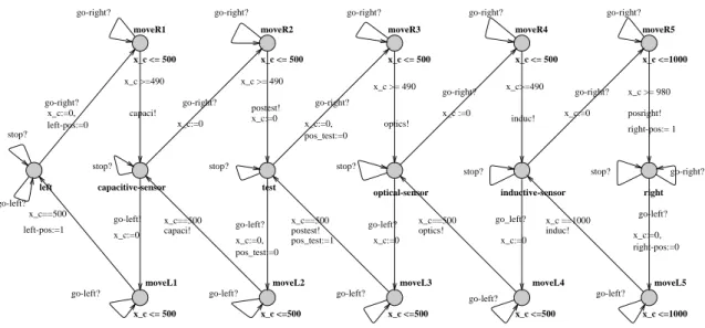
The linear conveyor. The conveyor is the main element
of the operative part: several triggerings of sensor depend on its position. The conveyor is also the most delicate to model because of its continuous behavior along the belt, while our model can only provide a discrete abstraction of this behavior, leaving out the details which do not in-fluence the properties to be checked. In order to obtain reasonable performances in terms of memory and auto-matic verification time, we model only the almost sta-ble positions, i.e. the positions where the conveyor can stop, or trigger a sensor. These positions correspond to the six states: inductivesensor, capacitivesensor,
optical-left moveR1 x_c <= 500 moveR2 x_c <= 500 moveR3 x_c <= 500 moveR4 x_c <= 500 moveR5 x_c <=1000 moveL1 x_c <= 500 moveL2 x_c <=500 moveL3 x_c <=500 moveL4 x_c <=500 moveL5 x_c <=1000 capacitive-sensor test
optical-sensor inductive-sensor right
go-right? x_c:=0, left-pos:=0 x_c >=490 capaci! go-right? x_c:=0 x_c >= 490 postest! x_c:=0 go-right? x_c:=0, pos_test:=0 x_c >= 490 optics! go-right? x_c :=0 induc! x_c>=490 go-right? x_c:=0 x_c >= 980 posright! right-pos:= 1 go-left? x_c:=0, right-pos:=0 x_c ==1000 induc! go_left? x_c:=0 x_c==500 optics! go-left? x_c:=0 x_c==500 postest! pos_test:=1 go-left? x_c:=0, pos_test:=0 x_c==500 capaci! go-left! x_c:=0 x_c==500 left-pos:=1 stop? go-left?
stop? stop? stop?
stop? stop? go-right? go-right? go-right? go-right? go-right? go-right?
go-left? go-left? go-left?
go-left? go-left?
Figure 9. Timed automaton for the conveyor.
sensor, test, lef t, right. Between two given positions, we model the behavior of the conveyor by only one state with an invariant which represents the time needed by the conveyor to cross the distance between these two posi-tions. For example, the conveyor goes from the left po-sition to the capacitive-sensor popo-sition in 490 to 500ms. There is another abstraction imposed by the fact that no stopwatch exists in UPPAAL: between two almost stable positions, the conveyor cannot change direction. The con-veyor sends messages of synchronization to the various sensors (like optics!) and the event-driven task (postest!) at the time of its arrival to the test position. It also modi-fies the input variables of the control program. The corre-sponding automaton is represented in figure 9.
5.2 The control program
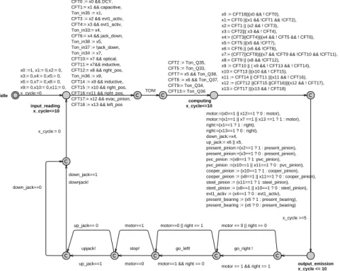
The main program. The functional specification of the
global system is designed in GRAFCET (or SFC) lan-guage, and further implemented in Ladder language. As explained above, the execution of a PLC program is a cy-cle with three phases: input reading, computation of new values and output writing. This periodic operation is mod-eled in UPPAALby an automaton structured as a loop, and including a clock to measure the cycle time (equal to10 u.t. here). The complete cycle of the automaton for the ladder program thus consists of a loop with four steps:
1. input reading and computation of new values for the evolution conditions of the GRAFCET,
2. computation of other new values for GRAFCET vari-ables: step activation and output computation, 3. output writing, performed by a sequence of messages
for synchronization with the operative part, 4. reset of the clock modeling the cycle time.
The atomicity hypothesis is the following: time can elapse only in the three states between these steps, to represent the duration of their execution.
The event-driven program. Since it is run upon
acti-vation of the bushing-test position, the event-driven task is strongly dependent on the environment. This aspect is modeled by the emission of a message from the environ-ment, received by the automaton of the event-driven task (figure 11). idle postest ? i2==1|| i3 == 1 motor:=0, evt1_activ:= 1 i2==0 && i3 ==0 motor==0 stop! motor==1 X3 MOTOR EVT1_ACTIV X2
Figure 11. UPPAAL model and Ladder Dia-gram for the event-driven task
When the message postest! is emitted, the automaton executes the algebraic equations which represent the Lad-der program and sends the output message stop! if the condition holds. Note that the execution time of the even-driven task is null due to the committed location used to model the priority of the event-driven task. Various pro-gramming designs are considered in order to determine the conditions under which the requirements are satisfied:
idle input_reading x_cycle<=10 output_emission x_cycle <= 10 computing x_cycle<=10 x0 :=1, x1:= 0,x2:= 0, x3:= 0,x4:= 0,x5:= 0, x6:= 0,x7:= 0,x8:= 0, x9:= 0,x10:= 0,x11:= 0, x_cycle:=0
motor == 1 && right == 1 go_right !
motor==1 && right == 0 go_left! motor==0 stop! up_jack==1 upjack! down_jack==1 downjack! motor == 0 || right == 0 motor==0 || right == 1 motor==1 up_jack== 0 down_jack==0 x_cycle:= 0 x_cycle >=5 x0 := CFT18||(x0 && ! CFT0), x1:= CFT0 ||(x1 && !CFT1 && !CFT2), x2:= CFT1 || (x2 && ! CFT3), x3:= CFT2||( x3 && ! CFT4), x4:= (CFT3||CFT4)||(x4 && ! CFT5 && ! CFT6), x5:= CFT5 ||(x5 && !CFT7), x6:= CFT6 || (x6 && !CFT8),
x7:= (CFT7||CFT8)||(x7 && !CFT9 && !CFT10 && !CFT11), x8:= CFT9 || (x8 && !CFT12), x9 := CFT10 || ( x9 && ! CFT13 && ! CFT14), x10:= CFT13 ||(x10 && ! CFT15), x11 := CFT14 || CFT11 ||(x11 && ! CFT16), x12 := (CFT12 ||CFT15 ||CFT16)||(x12 && ! CFT17), x13:= CFT17 ||(x13 && ! CFT18) CFT0 := x0 && DCY, CFT1:= x1 && capacitive, Ton_in35 := x1, CFT3 := x2 && evt1_activ, CFT4:= x3 && evt1_activ, Ton_in33:= x4, CFT6:= x4 && jack_down, Ton_in38 := x5, Ton_in37 := !jack_down, Ton_in34 := x7, CFT10:= x7 && optical, CFT11:= x7&& inductive, CFT12:= x8 && right_pos, Ton_in36 := x9, CFT14 := x9 && inductive, CFT15 := x10 && right_pos, CFT16:=x11 && right_pos, CFT17:= x12 && evac_pinion, CFT18 := x13 && left_pos TON! CFT2 := Ton_Q35, CFT5 := Ton_Q33, CFT7:= x5 && Ton_Q38, CFT8 := x6 && Ton_Q37, CFT9:= Ton_Q34, CFT13:= Ton_Q36 motor:=(x0==1 || x12==1 ? 0 : motor), motor:=(x1==1 || x7 ==1 || x13 ==1 ? 1 : motor), right:=(x1==1 ? 1 : right), right:=(x13==1 ? 0 : right), down_jack:=x4, up_jack:= x6 || x5, present_pinion:=(x2==1 ? 1 : present_pinion), present_pinion:=(x3==1 ? 0 : present_pinion), pvc_pinion :=(x8==1 ? 1 :pvc_pinion), pvc_pinion :=(x10==1 || x11==1 ? 0 : pvc_pinion), cooper_pinion := (x10==1 ? 1 : cooper_pinion), cooper_pinion := (x8==1 || x11==1 ? 0 : cooper_pinion), steel_pinion := (x11==1 ? 1 :steel_pinion), steel_pinion := (x8==1 || x10==1 ? 0 : steel_pinion), evt1_activ := (x4==1 ? 0 : evt1_activ), present_bearing := (x5 ? 1 : present_bearing), present_bearing := (x6 ? 0 : present_bearing)
Figure 10. UPPAAL model of main program
• the event-driven task only modifies the internal mem-ory of the output,
• the event-driven task is not activated.
6
Verification with U
PPAALThe observer automaton. In order to verify the timed
property P2, we need an additional automaton (see be-low), which plays the role of an external observer with respect to the model previously described.
idle obs stop postest ? X:=0 i2==1 || i3==1 stop? X:=0
This automaton contains a state stop, reached when the conveyor stops in testing position. It also contains a clock X to measure the reaction time. The observer automa-ton starts from state idle with X set to0. When the mes-sage postest? is received from the conveyor, the automa-ton moves to state obs and resets the clock X. From this point on, the clock value again increases with time. When the message stop? is received from the main program, the automaton switches to state stop. Thus, the value of X in this last state corresponds to the time elapsed between the triggering of the event-driven task and the physical stop of the conveyor. To check the timed property P2, we express
its negation (C1 in the table below): the observer automa-ton will eventually reach the state stop with the value of the clock X greater than 5 time units. This property is written as
E<> (obs.stop and X >5)
in UPPAAL syntax, which is a fragment of the logic
TCTL [1]. In this formula, the combinationE<> means “for some path in the future” and obs.stop denotes loca-tion stop of the observer automaton.
Experiments. First note that the global model has about
30.106
configurations, which are explored in an on the fly computation of the set of reachable states. The table below gives the time and memory used for verification (on a linux machine with a pentium4 at 2.4 GHz with 3 Go RAM). The results provide a comparison of the reaction times between monotask and multitask programming. Indeed, on one hand, properties C5, C6 and C7 show that the conveyor stops between 10 and 20 time units after it reaches the test position. This is far from being a surprise because these values correspond respectively to one and two PLC cycle times. On the other hand, property C3 shows that the conveyor stops in less than one PLC cycle time. So, multitask programming reduces the reaction time. However, property C1 proves that it is not sufficient to satisfy the requirement P2.
Note that, after 29 hours of computation, we stopped the verification process in the case of Mader-Wupper model.
property result time memory with the event driven task
C1:E<> obs.stop and X > 5 yes 15 s 30 Mo C2:E<> obs.stop and X ≤ 5 yes 15 s 30 Mo C3:E<> obs.stop and X > 10 no 22 s 61 Mo without the event driven task
C5:E<> obs.stop and X ≥ 10 yes 16 s 30 Mo C6:E<> obs.stop and X > 20 no 22 s 70 Mo C7:E<> obs.stop and X < 10 no 22 s 69 Mo with Mader-Wupper model
C8:E<> obs.stop and X > 5 - -
-These performances are due to two main reasons: the atomicity hypothesis for executions between some states of the main program and the enhanced model of the TON block.
• The atomicity hypothesis: we assume that each one of the four steps of the main program (section 5.2) executes instantaneously. Recall that time can elapse only in three states.
• The enhanced model of the TON block: we use one broadcast channel to synchronize all the TON blocks and the main program instead of three ordinary chan-nels for each TON block as in Mader-Wupper model.
7
Conclusion
In this work, we give formal semantics to (partial) Lad-der diagrams and TON blocks, with timed automata. We also describe the operative part of station 2 of MSS plat-form with timed automata. On this network of timed au-tomata represented in UPPAALsyntax, we formally prove by model-checking that multitask programming reduces the reaction time of the conveyor, upon emission of an output order to stop. While this does not really come as a surprise, we obtain reasonable verification times (less than 30s) on a global model with about30.106
states, by adding an atomicity hypothesis to Mader-Wupper model and modifying the automata for timer blocks. In compar-ison, model-checking the same formula with the original model had to be stopped after several hours.
References
[1] R. Alur, C. Courcoubetis, and D. L. Dill. Model-checking in dense real-time. Information and
Computa-tion, 104(1):2–34, 1993.
[2] R. Alur and D. L. Dill. Automata for modeling real-time systems. In Proc. 17th Int. Coll. Automata, Languages,
and Programming (ICALP’90), Warwick University, Eng-land, July 1990, volume 443 of Lecture Notes in Computer Science, pages 322–335. Springer, 1990.
[3] R. Alur and D. L. Dill. A Theory of Timed Automata.
The-oretical Computer Science (TCS), 126(2):183–235, 1994.
[4] G. Canet, S. Couffin, J.-J. Lesage, A. Petit, and Ph. Schnoe-belen. Towards the automatic verification of PLC programs written in Instruction List. In Proc. IEEE Int. Conf.
Sys-tems, Man and Cybernetics (SMC’2000), Nashville, TN, USA, Oct. 2000, pages 2449–2454, 2000.
[5] A. David, G. Behrmann, K. G. Larsen, and W. Yi. A Tool Architecture for the Next Generation ofUPPAAL. Techni-cal Report 2003-011, Department of Information Technol-ogy, Uppsala University, Feb. 2003. 20 pages.
[6] C. Daws, A. Olivero, S. Tripakis, and S. Yovine. The tool KRONOS. In Proc. Workshop Hybrid Systems III:
Verifi-cation and Control, New Brunswick, NJ, USA, Oct. 1995,
volume 1066 of Lecture Notes in Computer Science, pages 208–219. Springer, 1996.
[7] H. Dierks. PLC-Automata: A New Class of Imple-mentable Real-Time Automata. Theoretical Comput. Sci., 253(1):61–93, 2000.
[8] G. Frey and L. Litz. Formal methods in PLC-programming. In Proc. IEEE Int. Conf. Systems, Man and
Cybernetics (SMC’2000), Nashville, TN, USA, Oct. 2000,
pages 2431–2436, 2000.
[9] T. A. Henzinger, P.-H. Ho, and H. Wong-Toi. A user guide to HyTech. In Proc. 1st Int. Workshop Tools and
Algorithms for the Construction and Analysis of Systems (TACAS’95), Aarhus, DK, May 1995, volume 1019 of Lec-ture Notes in Computer Science, pages 41–71. Springer,
1995.
[10] IEC (International Electrotechnical Commission). IEC Standard 61131-3 : Programmable controllers - Part 3,
1993.
[11] K. G. Larsen, P. Pettersson, and W. Yi. UPPAAL in a nut-shell. Journal of Software Tools for Technology Transfer, 1(1–2):134–152, 1997.
[12] A. Mader and H. Wupper. Timed automaton models for simple programmable logic controllers. In Proc. 11th
Eu-romicro Conference on Real-Time Systems (ECRTS’99), York, UK, June 1999, pages 114–122. IEEE Comp. Soc.
Press, 1999.
[13] E. Olderog. Correct real-time software for programmable logic controllers. In Correct System Design. Recent
In-sights and Advances, volume 1710 of Lecture Notes in Computer Science, pages 342–362. Springer, 1999.
[14] Rexroth Bosch Group. Mechatronik standard system. http://www.boschrexroth.com/country_ units/europe/germany/sub_websites/ brs_germany/de/didactic/lehrsysteme/ mechatronik/mechatronik_standard_ system_mss/index.jsp.
[15] O. Rossi, O. de Smet, S. Lamprire-Couffin, J.-J. Lesage, H. Papini, and H. Guennec. Formal verification: a tool to improve the safety of control systems. In 4th Symposium
on Fault Detection, Supervision and Safety for Technical Processes (IFAC Safeprocess 2000), Budapest, Hungary,
pages 885–890, 2000.
[16] O. Rossi and Ph. Schnoebelen. Formal modeling of timed function blocks for the automatic verification of Ladder Diagram programs. In Proc. 4th Int. Conf.
Au-tomation of Mixed Processes: Hybrid Dynamic Systems (ADPM’2000), Dortmund, Germany, Sept. 2000, pages