HAL Id: hal-01240221
https://hal.archives-ouvertes.fr/hal-01240221
Submitted on 8 Dec 2015
HAL is a multi-disciplinary open access
archive for the deposit and dissemination of
sci-entific research documents, whether they are
pub-lished or not. The documents may come from
teaching and research institutions in France or
abroad, or from public or private research centers.
L’archive ouverte pluridisciplinaire HAL, est
destinée au dépôt et à la diffusion de documents
scientifiques de niveau recherche, publiés ou non,
émanant des établissements d’enseignement et de
recherche français ou étrangers, des laboratoires
publics ou privés.
Integrated Sensor: A Backdoor for Hardware Trojan
Insertions?
Xuan Thuy Ngo, Zakaria Najm, Shivam Bhasin, Debapriya Basu, Jean-Luc
Danger, Sylvain Guilley
To cite this version:
Xuan Thuy Ngo, Zakaria Najm, Shivam Bhasin, Debapriya Basu, Jean-Luc Danger, et al.. Integrated
Sensor: A Backdoor for Hardware Trojan Insertions?. Euromicro Conference on Digital System Design
(DSD) 2015, Aug 2015, Funchal, Portugal. �10.1109/DSD.2015.119�. �hal-01240221�
Integrated Sensor: A Backdoor for Hardware Trojan
Insertions?
Xuan Thuy Ngo
∗, Zakaria Najm
∗, Shivam Bhasin
‡, Debapriya Basu Roy
§, Jean-Luc Danger
∗†, Sylvain Guilley
∗†∗ Institut MINES-TELECOM, TELECOM ParisTech, CNRS LTCI (UMR 5141). † Secure-IC S.A.S., 80 avenue des Buttes de Co¨esmes, 35 700 Rennes, FRANCE.
‡ Temasek Laboratories, NTU, Singapore. § Indian Institute of Technology, Kharagpur.
Abstract—Embedded system face a serious threat from physi-cal attacks when applied in critiphysi-cal applications. Therefore, mod-ern systems have several integrated sensors to detect potential threats. In this paper, we put forward a new issue where these sensors can open other security loopholes. We demonstrate that sensors, which are deployed to prevent faults, can be exploited to insert effective and almost zero-overhead hardware Trojans. Two case studies are presented on Xilinx Virtex-5 FPGA. The first case study exploits the in-build temperature sensor of Virtex-5 system monitors while the other exploits a user deployed sensor. Both the sensor can be used to trigger a powerful Trojan with minimal and at times zero overhead.
Index Terms—SoC, Hardware Trojan, Backdoor, On-chip Sen-sor, System Monitor, Cryptographic circuit, Advanced Encryp-tion Standard, Elliptic curve digital signature algorithm, Piret attack, Side Channel attack, ASK modulation, FSK modulation, CFGLUT, Security test plans.
I. INTRODUCTION
As more and more semiconductor companies are welcoming the outsourcing trend to be competitive, they are opening new security loopholes. One such threat which came to light few years ago is the Hardware Trojan (HT) insertion. A HT is a malicious module inserted in an Integrated Circuit (IC) during design or fabrication stage. Once inserted, HT can perform various dangerous tasks such as Denial of Service (DoS), leakage of sensible data via circuit outputs, etc [7]. Any HT has two basic components:
• Trigger: which reads the target circuit state (to trigger its malicious function).
• Payload: which writes on the target circuit state (to executes its malicious function).
Once inserted, we cannot remove a HT. Therefore HT has become a hot topic in the hardware security field.
Many researchers have looked into the topic of HT insertion and demonstrated some really small and intelligent Trojans. In [8], authors implement a malicious HT on a Leon3 proces-sor that maliciously grants root-level privileges to an attacker, creating a permanent backdoor into a system and also steals passwords from other users of the system. Authors in [4] show Xuan Thuy Ngo is the corresponding author. This project has been funded by the French Government, under grant FUI #14 HOMERE 959 (Hardware trOjans : Menaces et robustEsse des ciRcuits intEgr´es).
an example of HT inserted in AES coprocessor at the layout level. Another work [7] show some HT implementations for malicious task like leaking the key or permanently destroying the chip. A rich collection of HT implementation can be found at www.trust-hub.org for different target. In most of these HT examples, we noticed that an HT becomes detectable mainly due to the trigger part. This is because firstly HT trigger needs access to IC inputs or internal nets to trigger the malicious function. Therefore HT risk activation and detection during the test phase with some advanced testing technique developed for HT detection purpose as [5], reconfigurable logic [1], logic testing [2]. Secondly, HT trigger is much bigger than the HT payload part which makes it susceptible to detection techniques. Generally, attacker must find a compromise be-tween HT size and HT function.
Another trend in IC design for critical application is the use of integrated sensors. Several applications which need security and reliability deploy physical sensors to detect any irregular working conditions. These sensors monitor parameters like voltage, temperature, pressure, glitches etc. Although the sen-sors are deployed to protect against certain attacks like faults. However, sometimes these sensors can open backdoor for new attacks.
In this paper, we make an attempt to exploit sensors existing in a device to design extremely small and powerful HT. We basically use sub-threshold condition of the deployed sensors to trigger a hardware trojan without any internal connection to the IC. We precisely present two case studies. The first case study, exploits the in-built temperature sensor inside the Xilinx Virtex-5 system monitor module. Using an output of this module, we demonstrate a zero-overhead HT to inject faults in a AES crypto-processor running on the chip. In the second case-study, we exploit a user designed sensor. It is not uncommon to find user designed sensors in ICs. We exploit a ring-oscillator based sensor probe sensor proposed at CHES 2014 [6] by Homma et al. The sensor is exploited to insert a hardware trojan which leaks secret parameters of a ECC exponentiation computation.
The main objective of this paper is to raise the issue of security policy in IC design. We aim to make the designers aware that simply adding a countermeasure is not sufficient.
It is more important to test and verify by deploying proper policies, that the introduced countermeasure does not brings more pitfalls than strength.
We show 2 case study on HT insertion using system monitor and probe sensor to demonstrate this threat. The rest of this paper is organized as follow: Sec. II gives some background on hardware security. Sec. III presents integrated sensors that we use in our case studies. Sec. IV present 2 case study for HT insertion by exploiting these integrated sensors. In Sec. V, we discuss our results followed by conclusions in Sec. VI.
II. GENERALBACKGROUND
In this section, we give a small background on hardware se-curity, fault attacks and elliptic curve cryptography to facilitate understanding of rest of the papers.
A. Hardware Security
Embedded applications with strong security requirements use sophisticated cryptographic algorithms and protocols. These algorithms and protocols are usually considered resis-tant against cryptanalysis. In a system, encryption algorithms can be implemented either in software or in hardware. Unfortu-nately, any computation is eventually performed by a piece of hardware (microprocessor or hardware dedicated accelerator). Every hardware device leaks symptoms of its activity (power consumption, electromagnetic emanations, computation time, sounds, temperature variations, etc.). An attacker can use such “side-channels” to retrieve embedded secrets.
An attacker can also inject faults by modifying the power supply, the clock frequency or even by modifying the structure of the device. Such attacks are popularly known as Fault Injection Attack (FIA). The main idea of FIA is to corrupt the program during its execution to create one or multiple faults. An attacker can exploit these faults to extract sensitive informations. For instance, in AES which is the current NIST standard for symmetric cryptography, it has been demonstrated that 2 well located faults are enough to extract the secret key [9]. For the attack to be successful, fault must be injected in any byte of AES internal state, during the computation of penultimate or 8th round of the cipher. The fault must inject
the same byte for two different execution of the ciphers with different inputs.
Depending on the attacker strength and underlying target, the fault injection mechanism can be chosen. Fault injection involves disturbing physical parameters of target circuit. The fault injection setup can inject either global or local faults. Global fault injections are performed by varying environment parameters such as Temperature, Voltage or by varying IC frequency. These technique are easy to mount but lack pre-cision. The alternative is local fault injections that can be done using Laser or Electromagnetic (EM) injection. Such setups are expensive but can provide extreme precision. Now it depends on the attacker to use expensive equipment to inject 2 faults with expensive equipment or inject several faults with cheap setup until 2 good faults occur.
B. Elliptic Curve Cryptography
Generally all cryptographic encryption algorithms can be broadly classified into two classes: private key crypto-system and public key crypto-system. Elliptic Curve Cryptography (ECC) is an example of public key crypto-system which can be used to implement various crypto-utilities like key agreement protocols, digital signatures, etc. The first proposed public key system, RSA has been widely used a public key crypto-standard. However, ECC provides significant advantages com-pared to RSA which are listed below:
• ECC provides more security per key bit compared to RSA. For example, 160 bit ECC security is similar to 1024 bit RSA security.
• ECC is more suited to lightweight devices due to limited usage of memory bandwidth and less consumption of power compared to RSA.
• ECC is computationally faster compared to RSA. The security of ECC depends on the hardness of comput-ing elliptic curve discrete logarithm. The main operation of ECC is ECC scalar multiplication which forms the basis of ECC protocols like Diffie-Hellman key exchange or digital signature algorithm. The algorithm for computing ECC scalar multiplication is shown in Algorithm 1
Algorithm 1: Montgomery Ladder Algorithm Data: Point P and scalar
k = (km−1, km−2, km−3...k2, k1, k0)2, where km−1= 1 Result: Q = kP R0= 0 R1= P for i = m downto 0 do if ki = 0then R1← R0+ R1 R0← 2R0 end else R0← R0+ R1 R1← 2R1 end end Return Q = R0
Due to the computational hardness of elliptic curve discrete logarithm problem, it is not possible to know the value of k from the knowledge of Q and P . The objective of an adversary will be to get the value of the scalar k (which is equivalent to private key for public key decryption algorithm) by either theoretical analysis or side channel analysis.
III. INTEGRATEDSENSORS
For hardware security application, countermeasures should be deployed to counter side-channel, fault-injection and prob-ing Attacks. These countermeasures are classified in two categories:
• Data-level: deployed at IP-level to secure data against attacks.
• Physical Level: installed in the form of Integrated Sensors (IS) to detect any unusual working condition of the cir-cuit. Such IS are deployed to detect suspicious activities like probing, high temperature, glitches, high-voltage etc, and to prevent from unexpected denial of service (DoS). In the next following, we present two integrated sensors used to detect these physical attacks. The first one is a temperature sensor which is widely used in ICs. And the second one is a Probe Sensor recently presented at CHES 2014 [6]. Then, we show how an attacker can exploit these sensors to trigger powerful hardware Trojans with a very small area footprint to leak secret information from AES and ECC algorithms. A. System Monitor
Nowadays, IC and modern FPGA from major vendors (Xilinx,Microsemi,Altera ...) come with integrated sensors. For example, in Xilinx Virtex 5, a System Monitor is located in the center of every die [10]. This system allows to measure the die temperature, supply voltage or other FPGA operating parameters. These parameters can be used by any circuit in or out the FPGA fabric. As an example, a designer can use the system monitor to prevent from overheating in a reliable critical system. The figure 1 presents the system monitor implemented in FPGA Xilinx Virtex 5. This Sys-tem Monitor function is built around a 10-bit, 200-kSPS (kilosamples per second) Analog-to-Digital Converter (ADC). When combined with a number of analog on-chip sensors, the ADC is used to measure FPGA physical operating parameters like on-chip power supply voltages and die temperatures, etc. This monitor allows also to access external voltages through a dedicated analog-input pair (VP/VN) and 16 user-selectable analog inputs, known as auxiliary analog inputs (VAUXP[15:0], VAUXN[15:0]). The external analog inputs allow the ADC to monitor the physical environment of the board or enclosure. System Monitor is fully functional on power up, and measurement data can be accessed via the JTAG port pre-configuration or it can be instantiated directly in the IP. System Monitor also provides user-programmable alarm thresholds for the chip sensors. Thus, if an on-chip monitored parameter moves outside the user-specified operating range, an alarm logic output becomes active.
Using the system monitor, we can detect physical attacks which try to create faults by varying temperature or voltage during IC operations. We can generate an alarm to stop the circuit operation when the the environment parameters exceed the values which are known (or have been characterized) to create faults. For example, when the temperature is higher than 100◦C, the FPGA signals start to be randomly perturbed. So we can use this value as a threshold to generate the alarm signal and subsequently launch a system recovery procedure. B. Probe Sensor
In [6], authors present a new concept for micro-probe sensor. Probe sensor is generally an integrated circuit used to
Fig. 1. FPGA Xilinx System monitor architecture [10]
Fig. 2. Probe sensor based on LC oscillation frequency [6]
detect the present of probe near to IC area. It allows to prevent the SCA which want to exploit electromagnetic emanation to extract secret key. Recently in [6], authors present a new micro-probe sensor architecture. A micro-probe can measure current-path leaks, internal-gate leaks and geometric leaks. This architecture consist to create an analog LC circuit in the IC Fig. 2. The coil L is a rectangular longline routing on the IC surface. The probe sensor working is based on the LC oscillation frequency. Naturally, LC circuit will oscillate at fLC. When there is a presence of microprobe, the oscillation
frequency will be changed because of mutual inductance created by the coil of microprobe. Therefore, by observing the LC oscillation frequency, authors can detect the presence of external probe.
Fig. 3 presents an improved architecture of microprobe sensor [6]. It is composed of:
• 2 LC circuit used to increase the sensor sensitivity.
• Ring oscillators used to measure operating environment.
• Calibration logic: used to calibrate the oscillation fre-quency in function of operating environment.
• Control and Detection logics.
There are several other integrated sensors in modern IDs to counter physical attacks. Increasingly, they become indispens-able to ensure the IC security. But they also open a backdoor for another physical threat: Hardware Trojan (HT) attacks. The next section gives two case studies on HT insertion based on the presented integrated sensors. We demonstrate that attacker can implement very powerful HTs with a very small overhead using these integrated sensors. The first HT, activated by System Monitor, performs the Piret attack [9] with zero overhead. The second HT uses the probe sensor as trigger
(a) : Dual sensor coil
(b) : Final Microprobe sensor architecture Fig. 3. Microprobe Sensor Architecture [6]
and payload part for leaking secret key via side-channel with very small overhead (2 standard gates).
IV. CASESTUDIES
This section gives 2 experiments on HT insertion using presented integrated sensors. Firstly, we present the attack model of our HT. Then we detail the structure of a Piret HT using the system monitor and a side-channel HT using the probe sensor.
A. Attack Model
The attack model, that we are considering for the proposed HTs, are:
• The user buys crypto-IPs from a third party vendor. The IP vendor is untrusted and likely to insert HTs in the IP. Generally any IP comes with a simulation model for the verification purpose. However, this simulation model will not capture the inserted Trojans and user can not investigate the netlist of the supplied IP (generally the netlist will be either obfuscated or encrypted). As the user does not have any golden model, side-channel detection methodology for hardware Trojans cannot be applied in this case.
• The designer sends the layout to a an untrusted foundry. He can reverse the layout and insert the HT before masks generation for manufacturing. Of course, the user does not have access to the infected layout.
B. Case Study 1: Fault Injection by HT Using System Monitor In this part, we provide a case study using the system monitor of FPGA Virtex 5, described in the previous section for the HT insertion. We have developed a stealthy HT circuitry on an AES implementation using LUT6 2, CFGLUT5
and system monitor. The goal of the designed Trojan is to inject faults on the underlying AES circuitry. We will first provide a description of the attack model, followed by a detailed explanation of trigger and payload circuitry.
The objective of the HT is to inject faults in the circuit to perform fault attack. Fault attack is a well studied side-channel attack methodology where an adversary can interfere with the crypto-circuits and inject fault at some bits of the intermediate encryption states. Thus an adversary now has faulty and correct ciphertext for the same plaintext, which can be used to execute differential fault analysis to leak the secret key.
There are many efficient fault attack algorithm in the liter-ature. For the present case-study, we have used Piret’s Fault Attack[9]. In this attack approach, we need 2 sets of faulty and legitimate ciphertexts, where the fault is induced timely during the 8th round computation of AES. Generally, if we can inject fault at a particular bit position multiple times, complexity of the fault attack reduces significantly. However, injecting fault at a particular bit is difficult and requires expensive equipments. Thus if we can use a HT which will inject a fault at a particular bit after being triggered, we can get access to the secret key without any expensive equipments, which is the precise objective of the developed Trojan.
With this attack model in mind, we are now ready to focus on the trigger mechanism and payload of the HT.
1) Triggering HT with System Monitor: For the HT trigger signal, we exploit directly the temperature sensor measurement as trigger signal. The device, used for this experiment, is Xil-inx Virtex 5 FPGA. As described in the documentation [10], the temperature measurement is read directly on 10 bits signal output of system monitor. This output allows a value which vary from 0 to 1023. System monitor measurement allows to sense a temperature in range of [−273◦C, +230◦C] hence the LSB of the 10 bits output is roughly equal to 1/2◦C. At the
normal operating temperature (25◦C), system monitor output is around 605 = b01001011101. Due to this observation, we decided to use directly the 7th bit of system monitor output
as HT trigger signal.
The HT will be activated when 7th bit of monitor output
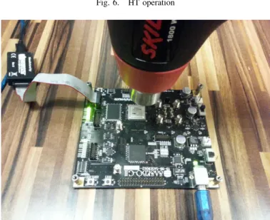
is high, i.e., when the monitor output is superior to 640 = b01010000000. This value corresponds to 42◦C. Therefore the trigger signal will be active when FPGA temperature is ≥ 42◦C. The trigger temperature can be easily changed according to the design under test. In our case study, a simple hair dryer of cost $5 is enough to heat the FPGA and reach this temperature. We assume that a system monitor is already instantiated in the design, to monitor device working conditions and the alarm is raised at a temperature ≥ 65◦C. In such a scenario, the HT trigger part does not need any extra logic and would result in a very low-cost HT example. The next section will describe the HT payload when it is activated thanks to this mechanism.
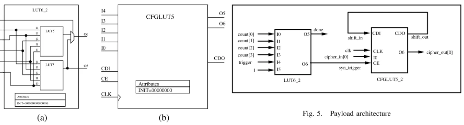
2) Payload Design: This section focuses on the payload design of the proposed HT. The architecture of the payload is shown in the Fig. 5. The objective of the payload is to
I4 I3 I2 I1 I0 LUT5 I4 I3 I2 I1 I0 LUT5 I5 I4 I3 I2 I1 I0 LUT6_2 O6 O5 Attributes INIT=0000000000000000 I4 I3 I2 I1 I0 CDI CE CLK O5 O6 CDO Attributes INIT=00000000 CFGLUT5 (a) (b)
Fig. 4. (a) LUT6 2 architecture. (b) CFGLUT architecture.
inject a fault in the 0thbit of the 8thround output after being
triggered.
For a stealthy hardware Trojan, payload must be as lightweight as possible. For this we have identified some of the LUTs which are already being used by the AES and replaced it by another LUT which performs the same operation of the former, along with the desired payload operation once being triggered.
For example, a LUT6 2 is used to generate encryption completion (done) signal, which becomes high when the 4 bit counter value becomes 11. The architecture of LUT6 2 is presented in Fig. 4(a). LUT6 2 is composed of two LUT5. Therefore it can be used as 5 input 2 output function or 6 input 1 output function. In this scenario, the corresponding LUT6 2 acts as a 4 input 1 output LUT. However, as we have stated before, a LUT6 2 can be configured as 5 input 2 output LUT. We have taken advantage of this feature and modified the LUT6 2 to 5 input 2 output LUT. In normal situation, LUT6 2 continues to perform as desired. But upon receiving the trigger (7th bit of temperature measurement output), it
generates a two clock cycle long sync trigger signal when counter value reaches 7 (counter value 7 indicates start of round 8 operation). This sync trigger signal is then passed to the CFGLUT5 2.
The CFGLUT5 2 presented in Fig. 4(b) is a runtime, dy-namically reconfigurable, 5-input look-up table (LUT) which is present in recent Xilinx FPGA. It enables the changing of the logical function of the LUT during circuit operation. Using the CDI pin, a new INIT value can be synchronously shifted in serially to change the logical function. The O6 output pin produces the logical output function, based on the current INIT value loaded into the LUT and the currently selected I0-I4 input pins. Optionally, we can use the O5 output in combination with the O6 output to create two individual 4-input functions sharing the same 4-inputs or a 5-4-input function and a 4-input function that uses a subset of the 5-input logic. This component occupies one of the four 6-input LUT components within a slice.
In our scenario, CFGLUT5 2 replaces a route-through LUT which acts as buffer in the AES design. In normal situa-tion, CFGLUT5 2 is configured as buffer (with INIT value
count[0] count[1] count[2] count[3] trigger 1 LUT6_2 I0 I1 I2 I3 I4 I5 O5 O6 I0 CLK CE CDI CDO O6 syn_trigger cipher_in[0] cipher_out[0] clk shift_in shift_out CFGLUT5_2 done
Fig. 5. Payload architecture
320hAAAAAAAA). However upon receiving the sync trigger signal as reconfiguration enable input (CE), CFGLUT5 2 acts like inverter (with INIT value 320h55555555) and injects the desired fault on the output. As sync trigger is two clock cycle long, after injecting one fault, CFGLUT5 2 switches back to its buffer operation and starts producing the correct output once again.
The HT operation is presented in the Fig. 6. The signals as used in the figure are as follows:
• CLK: clock signal used for both AES computation and
system monitor operation.
• Start signal: used to start each encryption.
• Round: the number of encryption round (10 rounds for one encryption in 128 bit AES).
• Trigger signal: 7th bit of temperature measurement
out-put.
• Syn trigger signal.
• Plain text: 128 bit plaintext data which apply at the AES input.
• Cipher text: 128 bit ciphertext data available at the AES output.
So the HT will be active when trigger signal is high and the AES operation is at 8thcomputation round. This HT allows to
generate two faulty ciphertext and perform Piret’s Fault Attack to retrieve the secret key value. To do this, we first apply the plaintext P 1 to obtain the good ciphertext C1. Then we keep the same plaintext P 1 at the AES input while heating the FPGA with the hairdryer and observe the output ciphertext. If the ciphertext is different than C1, it means that HT is active (FPGA die temperature is higher than 42◦C) and injects faults in the encryption. So we obtained the bad ciphertext C01. Then we perform the same process for another plaintext P 2 to obtain the good ciphertext C2 and the bad ciphertext C02. With these 4 ciphertexts, we were able to recover the secret key of the implemented AES.
AES implementation on Virtex-5 platform of SASEBO-GII board needs 1594 LUTs and 260 flip-flops. The maximum op-erating frequency supported by this implementation is 212.85 MHz. The overhead of the developed Trojan Payload is zero as we just modify the existing components of the AES design to construct the Trojan payload. Please note that zero overhead is important because both negative and positive overhead HT can be detected by gate count verification.
00000 00000 00000 11111 11111 11111 00000000000000000000000 00000000000000000000000 00000000000000000000000 00000000000000000000000 11111111111111111111111 11111111111111111111111 11111111111111111111111 11111111111111111111111 CLK Start Syn_trigger Trigger Round Rn 0 Rn 0 Rn 8 Rn 9 Rn 0 Rn 0 Rn 0 Rn 8 Rn 9 Rn 0 GOOD C1 P1 Plain text
Cipher text BAD C’1
Fig. 6. HT operation
Fig. 7. Piret Trojan test platform
The Fig. 7 presents the test platform for Piret HT. We obtained the secret key by heating the circuit during 4 minutes. C. Case Study 2: Side-Channel Hardware Trojan
In this part, we provide a case study using the probe sensor, as described in the Sec. III-B for the HT insertion. Sometimes designer deploy custom designed sensors instead of using commercially available options. In the following case study, we use one such sensor for HT insertion. We have developed a stealthy HT circuitry on a protected ECDSA module. A probe sensor will be used for both HT trigger and payload part 8 using the calibration ring oscillator and LC coil. We use the Xilinx Virtex-5 FPGA as test platform for this case study . The LC coil was implemented using Super Long Lines (SLL,VLONG,HLONG) and manually routed. One can expect to get a higher inductive coupling between the coil and the EM probe on ASIC due to the presence of buffers and switchbox interconnects on FPGA that cuts the inductive load of the LC coil. However, even if the underling phenomenon that involve the leakage of the LC-coil oscillation frequency is not exactly the same on ASIC and FPGA, an FPGA is enough to illustrate our proof of concept HT. The goal of the side-channel Hardware Trojan is to leak ECDSA secret scalar which is
Fig. 8. HT on probe sensor
private key via Electromagnetic emanation of LC coil. The following subsections will describe this HT, which incurs an extremely small footprint without modifying the circuit IO.
1) Side Channel HT Trigger: As shown in Fig. 8, the calibration ring oscillator (RO) will be exploited for HT trigger part. In the probe sensor system, this RO is used as PVT (process, voltage and temperature) monitor for calibration. Therefore, we can control the value of the RO with these environment parameters and use them as hidden inputs for HT activation. A 10 bits counter is already present in the coun-termeasure to evaluate the oscillation frequency of calibration RO. At normal PVT, the RO oscillates at 200 MHz hence the 10 bit counter output is 200 = 0xEC = b00011101100. The Side Channel HT will probe directly the 4th bit of the counter output. It will be activated when bit4 is reset. This will typically occur when the temperature is greater than 60◦C. Therefore the HT trigger part will induce close to zero overhead in term of logic resources utilization (Fig. 9).
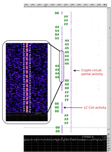
2) Side Channel HT Payload: As shown in Fig. 8, we exploit directly the LC coil of probe sensor for leaking the secret scalar K of a protected embedded hardware ECDSA module. The principle is simple. In the ECDSA cryptographic module, each bit of the scalar is tested sequentially when the ECC scalar product (Blinded Montgomery Ladder in our case) K × P is performed. The HT payload will read directly the test bit of scalar module and leak it via LC coil. The final architecture of Side Channel HT is presented in Fig. 9. When HT is activated, the LC coil will serve as simple ASK (Amplitude Shift Keying) modulator and transmitter with very high bandwidth efficiency. More precisely, it will oscillate at 2 different frequencies ( 0 MHz or its normal frequency) depending on the scalar bit value. So the scalar bit value can be extracted by simply monitoring the Power Spectral Density (PSD) of the Electromagnetic field of the circuit .
The test platform for the side channel HT is composed of 11:
• FF324 Virtex 5 FPGA test board used to implement probe
sensor and Side Channel HT.
• Langer 5-2 probe used to monitor the oscillation
fre-quency of LC.
Calibration RO b255 b254 b253
...
b0 LC coil P 64 ECC (M.Ladder) Scalar Mult 10 Bit Counter LC control part LC resetSide Channel HT
Original Circuit
Scalar(K)
4thbit
Fig. 9. Side Channel HT architecture
PSD.
The Fig. 10 presents the PSD of LC coil when the side channel HT is activated. We can notice that the scalar values are well leaked by the LC coil. To recover the ECDSA secret scalar, we just need to acquire a single EM trace of LC coil. Then we perform the Short Term Fast Fourier Transform (ST-FFT) on this EM trace. The secret scalar can then be directly read from the ST-FFT in the frequency band of interest (236M Hz in our case of study). The Fig 13 shows the result of our Side-Channel HT. The Fig 12 shows the EM trace acquired during 1ms. This acquisition time corresponds to the execution time of the scalar product operation. It ensure that all secret scalar bits are included in the EM trace. By observing the EM trace, the secret scalar cannot be extracted. So it is difficult for tester/user to detect the HT activity. But using ST-FFT plot, when HT is triggered, we can easily and quickly (less than 1 second) recover the secret scalar even with poor Signal to Noise Ratio (SNR) because the oscillator frequency is well separated from others spectral components. In our case study, we use “0xFFFFFF000000FFFFFF000000FFFFFF000000 0x4444444444444404545445584544” as ECDSA secret scalar. The Fig 13 shows the ST-FFT of EM trace presented in Fig 12. When the magnitude of the signal in the time-space plan around 233M Hz is not zero, the scalar bit is reset, else the scalar bit is set. We notice that the ECDSA secret is clearly distinguishable from the noise and others components .
Please note that our tests where performed using a near field probe. Even with such a probe we where able to retrieve the secrete by positioning the probe at 2cm away from the target. At such a distance, the EM field micro-probe detection countermeasure is ineffective while the attacker can easily read the modulated secret information in less than 1s with a single trace.
(a) (b)
Fig. 10. LC coil activity spectrum: (a) without HT activation, (b) with HT activation.
Fig. 11. Side-Channel Trojan test platform
V. DISCUSSION
In this paper, we presented how integrated sensors can be exploited for HT insertion. In the case study, we use the temperature as hidden input for HT activation. For the Piret HT, the chosen temperature is 42◦C and for the Side Channel HT, the chosen temperature is 60◦C. These values are chosen just for our proof of concept. But we can choose another temperatures which are nearly never used during the test time or utilization time for example a negative temperature. We can even combine the temperature bits with another internal signal with very small footprint to decrease the HT accidental activation probability during test time. And for the
Side Channel HT, in many case, users can not detect it even triggered.
For the Side-Channel HT, we use the Amplitude-Shift-Keying(ASK) modulation to leak the ECDSA secret scalar. However, we can also use a frequency other than 0M Hz to encode the ECDSA scalar bits ’1’ (FSK modulation). It can be done by simply changing the LUT configuration used for LC coil calibration [6] (hence reducing the SCA HT payload). Thus even if SCA HT is constantly activated (no Trigger Part), it will be still extremely difficult to detect its activity without the knowledge of the trojan structure.
In this paper, we show environment parameters, which are not checked during test time, can be exploited for HT insertion. Therefore, the functional test must be redefined in order to take into account these parameters.
For our research direction, we aim to detect and prevent these HTs. One solution could be to apply the “encoded circuit” in [3]. This method consist in encoding and masking all internal registers (including control and data registers). It can ensure that the secret information will be dynamically encoded and masked with a random mask in each cycle clock. So the value leaked by LC coil will be masked and encoded. Therefore the attacker can not recover the secret.
VI. CONCLUSION
Nowadays, hardware Trojan have become a real problem for embedded systems. In this paper, we present new HT designs which exploit directly the integrated sensors (used to counter physical attack) as their trigger and payload parts. The first HT based on the System Monitor on FPGA Virtex 5 to activate its malicious function. Once activated, it will perform Piret attack to leak the AES secret key. Insertion of this HT on FPGA Virtex 5 requires zero overhead by modifying 2 existing LUTs. In the second case study, we demonstrate a Side-Channel HT insertion using custom sensor for detecting EM probes [6] as both trigger and payload part. This HT allows to leak ECDSA secret scalar via EM emanation of LC coil (used to detect micro-probe presence). The experiment was done on FPGA Virtex 5. The SCA HT is implemented with very low overhead (just 2 standard gates).
The purpose of this paper is to demonstrate that Integrated Sensors can be used as a backdoor for HT insertions. That is why, a new test methodology must be redefined to take into account this threat. For the future work, we aim to detect and prevent these kinds of HTs.
REFERENCES
[1] Miron Abramovici and Paul Bradley. Integrated circuit security: new threats and solutions. In Frederick T. Sheldon, Greg Peterson, Axel W. Krings, Robert K. Abercrombie, and Ali Mili, editors, CSIIRW, page 55. ACM, 2009.
[2] M. Banga and M.S. Hsiao. ODETTE: A non-scan design-for-test
methodology for Trojan detection in ICs. In Hardware-Oriented Security and Trust (HOST), 2011 IEEE International Symposium on, pages 18– 23, June 2011.
[3] Shivam Bhasin, Jean-Luc Danger, Sylvain Guilley, Zakaria Najm, and
Xuan Thuy Ngo. Linear Complementary Dual Code Improvement
to Strengthen Encoded Circuit Against Hardware Trojan Horses. In 2015 IEEE International Symposium on Hardware-Oriented Security and Trust, HOST 2015, McLean, VA, USA, May 5-7 2015.
Frequency (MHz)
T
ime (ms)
Fig. 13. Key extraction: EM trace ST-FFT
[4] Shivam Bhasin, Jean-Luc Danger, Sylvain Guilley, Thuy Ngo, and Laurent Sauvage. Hardware Trojan Horses in Cryptographic IP Cores. In FDTC, pages 15–29, August 20 2013. Santa Barbara, CA, USA.
[5] Gedare Bloom, Bhagirath Narahari, and Rahul Simha. Os support
for detecting trojan circuit attacks. In Proceedings of the 2009 IEEE International Workshop on Hardware-Oriented Security and Trust, HST ’09, pages 100–103, Washington, DC, USA, 2009. IEEE Computer Society.
[6] Naofumi Homma, Yu-ichi Hayashi, Noriyuki Miura, Daisuke Fujimoto,
Daichi Tanaka, Makoto Nagata, and Takafumi Aoki. EM Attack
Is Non-invasive? - Design Methodology and Validity Verification of EM Attack Sensor. In Lejla Batina and Matthew Robshaw, editors, Cryptographic Hardware and Embedded Systems – CHES 2014, volume 8731 of Lecture Notes in Computer Science, pages 1–16. Springer Berlin Heidelberg, 2014.
[7] Yier Jin, Nathan Kupp, and Yiorgos Makris. Experiences in Hardware Trojan Design and Implementation. In Proceedings of the 2009 IEEE In-ternational Workshop on Hardware-Oriented Security and Trust, HOST ’09, pages 50–57, Washington, DC, USA, 2009. IEEE Computer Society. [8] Samuel T. King, Joseph Tucek, Anthony Cozzie, Chris Grier, Weihang Jiang, and Yuanyuan Zhou. Designing and implementing malicious hardware. In Proceedings of the 1st Usenix Workshop on Large-Scale Exploits and Emergent Threats, LEET’08, pages 5:1–5:8, Berkeley, CA, USA, 2008. USENIX Association.
[9] Gilles Piret and Jean-Jacques Quisquater. A Differential Fault Attack Technique against SPN Structures, with Application to the AES and KHAZAD. In CHES, volume 2779 of LNCS, pages 77–88. Springer, September 2003. Cologne, Germany.
[10] Xilinx. Virtex-5 FPGA System Monitor. http://www-inst.eecs.berkeley. edu/∼cs150/fa13/resources/ug192.pdf.
![Fig. 1. FPGA Xilinx System monitor architecture [10]](https://thumb-eu.123doks.com/thumbv2/123doknet/12294435.323547/4.918.467.847.80.281/fig-fpga-xilinx-system-monitor-architecture.webp)
![Fig. 3. Microprobe Sensor Architecture [6]](https://thumb-eu.123doks.com/thumbv2/123doknet/12294435.323547/5.918.84.458.79.425/fig-microprobe-sensor-architecture.webp)