HAL Id: hal-01183803
https://hal.archives-ouvertes.fr/hal-01183803
Submitted on 11 Aug 2015
HAL is a multi-disciplinary open access
archive for the deposit and dissemination of
sci-entific research documents, whether they are
pub-lished or not. The documents may come from
teaching and research institutions in France or
abroad, or from public or private research centers.
L’archive ouverte pluridisciplinaire HAL, est
destinée au dépôt et à la diffusion de documents
scientifiques de niveau recherche, publiés ou non,
émanant des établissements d’enseignement et de
recherche français ou étrangers, des laboratoires
publics ou privés.
Multi-band OFDM for optical networking
Sofiene Blouza, Julie Karaki, Nicolas Brochier, Esther Le Rouzic, Erwan
Pincemin, Bernard Cousin
To cite this version:
Sofiene Blouza, Julie Karaki, Nicolas Brochier, Esther Le Rouzic, Erwan Pincemin, et al.. Multi-band
OFDM for optical networking. EuroCon 2011, Conference on telecommunications, Apr 2011, Lisbon,
Portugal. �10.1109/EUROCON.2011.5929191�. �hal-01183803�
Multi-Band OFDM for Optical Networking
Sofiene Blouza, Julie Karaki, Nicolas Brochier,
Esther Le Rouzic, Erwan Pincemin
Orange Labs 2 Av. Pierre Marzin
22300 Lannion
Bernard Cousin
University of Rennes 1, IRISACampus de Beaulieu 35042 Rennes [email protected]
Abstract— In this paper, we present a novel networking
technique based on optical Multi-Band Orthogonal Frequency Division Multiplexing (MB-OFDM). We highlight the interesting features of the solution with respect to existing ones (fully opaque optical networks and transparent networks) for optical metro and core networks. We show that under certain traffic condition MB-OFDM may offer useful flexibility in the context of increasing wavelength bit rates.
Keywords: multi-bands orthogonal frequency division multiplexing; optical networking; reconfigurable optical add and drop multiplexer
I. INTRODUCTION
In the last years, the overall traffic in core and metro networks has increased by 45% per year on average [1] partly driven by the increase of multimedia contents and peer to peer applications. To catch up with this increase, link capacity of core and metro optical networks have grown up to several terabit/s per fiber pair [2] mainly allowed by the improvement of transmission system performances. To benefit from the network transparency and thus reduce the overall cost and consumption of the networks [3], Reconfigurable Optical Add and Drop Multiplexers (ROADM) are now widely deployed.
These all-optical transmission techniques allow managing and switching full WDM channels without requiring Optical to Electrical and Electrical to Optical interfaces (O-E-O). However the use of an electrical aggregation layer remains mandatory for finer granularity than the capacity of optical channels.
After increasing the overall number of WDM channels up to more than one hundred per fiber, the race for capacity now goes through an increase of the capacity per channels and the 100 Gbit/s per WDM channel is becoming the next standard for optical transmission systems [4]. As a result, the minimum granularity (WDM channel) managed by ROADMs is greatly increased, which may accentuate the needs for electrical switching leading to an important growth in power consumption.
In this context, a new approach based on the multi-bands Orthogonal Frequency Division Multiplexing (MB-OFDM) modulation techniques can offer an interesting trade-off between capacity increase and electrical consumption. Indeed the main innovation of this technique is its capability to optically switch at the sub-wavelength granularities thanks to the multi-band structure of the WDM channel [5].
In this paper, we present the concept of MB-OFDM for optical networking and analyze its potential compared to trend-setting technologies. This paper is ordered as follows. The second section introduces the technological principles of MB-OFDM technique. In the third section the different types of flexibility offered by the MB-OFDM are described and modeled. Finally, in a fourth section, we compare three simple scenarios, purely opaque node, purely transparent node and MB-OFDM node in terms of optical WDM channels and electrical interfaces numbers.
II. MB-OFDM
MB-OFDM modulation has already been used in wireless meshed networks [6]. In this paper we focus on a specific technique applied to optical communications.
A. Optical OFDM Basics
The basic principle of orthogonal frequency division multiplexing (OFDM) technique is to split a high-rate data stream into a number of lower-rate data streams that are transmitted simultaneously over a number of subcarriers. The main feature of OFDM resides in the orthogonality of its subcarriers. It eliminates the inter-carrier interference and provides a high spectral efficiency by allowing spectral overlapping. To maintain this orthogonality and thus to eliminate the inter-symbol interference due to linear optical propagation impairments such as chromatic dispersion (CD) and polarization mode dispersion (PMD) a cyclic prefix is added to each OFDM symbol. This advantageously avoids external optical or electrical compensation components which otherwise would be required to overcome deleterious impact of CD and PMD.
B. MB-OFDM Basics
Compared to single band OFDM, MB-OFDM is based on the division of the WDM channel spectrum into several independent OFDM sub-bands [7]. Each sub-band bij has its
own optical frequency carriers IFij as shown in fig. 1 where i, j
are the sub-band and channel number respectively. MB-OFDM also overcomes Digital to Analog Converters (DAC) and Analog to Digital Converters (ADC) frequency limitations when bit rate increases (discussed in Section C). However the architecture of the MB-OFDM transponder remains complex because it requires several single band generation and reception.
The work described in this paper was carried out with the support of the 100G FLEX project funded under the Ninth French FUI Framework.
Figure 1. Optical spectra of MB-OFDM
C. Performances
The total data rate R of an OFDM signal can be expressed as a function of its bandwidth B and constellation order M:
R=B*log2 (M) (1)
The bandwidth B and constellation order M of the OFDM signal are limited in particular by the current performances of the DAC and ADC. Consequently, a single-band approach to generate data rate up to 100 Gbit/s and higher (400 Gbit/s and 1 Tbit/s) is not possible today. The multi-band OFDM technique overcomes this limitation by considerably relaxing the constraints on the key components that are DAC and ADC while providing data rate flexibility in terms of transmission conditions.
We should mention here that the minimum possible channel spacing today for 100 Gbit/s bit rate is 50 GHz leading to 2 bit/s/Hz spectral efficiency. Even if evolution towards higher bit rates implies larger channel spacings (e-g. 75 GHz for 400 Gbit/s and 150 GHz for 1 Tbit/s data rates), the OFDM technique allows to significantly increase the overall capacity of the fiber with better performances than the single carrier solutions.
Furthermore, MB-OFDM offers flexibility on sub-band data rates. Indeed as shown in equation (1), the variation of the constellation order M allows to adapt the data rate R of each sub-band. This flexibility is in particular limited by the minimum signal to noise ratio required to recover the data. For short distances, high constellation order can be used while a lower constellation order is required for long haul transmission. Also variation of the bandwidth B is possible under the limitation fixed by DACs/ADCs.
III. NETWORKING WITH SUB-BANDOFDM
We now consider MB-OFDM as a networking technique. For this purpose we consider a simplified model for the MB-OFDM transponder as well as for the switching nodes. The characteristics of the bands (number, data rate…) are set according to the technological limits presented in section II. Beyond the sub-wavelength optical switching capability of the technique, there are many flexibilities that distinguish MB-OFDM from other optical switching technologies.
A. OFDM SUB-BAND switching
Similarly to waveband and wavelength switching [8], OFDM band switching consists in grouping different sub-bands onto a single wavelength. Multiple requests that have a common segment or path can be grouped onto the same wavelength without optical to electrical conversion. The advantage of sub-band switching is switching at finer granularities than the wavelength granularity whilst remaining in the optical domain. This can be done thanks to optical filters, Wavelength Selective Switch (WSS) [5].
The sub-band switching function is represented by: {bij}{Fl} Æ {bi’j’}{Fl’} (2)
That means that a set of sub-bands {bij} of fibers {Fl} is
switched into a set of sub-bands {bi’j’} of fibers {Fl’}.
The complexity of the sub-band aggregation depends on the position of the sub-bands in the WDM channels. Several functionalities should be added to MB-OFDM nodes to remove the constraints on the spectral position of sub-bands to aggregate. In this formula we extract three important cases:
1) Wavelength continuity (j=j’and i≠i’): The wavelength
continuity constraint implies sub-band continuity and requires that sub-bands grouping shall be limited to sub-bands having the same channel. Moreover, sub-band grouping is limited to the condition of the sub-bands availability in the output channel (to avoid sub-band contention).
2) Wavelength conversion (j≠j’): As for traditional
wavelength switched networks, wavelength contention can occur. A solution consists in using wavelength converters [9]. In this case, sub-bands of different wavelengths can be grouped as shown in Fig. 2 where the wavelenght conversion of λi’ to λi is required to group b2,i and b3,i’on the same fiber F3.
Figure 2. Sub-band switching with wavelength conversion
3) Sub-band conversion (i≠i’): Compared to wavelength
conversion that converts all the sub-bands of a wavelength, sub-band conversion consists in converting any sub-band to any other sub-band even in the same wavelength (this latter is called sub-band translation). That can be realized thanks to wavelength converter or thanks to optical or electrical up/down conversion [10].
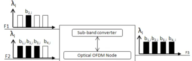
Sub-band switching may be viewed as an optical aggregation technique limited at the sub-band granularity. An example of sub-band conversion is illustrated in Fig. 3. In this example, the sub-band b2,i of fiber F1 is converted into b4,i. After that, it
is aggregated in λi of fiber F3 with sub-bands of λi of fiber F2.
Figure 3. Example of sub-band switching with sub-band conversion
B. Edge aggregation
Several possibilities can be proposed to aggregate traffic in the edge nodes.
• A single service uses a single sub-band. This solution does not require electrical aggregation, but implies to reserve the entire sub-band for one service whatever the bandwidth of the service.
• A single service uses a group of sub-bands. When the bandwidth of the service is larger than the sub-band capacity, it can be transported on several sub-bands. • Similarly to single wavelength transponders (legacy),
several services can be aggregated into a same sub-band or a group of sub-sub-bands. To avoid electrical conversion in the switching nodes, the aggregated services must have the same source and destination.
C. Bit-rate adaptation
A specificity of OFDM modulation is its adaptability to the physical transmission condition (section II). Let us recall that the sub-band optical reach depends on the bit rate carried by this sub-band. A service with a given data rate having to be delivered at the distance exceeding the maximum reach of the sub-bands, can be split between two or more sub-bands with reduced bit-rate. This is an alternative solution to regeneration [11]. Reversely, service to be delivered at a very short reach can benefit from the highest bit rate of the sub-band.
D. Number of sub-bands
The variation of the number of sub-bands offers also an interesting flexibility. For example, the number of sub-bands in a wavelength can be increased to aggregate a high number of services and avoid the use of another wavelength. The number of sub-bands can also be varied to have finer granularities, still keeping high bit rates of the channel. In this paper we don’t consider this adaptability because of technical challenges.
IV. PRELIMINARY EVALUATION OF MULTI-BAND OFDM NETWORKING
In order to evaluate the interest of MB-OFDM in terms of potential cost savings and energy consumption, we compare three simple scenarios: purely transparent optical node, purely opaque node and MB-OFDM node. For this purpose we use the number of required WDM channels and the number of electrical interfaces, the two most interesting comparison criteria relating to cost and energy consumption.
A. Assumptions
For these preliminary studies, all scenarios are evaluated on a single node. We are well-aware of the impact of wavelength routing when a network with many nodes is considered. However we think that a preliminary study on a single node will achieve sufficient interesting results, because we anticipate that MB-OFDM solution will provide better results when a full network topology is modeled.
Traffic entering into the node can be added, dropped or can transit through the node. Links connected to the node are bidirectional.
S1: Purely transparent optical node scenario: Purely
transparent node is a node where O-E-O conversions are not allowed. Traffic in transit can not share the same channel as
add or drop traffic. This type of node does not require any electrical interface (they have only optical interfaces).
S2: Purely opaque node scenario: In purely opaque node,
O-E-O conversions can be used to aggregate transit and add traffic in the same channel or disaggregate transit and drop traffic from a given channel. Transit traffic is systematically converted into electrical signals and back to optical signals thanks to electrical interfaces. Here we have total flexibility to group traffic.
S3: MB-OFDM node scenario: In this study we suppose
that each MB-OFDM channel is composed of nb = 5 sub-bands.
Each sub-band transports a fixed Db = 20 Gbit/s bit rate. We
consider sub-bands switching functionality and we suppose that a single request can use a group of sub-bands if the requested data rate exceeds the maximum capacity of 1 sub-band. For example, we use 3 sub-bands for a 50 Gbit/s request. Sub-bands in transit are transparently switched in the node and do not cross any O-E-O interface.
B. Comparison criteria
Scenario S1 has the advantage of reducing costly O-E-O processing for transit traffic compared to S2 but requires more WDM channels meaning more electronic interfaces for add and drop traffic than S2. Scenario S3 offers a trade-off between both extreme S1 and S2 cases. We thus calculate the number of required WDM channels and the number of electrical interfaces, at a given load for S1, S2 and S3 scenarios. We use the following definitions:
Let {ai, 0≤i≤A} be the set of requests to be inserted in the
node towards a given egress direction; {tj, 0≤j≤T} the set of
traffic in transit; n the number of WDM channels in a fiber; D the bit rate per channel; Db the bit rate per sub-band. We note
that D = nb.Db by definition. The data rate of ai is arbitrarily
comprised between 0 Gbit/s and D in this paper.
1) Number of used channels:
For the sake of simplicity we only consider transit and add traffic as dropped traffic is an "add" in an upstream node. In the fully transparent node (S1), the number of used channels per
egress is
NC(S1) = Σ ⎡ai/D⎤ + Σ ⎡tj/D⎤ (3)
In the fully opaque node (S2) the number of used channels
per egress is:
NC(S2) = ⎡Σai/D+Σtj/D⎤ (4)
The number of used channels per egress for S3 is:
NC(S3) = ⎡1/nb Σ ⎡ai/Db⎤ +1/nbΣ ⎡tj/Db⎤ ⎤ (5)
,with the hypothesis that all the requests are grouped in a minimum number of channels independently from their respective routes.
2) Number of electrical interfaces:
Let {dk, 0≤k≤Δ} be the set of requests to be dropped in the
node from a given ingress. We arbitrarily count as one interface one O-E conversion or one E-O conversion, a transponder counts for 2 interfaces.
In fully transparent nodes, electrical interfaces are only used for added and dropped traffic. The number of electrical interfaces for S1 is thus:
NE(S1) = Σ ⎡ai/D⎤ + Σ ⎡dk/D⎤ (6)
In fully opaque nodes, all the traffic is converted in the electrical domain. Added and dropped traffic requires the same number of electrical interfaces as fully transparent node NE(S1)
on add/drop side of the node. On the egress the number of interfaces corresponds to the number of channels NC(S2),
while the number of ingress interfaces corresponds to the number of ingress channels grouping drop and transit traffic is: NE(S2) = Σ ⎡ai/D⎤ + Σ ⎡dk/D⎤ + ⎡Σ ai/D + Σ tj/D⎤ +
⎡Σ dk/D + Σ tj/D⎤ (7)
Like in purely transparent node, transit traffic in MB-OFDM node is not converted in the electrical domain. The number of electrical interfaces is:
NE(S3) = ⎡Σ ai/Db + Σ dk/Db⎤ (8)
To account for OFDM complexity we consider that a MB-OFDM transponder has 2.nb interfaces.
C. Discussion
We first note that:
NC(S2) ≤ NC(S3) ≤ NC(S1) (9)
As expected, S2 offers the minimum number of channels and S3 a possible trade-off between S1 and S2. This is explained by the fact that S2 optimizes the resource occupation thanks to the fine granularities processed in the opaque node.
Then we note that:
NE(S1) ≤ NE(S2) and NE(S1) ≤ NE(S3) (10)
This confirms that S1 offers the minimum number of electrical interfaces. The comparison between S2 and S3 depends on the numerical application for D, Db, ai, dk and tj.
For example if transit traffic is null, as soon as the requested bit rate ai strictly exceeds Db, NE(S2) ≤ NE(S3). If
add/drop traffic is null, then NE(S3) ≤ NE(S2).
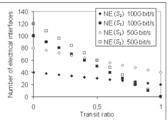
Figure 4. Evolution of NE(S2) and NE(S3) as a function of transit ratio.
Fig. 4 depicts the evolution of NE(S2) and NE(S3) as a
function of transit ratio Σ tj / (Σ ai + Σ tj) in the particular case
where each ai, dk and tj all requires 100 Gbit/s (or 50 Gbit/s)
data rate and Σ ai = Σ dk with D = 100 Gbit/s (the next standard
for optical transmission), and for a constant load (2*[Σ ai + Σ tj]
= Cste).
We note that the interest for MB-OFDM decreases with the channel occupation but increases with the transit percentage. This is due to the fact that when channels are fully occupied sub-band grouping is not useful and when transit traffic is high MB-OFDM fully benefits from transparency.
V. CONCLUSION
This paper presents MB-OFDM applied to optical networking concept. The flexibility offered by this technique is discussed compared to two extreme scenarios: fully transparent and fully opaque switching nodes. In particular we demonstrate that the use of sub-band switching allows saving on the number of O-E-O interfaces and thus is an interesting candidate for optical networks in the context of traffic increase and energy scarcity. In future work, we will study the blocking probability applied to generic network architectures using such MB-OFDM nodes with different types of traffic.
ACKNOWLEDGMENT
Authors would like to thank Jelena PESIC for fruitful discussion and support.
REFERENCES
[1] E. Le Rouzic, “Network Evolution and the Impact in Core Networks,” ECOC, Symposium on Optical Networking for Future Broadband Internet Services, 2010.
[2] S. Bigo, G. Bellotti, O. Rival, “After Today’s 100Gbit/s transmission in optical networks”, ECOC, Symposium Towards 1000Gb, 2010. [3] A. Morea, H. Nakajima, L. Chacon, E. Le Rouzic, B Decocq, J-P.
Sebille, "Impact of the reach of WDM systems and traffic volume on the network resources and cost of translucent optical transport networks", International Conference on Transparent Optical Networks, 2004. [4] M. Carroll, J. Roese,T. Ohara, “The operator's view of OTN evolution”,
Communications Magazine, IEEE, Issue 9, Vol. 48, 2010.
[5] R. Dischler, F. Buchali, A. Klekamp, “Demonstration of bite rate variable ROADM functionality on an optical OFDM superchannel”, Conf. on Optical Fiber Communication, 2010.
[6] M. Keskinoz, O. Gurbuz, E. Masazade , “Cross-layer enhanced time scheduling for multi-band OFDM UWB networks" Journal on Wireless Networks, vol. 16, Issue. 3,p. 863-873, April 2010.
[7] S.L. Jansen, I.Morita, H. Tanaka, “10*121.9 Gbps PDM-OFDM transmission with 2 bit/s/Hz spectral efficiency over 1000 km of SSMF”, Conf. on Optical Fiber Communication, 2008.
[8] A. Todimala, B. Ramamurthy, “Algorithms for intermediate waveband switching in optical WDM mesh networks”, High-Speed Networks Workshop, p. 21 - 25 , 2007.
[9] B. Ramamurthy, B. Mukherjee, “Wavelength conversion in WDM networking," IEEE Journal on Selected Areas in Communications, vol. 16, no. 7, pp. 1061-1073, Sep. 1998.
[10] Y. Ma, Q. Yang, Y. Tang, S. Chen ,W. Shieh,” 1-Tb/s per channel coherent optical OFDM transmission with subwavelength bandwidth access”, Conf. on Optical Fiber Communication, 2009.
[11] A. Klekamp, O. Rival, A. Morea, R. Dischler, F. Buchali, “Transparent WDM network with bitrate tunable optical OFDM transponders”, Conf. on Optical Fiber Communication, 2010.