A COMPARATIVE STUDY OF STRUCTURAL MATERIAL
FOR DOME CONSTRUCTION
MASSACHUSETTS INSTITUTE
BY
OF TECHNOLOGYCHUN WAI HUNG
JUL 10 2009
Bachelor of Engineering, Civil Engineering
LIBRARIES
The Cooper Union for the Advancement of Science and Art, 2008Submitted to the Department of Civil and Environmental Engineering in Partial Fulfillment of the Requirements for the Degree of
Master of Engineering in Civil and Environmental Engineering
at the
MASSACHUSETTS INSTITUTE OF TECHNOLOGY ARCHVES
JUNE 2009
@ 2009 Chun Wai Hung. All rights reserved
The author hereby grants to MIT permission to reproduce and to distribute publicly paper and electronic copies of this thesis document in whole or in part in any medium now
known or hereafter created.
Signature of Author:
bepartment of Civil and Environment 1 Engineering May 8th, 2009
Certified by:
Sb Jerome J. Connor
Professor of Civil and Environmental Engineering Thesis Supervisor
Accepted by:
Daniele Veneziano Chairman, Departmental Committee for Graduate Students
A COMPARATIVE STUDY OF STRUCTURAL MATERIAL
FOR DOME CONSTRUCTION
By
Chun Wai Hung
Submitted to the Department of Civil and Environmental Engineering on May 8th, 2009 in partial fulfillment of the
requirements for the Degree of Master of Engineering in Civil and Environmental Engineering.
ABSTRACT
Unobstructed free space is a pervasive goal in the design of structures intended to provide shelter and protection. This is especially essential for venues such as athletics, spectator activities, and large congregations. The need for such space is constrained by structural feasibility and costs of material and construction. Space structures, and more specifically, the dome structural system is an efficient way to achieve this desired goal. The benefit of domes is that it can be shaped in such a way so that the members are only under axial
stresses. Typical construction materials for large span braced domes are dominated by metallic alloys such as steel and aluminum due to their relatively high strength to weight ratio. Timber domes are observed much less frequently. However, recently there is a development of an increase in the use of timber as a structural material due to its potential
as a sustainable and more environmental option. Trees can be harvested in a much more sustainable manner than materials such as steel. The aim of this thesis is to compare the advantages and disadvantages of the design and construction of a typical dome structure using differing structural materials of timber and steel. A lamella dome system with the
same dimensions and layout was used for the analysis and design of both options. Parameters such as the total self-weight of the structural members, cost, deflection, durability, and sustainability were compared and discussed.
Thesis Supervisor: Jerome J. Connor
ACKNOWLEDGMENTS
I would like to thank Professor Jerome J. Connor for his guidance and mentorship throughout my time at MIT and for the development of this thesis.
The Master of Engineering class has been among the best group of individuals I have ever met.
TABLE
OF
CONTENTS
1 INTRODUCTION ...
13-2 GENERAL OVERVIEW- SPACE STRUCTURES/DOMES ...- 15
-2 .1 D O M E S ... 16
-2.1.1 HISTORY OF DOMES ... 16
-2.1.2 NOTABLE ANCIENT DOMES ...- 18
-2.1.3 PROPERTIES OF DOMES ...
20-2.1.4 OVERVIEW OF DOME CONSTRUCTION MATERIALS ...-
20-3. B RA C ED D O M ES ... ...- 23
-3.1 RIBBED DOMES ... 23
-3.1.1 BRACED RIB DOME ...
24-3.1.2 SOLID RIB DOME ...-
25-3.2 SCHWEDLER DOMES ...-
26-3.3 STIFF-JOINTED FRAMED DOMES ...-
27-3.4 PLATE TYPE DOMES ... 28
-3.5 NETWORK DOMES ...
29-3.6 ZIMMERMAN DOMES ...
29-3.7 LAM ELLA DO M ES ... 30
-3.7.1 CURVILINEAR LAM ELLA... 31
-3.7.2 PARALLEL LAMELLA ... 32-3.8 GEODESIC DOMES ...- 32-4 T IM B E R ... ... 35 -4.1 STRUCTURAL TIMBER ... 37 -4.1.1 DISADVANTAGES OF WOOD ... 37-4.1.2 ADVANTAGES OF WOOD... 37-4.2 PROPERTIES OF WOOD ...- 38
-4.3 FACTORS AFFECTING STRENGTH AND STIFFNESS ...-
40-4.3.1 MOISTURE CONTENT... 40 -4.3.2 SPECIFIC GRAVITY ... 40 -4.3.3 DURATION OF LOADING ... ... 41 -4 .3 .-4 D E F E C T S ... 42 -4.3.5 TEMPERATURE EFFECTS ... ... 45-4.4 DURABILITY OF WOOD ... 45
-4.4.1 DECAY, MOLDS, AND STAINS...
45-4.4.2 INSECT ATTACKS ... 46
-4.4.3 CHEMICAL RESISTANCE ... 47
-4.4.4 FIRE CO NCERNS ... 47
-5 MODEL DEFINITION ... 49
-5.1 MODEL TYPE AND GEOMETRY ... 49
-5.2 SAP2000 MODEL ANALYSIS ... 52
-5 .3 LO A D IN G S ... ... 54
-5.3.1 DEAD LOADS ...
54-5.3.2 LIVE LOADS ...-
54-5.3.3 SNOW LOAD ...
55-5.3.5 SEISMIC LOAD ... 60
6 DESIGN AND ANALYSIS ...- 61
6.1 TIMBER DESIGN ... - 61
6.1.1 DESIGN OF TIMBER COMPRESSION MEMBERS...- 62
6.1.2 DESIGN OF TIMBER TENSION MEMBERS ...- 66
6.1.3 DESIGN OF TIMBER DOME IN RISA 3-D ...- 66
6.2 STEEL DESIGN ... 68
6.3 COMPARISONS ... 69
6.3.1 W E IG H T ... 69
6.3.2 DEFLECTION ... 69
6.3.3 MATERIAL COST. ... - 71
6.3.4 SUSTAINABILITY/ ENVIRONMENTAL IMPACT...- 73
7 CONCLUSIONS ... 77
8 R EFE R E N C ES ... 79
LIST OF FIGURES
Figure 1: The Pantheon ... ....-
18-Figure 2: St. Sophia...
-18-Figure 3: Typical Braced Dome Sections ...- 24
-Figure 4: Typical Braced Rib Dome Configurations ... 25
-Figure 5: Typical Solid Rib Dome ...- 26
-Figure 6: Typical Schwedler Dome Geometry ...- 26
-Figure 7: Stiff-Jointed Framed Dome Geometry...- 27
-Figure 8: Plate Domes ...- 28
-Figure 9: Network Dome...- 29
-Figure 10: Zimmerman Dome ...-
30-Figure 11: Lamella Dome Geometries ...- 31
-Figure 12: Geodesic Dome Geometry ...- 33
-Figure 13: Composition of New Residential Raised Floors in North America, 2005 ..- 36
-Figure 14: Wood Axes and Reference Planes ...- 39
-Figure 15: Creep in Deflection of Wood Beam...- 41
Figure 16: Effect of Load Duration on Strength of Timber Members ... 42
-Figure 17: Effect of Knot on Stresses ...- 43
Figure 18: Effect of Crossgrain on Strength of Wood Members ... 43
-Figure 19: Types of Checks...- 44
-Figure 20: Types of Shakes ...- 44
-Figure 21: View of Model Geometry ...- 50
Figure 22: Side View of Dome Model with Typical Dimensions ... 51
-Figure 23: Dome Model - Plan View ...- 51
-Figure 24: Dome - Diagonal Dimensions ...- 52
Figure 25: Axial Stress Diagram of Dome Model Under SelfWeight... 53
Figure 26: Pitch of Dome Roof Surface at Various Levels... 55
-Figure 27: Elevation Schematic of Dome ...- 56
Figure 28: External Pressure Coefficient for Wind Loading for Dome... 56
-Figure 29: External Pressure Coefficient Distribution for Wind Loading for Dome...- 57
-Figure 30: Interpolation Angles for Determination of External Pressure Coefficients - 58 Figure 31: Pressure Distribution on Dome due to Wind Loading ... 59
-Figure 32: Gujo Hachiman Sogo Sports Center ...-
62Figure 33: Comparison of Compressive Strength of Timber vs. Steel Column... 63
-Figure 34: Effective Length Coefficients for Columns...- 64
-Figure 35: Modeling of Base Support Conditions ...- 67
-Figure 36: Steel Member Check ...- 68
-Figure 37: Comparison of the CO2 Emission of Common Construction Materials... 73
-Figure 38: Comparison of CO2 Emission due to Construction and Operation...- 74
-LIST OF TABLES
Table 1: Glulam Consumption and Production in North America, 2002-2006 ...- 35
Table 2: Snow Loading Values ...- 55
Table 3: Summary of W ind Loads... - 60
Table 4: Summary of Equivalent Seismic Loading ...- 60
Table 5: Mechanical Properties of Douglas Fir...- 61
Table 6: Summary of Self-Weight of Timber Vs. Steel Dome ... - 69
Table 7: M aximum Deflections of M odels ...- 70
Table 8: Cost Determination of Timber Dome ...- 72
1
INTRODUCTION
In current times, steel and concrete have become the dominant construction materials for large-scale structural projects. In this age of increasing concerns over the environment, there is an increasing shift towards the utilization of more sustainable options. Timber is one of these alternatives
Timber is one of the most ancient construction materials and continues to enjoy widespread use today. It has many benefits in structural design, such as a high strength-to-weight ratio, easy
on-site alteration and connections, and good thermal insulating properties. In addition, it is a
sustainable resource with low carbon emissions throughout its production and use in comparison with steel and concrete (Timber Construction Manual). Although it may have disadvantages due to its non-uniformity because of its organic nature, these can be avoided through careful design
considerations. Despite its wide-spread use and advantages, many structural designers lack the knowledge to design for wooden structures. The aim of this thesis is to promote the use of timber in large-scale structural applications by comparing the design of a dome with differing materials of wood and steel.
The following thesis is structured as follows; Section 2 provides general background information on dome structures. Section 3 gives a broad overview of braced dome types. The relevant
structural properties of timber are described in Section 4 due to the author's opinion that it is not at all well understood by most structural engineers and students of the discipline. Section 5
describes the computer model of the dome that will be used, as well as providing the loading to be applied. Section 6 details the results of the analysis and design, while providing a discussion of important points of comparison. Section 7 contains the key points derived from this study as well as significant concluding remarks.
2
GENERAL OVERVIEW - SPACE STRUCTURES/DOMES
Long-span structural systems are necessary for venues that require large column-free spaces. Usages include locations such as sports structures, auditoriums, hangars, exhibition centers, and
assembly halls. Space structures are one type of efficient long-span structural system
(Ramaswamy, 2002). The terms "space frame" and "space truss" are often used interchangeably linguistically. While both have similar 3-dimensional properties, in this thesis, space frames shall be regarded as having fixed joints while space trusses are pin connected.
Space structures are unique in that they carry loads in a three-dimensional manner rather than planar. In a conventional structural scheme, forces are transferred through a certain hierarchy of
members from secondary beams to primary beams and then to columns which ultimately transmit the forces to the ground (Ramaswamy, 2002). The forces that these members carry rise in magnitude progressively. The force transferred increases along with the cross-section size of the members. For space structures however, a loading at a certain location causes forces to be distributed to a large number of members. There is no clear order in which the forces are transmitted (Ramaswamy, 2002). There are several advantages due to this.
Space truss members transfer forces primarily through either compression or tension, with little bending. As a result of this and the fact that forces are transmitted three-dimensionally, the
members are lighter. Therefore the self-weight of space structures are relatively small compared to other structural systems (Ramaswamy, 2002). In addition to this, the inherent stiffness of space trusses is high due to its three-dimensional nature, since all members contribute to each other's stiffness. The high stiffness results in low deflections, which is important for long-span structures, due to their lack of interior supports (Ramaswamy, 2002).
Economically, space structures are cheaper since they are easier to construct and fabricate. Due to the fact that many members help to carry a certain load, the number of different size members is minimized (Ramaswamy, 2002). In many cases, a space frame will consist of only one or two size members. This allows the mass-production of space frames and consequently allows easier
construction due to its factory production (Ramaswamy, 2002). Because most of the parts are similar, on-site assembly is possible with only semi-skilled workers (Ramaswamy, 2002). Some types of space structures include various grid structures, domes, and shells. The main focus of this thesis is on the dome structure.
2.1
DOMES
Domes are an ideal structural system for covering long span distances without any requiring any support obstructions. Some of the main usages for domes include sport stadiums, convention centers, exhibition halls, and assembly places. The dome provides wide column free spaces. The dome is able to enclose a maximum amount of space while requiring a minimum amount of surface area. (Makowski, 1984) Therefore, this results in the ability to cover an extremely large area while requiring minimum material and thus usually proves to be an economical structural system.
2.1.1 HISTORY OF DOMES
Domes are among the oldest forms of three-dimensional structural systems. The earliest record of the existence of a dome was found on an Assyrian bas-relief discovered in the ruins of a palace of Senna-cheribbo in Nineveln around 705 - 681 B.C. (Makowski, 1984) This relief showed a group of buildings covered with both sharply pointed and circular dome structures. (Makowski, 1984) There have been many famous domes in antiquity, such as the Pantheon dome located in Rome and built in approximately 120 A.D (Makowski, 1984). Other notable domes include St. Sophia's dome in Istanbul, St. Peter's dome in Rome, Los Invalidos dome in Paris, St. Paul's Cathedral in London, and the National Capitol Dome in Washington D.C. (Makowski,
1984). The preferred material for the construction of domes evolved from the usage of stone in olden times and then gradually to brickwork. During the Middle Ages, the construction of domes shifted to predominantly timber (Makowski, 1984). The advent of iron brought many new
advances in dome construction, particularly in the spans that were able to be constructed. The first iron dome was constructed in 1811 by Belanger and Brunet, who built it to cover over the central portion of the Corn Market in Paris (Makowski, 1984). However, in these early iron domes, the designers and builders merely adapted timber construction techniques to iron
(Makowski, 1984). For examples, connections used were mostly traditional timber types such as the dovetail. Therefore, it could not be properly or truly called "iron construction". The
introduction of steel brought about a material that has extremely high strength and effective in both compression and tension. Steel allowed even longer spans and thinner thicknesses for dome structures. The later development of reinforced concrete with the combination of concrete and steel reinforcement bars allowed the construction of new types of shell dome structures
(Makowski, 1984).
The earliest domes were mostly all based on a circular floor plan and appeared as roofing systems (Makowski, 1984). The domes of antiquity developed to become religious symbols for pagans, Christians, and Islamic believers. It is popular for usage in structures such as tombs, tabernacles, baptisteries, churches, and mosques. It has served as a special symbol for the architectural styles of the Byzantines, Islam, and Indian traditions (Makowski, 1984).
In middle and late Latin, the word "doma" meant "house" or "roof'. During the Middle Ages and the Renaissance periods, the term "domus dei" became the term for an important or revered house. This idea has persisted to this day. For example, the Italian word "duomo" means
cathedral or church (Makowski, 1984). In the German, Icelandic and Danish languages, the word "dom" means cathedral as well. In old English, the word "dome" was equivalent to indicate structures serving as town house, guild hall or an important meeting house (Makowski, 1984). All of these linguistic terminologies all point to the symbolic significance that the dome has developed into. It is regarded as representative of either a place of religious, civic, or communal importance.
2.1.2 NOTABLE ANCIENT DOMES
Figure 1: The Pantheon (Gergeley Vass)
base of almost 7 m (23 ft) thickness was required 1984).
The Pantheon in Rome was built around 120 -124 A.D and shown in Figure 1. It is
constructed on a circular plan with a diameter of 44 m (144 ft) (Makowski, 1984). Its
structural and architectural importance cannot be understated since it held the record of being the largest dome for over 1800 years
(Makowski, 1984). It was originally thought to be constructed out of concrete but recently was discovered to be built out of mortar and bricks (Makowski, 1984). A large concrete to withstand the high hoop stresses (Makowski,
The Church of St. Sophia in
Constantinople was built in between 532
-537 A.D. An example of Byzantine architecture, it is a somewhat shallow dome, with the main dome having a spherical shape, shown in Figure 2 (Makowski, 1984). The dome spans 32.6 m and possesses a height of 14 m
(Makowski, 1984). Due to the shallowness
Figure 2: St. Sophia (Hello Turkey) of the dome, there are high horizontal thrust
reactions at the base of the dome. The thrust at the base is counteracted by huge buttresses and semi domes. The main dome is constructed mostly from bricks which are almost all in
compression, due to the structural nature of the dome. Both the horizontal and vertical reaction forces are transferred to four large pendentives and then subsequently to four large arches (Makowski, 1984). The horizontal reactions from the central dome are transferred to two semi-domes along one axis and to four large buttresses on the other axis. Even though the overall clear
span of St. Sophia's is less than the Pantheon, the impression of space that it gives off is much greater due to the semi-domes and buttresses (Makowski, 1984).
During the Renaissance period, the most representative dome is probably that of St. Peter's in Rome. This particular structure went through a series of different designers beginning with Donato Bramonte, then Raphael, Peruzzi, and Sangallo. (Makowski, 1984) The fifth design was by Michelangelo but he died before the dome was completed. However, based on his design
drawings and model, the final product was completed in 1590 by Giacomo della Porta. (Makowski, 1984) The St. Peter's dome is a good indicator of how most early domes were designed and constructed based on the experience of the masons and construction workers and the intuition of the designer. (Makowski, 1984) That explains why the St. Peter's dome required significant repair work due to cracking. In 1744, additional tie rings were required to be
incorporated to the dome in order to prevent its collapse. (Makowski, 1984)The development of modem structural theory and its application to dome structures became more advanced and recognizable in its current form during the advent of braced domes in the 19th century (Makowski, 1984).
The development of braced domes was a direct consequence of the new use of iron as a structural material. In the early examples of domes, most were spherical and the rise-to-span ratio was fairly high, resulting in mostly vertical reactions acting on the supports (Makowski,
1984). Increasingly however, attempts to decrease the rise-to-span directly led to higher horizontal thrust reactions at the base of the dome. Consequently, newer and better bracing schemes for domes were needed in order to account for the high thrust reactions. During this time period, most of the development of braced domes occurred in countries such as Germany, France, and Switzerland (Makowski, 1984). Major contributors to the structural theory and understanding of dome behavior included Schwedler, Henneberg, Mohr, Ritter, Muller-Breslau, Scharowsky, and Zimmerman (Makowski, 1984). There was heightened interest in dome structures after World War II. One major stimulus for this was Buckminister Fuller, the main developer of the geodesic domes, which influenced many architects into becoming interested in the structural efficiency of the dome structure. However, structural developments in the area of
domes were led by researchers and practitioners such as Lederer, Kiewitt, Soare, Wright, du Chateau, Kadar, Tsuboi, and Matsushita (Makowski, 1984).
2.1.3 PROPERTIES OF DOMES
The dome is a synclastic surface (Makowski, 1984). This means that the curvature at any point on the dome is the same sign in all directions. The dome is also a non-developable surface. That is, the dome surface cannot be flattened into a plane without distortion or stretching the surface (Makowski, 1984). In still other terms, the dome is a surface of positive Gaussian curvature (Makowski, 1984). All of these characteristics indicate why the dome cannot be built out of only members of one length. The benefit of the dome is that it is essentially a three-dimensional arch. If the dome is properly formed and shaped for the applied loading, it can be designed so that all of the members carry the loadings in only axial action, without bending or torsional moments. This is an extremely attractive and effective structural system if the form of the structure could be determined to achieve only axial stresses (Makowski, 1984).
2.1.4 OVERVIEW OF TYPICAL DOME CONSTRUCTION MATERIALS
Currently, the most common types of construction materials used for domes include various steel and aluminum alloys, reinforced concrete, and timber (Narayanan, 2006). High strength steel alloys allow for the construction of larger and lighter dome structures. Other advantages for steel include ease of fabrication. The ease of connections for steel is also a bonus since welding and bolting are relatively conventional, and therefore inexpensive. The ease of prefabrication,
assembly and mass production are other major advantages of steel structural members
(Narayanan, 2006). Aluminum alloys are a more recent addition as a structural material. New heat-treated and tempered aluminum alloys provide engineers with a structural material that is light and corrosion resistant (Narayanan, 2006). The construction of concrete domes has
diminished due to several reasons. The most important is probably the requirement of the use of expensive formwork as well as the difficulty and long time duration of construction. In addition, the dead load for reinforced concrete domes is much more substantial than other types of
structural material choice (Makowski, 1984). Timber domes are occasionally still built, despite their lower strength than materials such as steel and aluminum and perceived lower durability. Unknown to the general public is that timber actually has a high strength-to-weight ratio. It also
has good acoustical properties for venues such as music and assembly halls. In addition, wood serves as a good natural insulator in comparison to other major structural materials which results in cost savings for insulation (Narayanan, 2006). A renewed interest in wood construction has also developed due to issues of environmental awareness since timber is a renewable resource if
3.
BRACED DOMES
There are four main groups of braced domes as follows: (Narayanan, 2006) 1) Frame/Skeleton Single Layer Domes
2) Truss/Double Layer Domes 3) Stressed Skin Type
4) Formed Surface
Most domes constructed in the world belong to the first category of frame or skeletal type of single layer domes. These types of domes are generally for relatively shorter spans, typically up to 100 m (328 ft). The second types of braced domes are the double layer domes, which are essentially stiffer forms of the single layer type. The stressed skin dome is where the covering or cladding material actually serves as a structural part of the system. For the formed surface dome, sheets of materials such as steel, or aluminum are interconnected in sheets to form the main framework of the dome (Narayanan, 2006).
A general overview of the contemporary domes constructed indicates that the same few types of domes are being constructed. These are mostly skeleton type domes and include ribbed,
Schwedler, braced, parallel-lamella, and geodesic domes. Since all of these are of the skeleton category, a brief overview of the various types of frame/skeleton domes will be provided (Narayanan, 2006).
3.1
RIBBED DOMES
Ribbed domes consist of a series of either solid or truss ribs that are connected radially at the top or crown of the dome (Narayanan, 2006). There are two main types.
3.1.1 BRACED RIB DOME
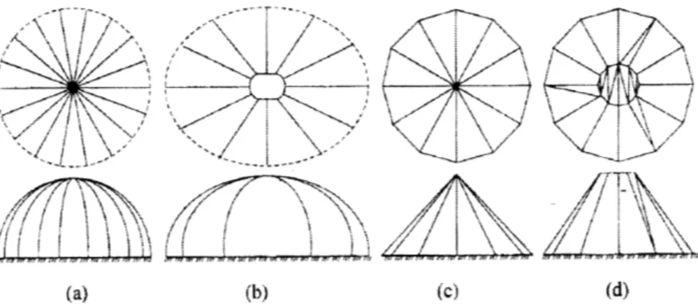
Braced rib dome consists of radially bracing ribs that are usually formed by various types of trusses such as the Pratt or Warren (Narayanan, 2006). There are many variations on these ribs depending on whether the stresses are high. Figure 3 shows some typical sections used for the ribs of a braced rib dome. Larger depths can be used for the trusses or additional bracing
elements such as struts and ties may be added for high stress areas (Narayanan, 2006).
Hfdiametical span
Figure 3: Typical Braced Dome Sections (Narayanan, 2006)
This type of ribbed dome generally requires the incorporation of a tension ring at the base to account for the thrust reactions at the bottom. These tension rings are typically made of
prestressed concrete, reinforced concrete or steel sections. When the ribs are pin connected to the foundation, then the dome is regarded as unstiffened (Narayanan, 2006). When the ribs are connected to the tension ring of the dome, then it is regarded as stiffened. In this latter case, the reaction from the ribs to the ground consists only of vertical forces. The horizontal reaction in the dome is taken entirely by the tension ring. The geometry of some typical braced rib domes
can be seen in Figure 4. The disadvantage for this dome system is that there may be too many rib members connecting at the crown. Therefore, a compression near the crown may be needed for the ribs to connect to, while only a few of the major ribs connect at the top of the crown. An
example of the braced rib dome is the Bell's Sports Centre in Perth. It is the largest laminated timber dome in the UK and has a diameter of 67 m, and covers a total area of 2973 sq. m.
(Narayanan, 2006).
(a) (b) (c) (d)
Figure 4: Typical Braced Rib Dome Configurations (Narayanan, 2006)
3.1.2 SOLID RIB DOME
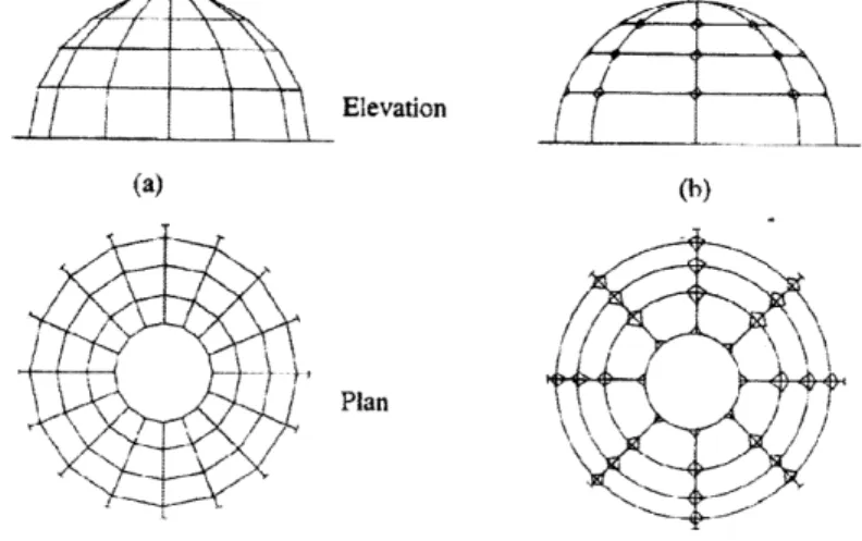
Solid rib domes consist of an arrangement similar to the braced rib dome. However, the
difference is that the ribs running along the longitudinal directional are not truss members but are instead shallower solid, rolled, built-up or boxed sections (Narayanan, 2006). Usually, there are
intermediate rings circling the dome in between the crown compression ring and the base tension ring as shown in Figure 5. For the solid rib dome, most types have all of the ribs terminating at the compression ring at the top rather than the crown (Narayanan, 2006). The appearance from below presented by this type of configuration is generally regarded as more aesthetically
pleasing. Therefore, no architectural or secondary cover may be required which results in cost in savings for material and labor (Narayanan, 2006).
Compression ring Icerdiate ring
Rib Elevation Tension ring
Plan
Figure 5: Typical Solid Rib Dome (Narayanan, 2006)
3.2
SCHWEDLER
DOMES
The Schwedler Dome is named after the German engineer J.W. Schwedler who introduced the structural system in 1863 when the first of its kind was constructed over a gas tank in Berlin (Narayanan, 2006). Schwedler also erected many other similar domes over his lifetime, the largest being in Vienna, in 1874 with a maximum span of 63 m (Narayanan, 2006). The
Schwedler dome is essentially a form of the braced ribbed dome. It consists of straight or curved ribs lying on a surface of revolution connected by polygonal rings which divide sections into different bays (Narayanan, 2006).
(a) (N (c)
(d)
Each of these bays may contain 1 or 2 diagonals that serve as bracing elements. Some typical geometrical configurations are illustrated in Figure 6. The benefit of the Schwedler is that it may be simplified to allow for easier analysis. The Schwedler dome becomes statically determinate if several simplifications are made. First, the connections are assumed to be pin connected. The second assumption pertains to the diagonals (Narayanan, 2006). Without diagonals, the structure is unstable. However, the lengths of these diagonals are usually very long and susceptible to buckling under compression. Therefore, when there are 2 diagonals in each bay, it can be
assumed that one is under tension and the other under compression. The compression member is assumed to fail under buckling. Therefore, for analysis, only 1 diagonal (under tension) is left for each bay (Narayanan, 2006). These two assumptions allow the Schwedler to be analyzed much more easily since it is now statically determinate. The largest Schwedler dome built spans over the Civic Centre at Charlotte, North Carolina. Built in 1955, it has a 100 m. diameter and a maximum height of 18 m. (Narayanan, 2006).
3.3
STIFF-JOINTED FRAMED DOMES
Stiff-jointed framed domes are similar to the Schwedler dome in all respects except that the ribs are continuous members and all the connections are rigid (Narayanan, 2006). The geometry and layout of the dome itself is the same as the Schwedler as can be seen from Figure 7. Therefore, it is also known as the rigidly jointed Schwedler dome. In other terms, it is also called the three dimensional form of the vierendeel truss (Narayanan, 2006).
(a) (b)
Plan
There are several main differences between the stiff-jointed framed dome and the Schwedler dome. First, the members of the Schwedler dome carries the external load via axial stresses while for the stiff jointed framed dome, axial forces as well as bending and torsional moments are present (Narayanan, 2006). Secondly, the Schwedler dome requires diagonal members in order to be stable. Otherwise, it forms a mechanism for instability (Narayanan, 2006). The stiff-jointed framed dome however is highly redundant and do not need diagonals to be stable (Narayanan, 2006). The third major difference is that while the Schwedler dome may be analyzed relatively easily by hand, complex matrix algebra and computer solutions are required for the consideration of the stiff-jointed framed dome (Narayanan, 2006).
3.4
PLATE TYPE DOMES
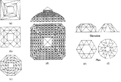
Plate type domes are basically the equivalent of the Schwedler domes except that it may be used to cover a rectangular area or any layout (Narayanan, 2006). The layout of some types of plate domes in rectangular and other polygonal shapes are demonstrated in Figure 8. There are higher numbers of small sizes with side planes filled by bars in the same plane which creates a
triangular network bracing system (Narayanan, 2006).
(b) 8
(d) (e) f)
(c)
3.5
NETWORK DOMES
The network dome is another variation off of the Schwedler type. The geometry is formed by
rotating each bay of a particular Schwedler dome by an angle of - with respect to the
n
latitudinally running ring below, where n is equal to the number of sides (Narayanan, 2006). As evident in Figure 9, this transformation creates 2 triangles lying in different planes.
Elevation
Plan
Figure 9: Network Dome (Narayanan, 2006)
This way, all of the members of the dome become stressed due to a point load exerted on any arbitrary location on the surface of the dome (Narayanan, 2006). Thus, this system is a more effective use of the structure. Although the network dome is theoretically more efficient than the Schwedler dome, it is difficult to construct (Narayanan, 2006). An interesting note of the
network dome is that it is only stable with an odd number of pin jointed connections (Narayanan, 2006). Currently, there are several companies that sell prefabricated domes of this type such as triodetic tubular domes and MERO from Germany (Narayanan, 2006).
3.6 ZIMMERMAN DOMES
This type of braced dome is named after Zimmerman who first built one of this type over the German Parliament (Narayanan, 2006). It is unique because it provided an effective method to
support the large horizontal thrust reactions of shallow domes (Narayanan, 2006). The structure
can be treated as statically determinate if the joints are considered to be pins. In addition, half of the supports should be modeled as ball bearings which are free to move in the horizontal
direction and providing only vertical reactions. The other half of the supports are modeled as pin supports, being restrained in the horizontal direction (Narayanan, 2006). Ball bearing supports are placed at the corners while the midpoints of the bars consisting of the tension ring are fixed to wall supports so that the horizontal thrust is counteracted by the wall along its stronger longitudinal axis. This removes the reactions against the wall at a perpendicular direction to the wall. Therefore, this allows support even by fairly slim walls (Narayanan, 2006). Some examples of Zimmerman dome configurations are demonstrated in Figure 10.
Elevation (a) Plan / --(b) (c) Plan (d) (e) '
Figure 10: Zimmerman Dome (Narayanan, 2006)
3.7 LAMELLA DOMES
The lamella system was invented in 1906 in Europe by Zollinger, a city architect from Dessau, Germany (Narayanan, 2006). The lamella dome was very popular in Germany before World War II and spread in usage to countries such as Sweden, Norway, Holland, and Switzerland
(Narayanan, 2006). The structural system was brought to the United States in 1925 by G.R. Kiewitt who constructed hundreds of these lamella systems in both timber and steel. It became
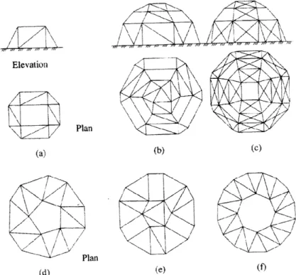
popular in the U.S because it is a good structural system in resisting wind, fire and seismic effects (Narayanan, 2006). The lamella system is formed from a number of similar types of units called lamellas arranged in a diamond or rhombus pattern. These lamella units can be clearly seen from the six sample configurations displayed in Figure 11. The advantage of the lamella system is that there is less crowding of rib members at the top of the dome (Narayanan, 2006). The geometry of the lamella dome is such that the panel loads at the rib intersection points are all almost equal in magnitude. The lamella units only need light struts. In addition, there is almost uniform stress distribution throughout the dome (Narayanan, 2006).
(a) (b) (C)
(d) (e) (t
Figure 11: Lamella Dome Geometries (Narayanan, 2006)
3.7.1 CURVILINEAR LAMELLA
The construction materials for curvilinear lamella domes may be steel, aluminum, or laminated wood (Narayanan, 2006). The members themselves may be either straight or curved. If the connections are all welded, then it is essentially a rigid frame and there is no need to balance thrust reactions at the base of the dome. However, if it is pin connected as for laminated wood
members, then a tension ring is required (Narayanan, 2006). The curvilinear lamella dome consists of using compression ring at the crown with intermediate rings. Ribs run from the bottom tension ring and end at the top compression ring. This system allows for higher
interlocking stiffness. It also provides for similar lengths for diagonal members between any 2 latitudinal rings as well as the same type of connections (Narayanan, 2006).
3.7.2 PARALLEL LAMELLA
The parallel lamella dome consists of division into many symmetrical sectors (lamellas) each of which are braced by 2 diagonal struts (Narayanan, 2006). Each of these diagonals is parallel to a major radial rib. It is also known as the Kiewitt dome (Narayanan, 2006). An example of the parallel lamella geometry is schematic (f) in Figure 11. Timber lamella domes are usually bolted with bolts and plate. Some notable parallel lamella domes include the Houston Astrodome and the Louisiana Superdome. The Houston Astrodome is one of the biggest steel frame domes in the world, spanning about 200 m with a maximum height of 63 m (Narayanan, 2006). The Louisiana
Superdome, located in New Orleans has a diameter of 207 m and a maximum height of 83 m. It
covers a total area of 5700 cu. m (Narayanan, 2006).
3.8
GEODESIC DOMES
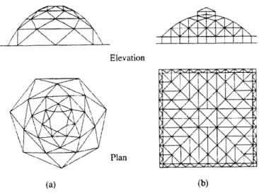
The geodesic dome is the more developed form of the lamella class of domes (Narayanan, 2006). Its use has become widespread mainly due to the influence of R. Buckminister Fuller
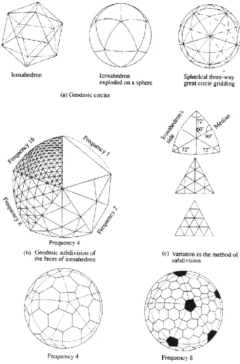
(Narayanan, 2006). Many advances and features of the geodesic dome were patented by either him or his company, Synergetics Inc (Narayanan, 2006). The traditional geodesic dome is formed by the creation of grids on the surface of spherical icosahedrons (Narayanan, 2006). Other types of shapes of polyhedra have now been also applied. The geometry intricacies of the geodesic dome are shown in Figure 12. There are several advantages for utilizing the geodesic geometry. It allows easy prefabrication since the lengths of the different members do not vary by much, even for domes of relatively long spans and for different bracing systems. Therefore, it has the benefit of being easily mass produced. In addition, the grid layout is very regular and
there is generally uniform stress distribution when loaded. The components or members of a geodesic dome is usually light and thus, easy to handle and transport. All of these factors contribute to its ease in erection when compared to other structural dome types. The geodesic dome in general is strong and stiff and can be adapted to very large sizes (Narayanan, 2006). The disadvantages of the geodesic dome include its irregular base and layout of its perimeter units. There may be architectural problems if certain shapes are used. Structurally, the geodesic dome is highly indeterminate and computer analysis methods are required (Narayanan, 2006).
lcosahedron Icosahedron exploded on a sphere
(a) Geodesic circles
Frequency 4 (h) Geodesic subdivision of
the faces of icosahedron
-Frequency
4--'\
Spherical three-way great circle gridding
(c) Variation in the method of
subdivision
FrequetKCy 8
4
TIMBER
Timber design and construction has traditionally been conducted based on experience of artisans and crafters. Only in recent times has design procedures been established based on engineering principles akin to steel and concrete design. The advent of such design procedures has allowed more efficient structural designs and construction. As a result, less material is required for a
similar structure as compared to when construction was conducted purely based on empirical means. Generally, more economical designs can be accomplished.
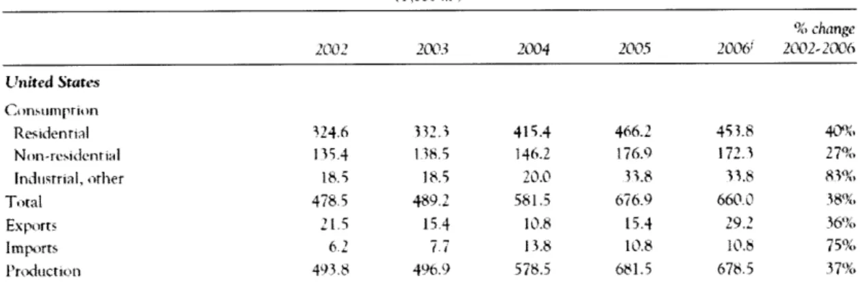
The contemporary structural materials used for construction are typically steel, reinforced concrete, and wood. In comparison by weight, more wood is used in construction than either steel or cement in the world (Stalnaker, 1997). Table 1 shows the consumption and production of glued laminated timber (glulams) in North America from 2002 to 2006.
Glulam consumptivn and prtxuction in North Anric, 2002-2006
% change 2002 203 2004 2005 2006 2002- 2006 United States Constimption Residenrial 324.6 332. 415.4 466.2 453.8 40% Non-residcntial 115.4 138.5 146.2 176.9 172.3 27% Indiustrial, other 18.5 18.5 20.0 33.8 33.8 8 3% Total 478.5 489.2 581.5 676.9 660.0 38% Exports 21.5 15.4 10.8 15.4 29.2 36% Imports 6 2 77 13.8 10.8 10.8 75% Production 493.8 496.9 578.5 681.5 676.5 37%
Table 1: Glulam Consumption and Production in North America, 2002-2006 (Forest Products Annual Market Review, 2005-2006)
As can be seen, there has been a substantial increase in the consumption of glulams in all sectors as well as in imports and production. This indicates the rising trend for the use of timber as
structural materials. Figure 13 shows the breakdown of material used for newly raised floors in North America. It can be seen that the use of wooden members in the form of I-beams, open wood web, and sawn wood dominate the market. This indicates the wide prevalence of the use of timber in construction applications.
New residential raised floors in North America, 2005
42%, 44%
13% 1%
N i-beam 44% OSteel 1%
IOpen w('xwl web 13% lMSawnwood 42%
Note: Types of Ixarns suppxorttrig raised floors (as opp sed to,
concrete slabs).
Source: APA - The Engineered WoVeV Assciation, 2006.
Figure 13: Composition of New Residential Raised Floors in North America in 2005 (Forest Products Annual Market Review 2005-2006)
The use of timber as a construction material does not need to be only restricted to residential
types of construction. With proper design and care of timber members, it has great potential in use for large scale projects, such as for dome applications as proposed in this paper.
4.1
STRUCTURAL TIMBER
Proper design of timber requires an intimate knowledge of its relevant properties.
4.1.1 DISADVANTAGES OF WOOD
There are several main disadvantages to the use of wood as a construction material which is primarily due to the organic nature of timber.
1) Variability of wood - there are no clearly reliable engineering data for wood due to the many differences between wood species, within species, from tree to tree, and even between different parts of the same tree. Timbers from different locales generate lumber
of extremely variable nature. There are increasing attempts to obtain more uniform wood sections by developing methods for faster growing and straighter growing trees than naturally grown types (Stalnaker, 1997).
2) Dimensional Instability - wood is easily affected by variables such as the change of moisture content and which can result in shrinking, swelling, and warping (Stalnaker, 1997).
3) Duration of loading - as wood is loaded for increased time periods, the strength of a wooden member decreases due to problems such as creep effects (Stalnaker, 1997). 4) Durability - timber is generally susceptible to environmental effects such as weathering,
decay, insect attacks and fire (Stalnaker, 1997).
Although there are many unfavorable characteristics attributed to timber, most or all of these can be controlled if the wood sections used are properly selected and treated to account for the environmental and loading conditions.
4.1.2 ADVANTAGES OF WOOD
There are many key benefits to the usage of timber as a structural material.
1) Economy- in comparison with structures constructed out of steel or reinforced concrete, wood construction is often cheaper to construct, especially for applications such as low-rise buildings (Stalnaker, 1997).
2) Aesthetics - wooden structures provide buildings with a more organic-looking
appearance as compared to the cold countenance of steel and concrete. (Stalnaker, 1997). 3) Ease of Working/Reworking - compared to steel and concrete, wood is much more easily
cut, shaped and connected on site. Prefabrication needs do not control the design of wooden members as it does for steel sections. For existing wooden structures, it is extremely easy to add additional components or make repairs (Stalnaker, 1997).
4) Durability - if proper consideration is used at the initial design stages, then wood can be a long-lasting structural material. As long as the proper timber species and grade is selected, wood may be extremely durable. It is important to avoid environmental conditions detrimental to wood, to use correct design details and necessary treatment required. (Stalnaker, 1997).
5) High Strength to Weight Ratio - this is especially true for structures that are constructed out of a single uniform material. A comparable building constructed out of timber is much lighter than one made of reinforced concrete. This characteristic is especially important for structures with large dead loading attributed to it (Stalnaker, 1997).
6) Beneficial thermal insulating properties - wood has a low thermal conductivity compared to other structural materials. The large number of voids in the structure of wood help to reduce the rate of heat transfer (Timber Construction Manual). Therefore, it is well-suited
for preventing heat loss and serves as a good natural insulator. As a result, less additional insulation is generally required, leading to economic savings (Stalnaker, 1997).
4.2
PROPERTIES OF
WOOD
Timber is divided into two main families of either hardwood or softwood. Their classification into either category depends on what type of species the tree belongs to. The names of hardwood
and softwood are misleading because it does not necessarily indicate that one is particularly harder or softer. Hardwood trees are angiosperms, with most having the properties of broad leaves and are often deciduous. Softwoods are mostly gymnosperms and have needle-like leaves,
Wood is an orthotropic material. The physical and mechanical properties of wood differ in all three dimensions, radially, longitudinally, and tangentially (Stalnaker, 1997). These different
axes are illustrated in Figure 14 .Some examples of the properties that vary along 3 dimensions include the strength, the modulus of elasticity, and the ratio of shrinkage and swelling. There are
six different Poisson's ratios for the various directions of wood (Stalnaker, 1997).
RADIAL AXIS
ANNUAL RINGS
(RAI AL
LONGITUDINAL
AXIS TANGENTIAL AXIS
Figure 14: Wood Axes and Reference Planes (Stalnaker, 1997)
Wood is made up of many wood cells. These cells are essentially hollow tubes that run along the direction of the grain (Stalnaker, 1997). Typically, hollow tubes are effective in resisting
compressive loads, which explains why wood has high resistance to longitudinal compression loading along the direction of the grain of the wood. The compressive strength of wood in the direction perpendicular to the grain is significantly weaker. This is because the hollow tube wood
cells have no compressive resistance in that direction. Their thin walls are easily flattened when a load is applied perpendicular to its long direction. The longitudinal tensile strength may be stronger than its longitudinal compressive strength if there are no defects. This is true for many materials since under tension, there is no need to worry about effects such as buckling in
compression. The longitudinal shear strength and transverse tensile strength is much weaker than the typical compressive and tensile strengths (Stalnaker, 1997).
4.3
FACTORS AFFECTING STRENGTH AND STIFFNESS
The major factors that affect the strength and stiffness of wood include moisture content, specific gravity, duration of loading, species, wood member size and shape, and the presence of defects (Stalnaker, 1997).
4.3.1 MOISTURE CONTENT
The moisture content of a wood sample is determined by the following equation:
(orig.weight - dryweight)
MC = 100 (orig.wegh - The strength properties of wood decreases as the
dryweight
moisture content increases until the point of moisture percent equals the fiber saturation point (Stalnaker, 1997). The reason behind the weakness of moist wood is that water is adsorbed onto the surface of the cell wall which weakens it (Stalnaker, 1997). The moisture content of wood changes depending on the local atmosphere in which it is located. The wood's moisture
content adjusts until it reaches equilibrium with the local temperature and relative humidity (Stalnaker, 1997). Wood shrinks as it loses moisture and swells as it gains moisture. The orthotropic nature of wood causes the rate of swelling and shrinking to be different along the 3 dimensions which results in warping of the wood (Stalnaker, 1997).
4.3.2 SPECIFIC GRAVITY
Both the strength and stiffness of wood depends on the amount of cellulose material that it possesses (Stalnaker, 1997). The specific gravity is a good measure of this property. Heavier woods, which usually has a higher specific gravity is stronger and stiffer than lighter woods (Stalnaker, 1997).
4.3.3 DURATION OF LOADING
The structural properties of wood are dependent on the load duration.
1) Creep - creep deflection occurs after loading has been sustained for a long time after immediate deflection (Stalnaker, 1997). The general creep deflection is shown schematically in Figure 15 which occurs after point A, the initial deflection. *D B C .o z 0 -J U-o A INITIAL DEFLECTION SA--TIME
Figure 15: Creep in Deflection of Wood Beam (Stalnaker, 1997)
Primary creep is an increase in deflection after load has been applied beyond immediate deflection (Stalnaker, 1997). Secondary creep is the horizontal part of the curve, in which no further deflection occurs for a while (Stalnaker, 1997).
Tertiary creep is characteristic of a much steeper increase in rate of deflection which leads to failure (Stalnaker, 1997). Tertiary creep usually only occurs for members under extremely high stress, which is not observed in most structures' lifetime. Depending on the intensity of loading, a structure may never reach tertiary creep or experience failure due to creep during the expected lifespan of the structure (Stalnaker, 1997).
2) Load duration factor- a factor introduced in the design of wood members in order to account for the effect that a sustained loading has on a wooden member
(Stalnaker, 1997). Figure 16 illustrates the influence of the duration of loading on the strength of wooden members.
IM PACT-PERMANENT --WIND 7 DAYS SNOW1 o wU a: >- I a U) Z r- < - < a: O 0 z Uj SI 0 > uJ DURATION OF LOAD
Figure 16: Effect of Load Duration on Strength of Timber Members (Stalnaker, 1997)
4.3.4 DEFECTS
Types of significant defects include the following:
1) Knots cause tensile stress components normal to the grain of knot, which is
especially bad for wood since the tensile strength normal to the grain is low (Stalnaker, 1997). The presence of knots reduces tensile, compressive and bending strength of wood members as illustrated in Figure 17.
STRENGTH NORMAL LOAD DURATION STRENGTH 1.9 1.8 1.7 1.6 1.5 1.4 1.3 1.2 1.1 1.0 nQI
AWAY FROM KNOT, AVERAGE TENSILE STRESS P/A (A PRINCIPAL STRESS)
AT KNOT, TENSILE STRESS PERPENDICULAR TO GRAIN
(IN COMBINATION WITH SHEARING STRESSES AND TENSILE STRESS PARALLEL TO GRAIN)
Figure 17: Effect of Knot on Stresses (Stalnaker, 1997)
2) Cross-grains occur when the direction of grain is not parallel to the edge of a piece of wood (Stalnaker, 1997). Almost all wood members have cross-grain present to a certain degree. The effect of cross-grain on beams and columns are shown in Figure 18. fb - Melt CROSS GRAIN BENDING FAILURE 2a MOHR'S CIRCLE (a) BENDING
-V
(h) COMPRESSION3) Checks and shakes are cracks in the wood in any one of the planes. Figure 19 and Figure 20 show some typical types of checks and shakes. These defects mainly reduce the longitudinal shear strength of wood (Stalnaker, 1997).
SURFACE THROUGH CHECKS
CHECK
Figure 19: Types of Checks (Stalnaker, 1997)
/
SURFACE THROUGH RING PITH
SHAKE SHAKE SHAKE SHAKE
Figure 20: Types of Shakes (Stalnaker, 1997)
4) Compression wood or otherwise known as "reaction wood" results from the
unsymmetrical growth of trees due to the long term bending stresses in a living tree (Stalnaker, 1997). For example, a tree that does not grow straight is subjected to eccentric dead loading. Large bending moments are induced on the tree as a result. At the compression side, thicker rings will grow in order to compensate for the higher stresses (Stalnaker, 1997). The wood also grows thicker and the
specific gravity results in being higher. However, this is not necessarily beneficial since the longitudinal shrinkage and swelling may be significantly higher than typical wood (Stalnaker, 1997).
5) Wane refers to missing wood in certain locations (Stalnaker, 1997).
4.3.5 TEMPERATURE EFFECTS
The change in temperature for wood results in effects on the dimension stability and the strength of wood. Higher temperatures cause wood to expand, at a different rate in each direction due to the orthotropic nature of wood. In addition, exposure to high temperatures (i.e. >150'F ) for long periods of time weakens wood. In between the temperature range of
11
0 to 1500F, the strength of 70 F dry wood changes by - % per degree (Stalnaker, 3 2
1997). Wood is stronger at lower temperatures and weaker at higher temperatures
(Stalnaker, 1997). If the exposure to higher or lower temperature is only for a short time, the strength of the wood returns to a normal level (Stalnaker, 1997).
4.4 DURABILITY OF WOOD
The general conception of wood as a construction material is that it is not as long-lasting or permanent as other types of materials such as steel or concrete. While wooden structures may be indeed susceptible to certain environmental factors, proper design and construction can reduce or eliminate most of these concerns.
4.4.1 DECAY, MOLDS, AND STAINS
The decay of wood occurs due to the attack of fungi originating from microscopic spores. Wood serves as a viable source of food for fungi. Fungi need several essential factors in order to survive. These are nutrients, air, moisture, and acceptable temperatures (Timber Construction Material). The lack of suitable conditions for any of these will prevent decay from fungi. The parameters that can be typically controlled out of the four are moisture and temperature. Wood will not decay if it is submerged in water and thus no air available, if the moisture content is kept below approximately 20%, or if the temperature is maintained below freezing or above 1000 F (Timber Construction Material). If these factors cannot be controlled, then wooden structural members must be treated with preservatives which make the wood poisonous to fungi. Another option is to select wood that is naturally resistant to decay (Timber Construction Material).
Molds and stains occur mostly to sapwoods. Molds are generally surface discolorings or
blemishes that can be cleaned (Timber Construction Manual). Fungal stains are more serious, in that it can physically enter into the wood and may not be easily removed by sanding or scraping
(Timber Construction Manual). Neither molds nor stains affect the strength or load bearing capacity of timber to any significant degree. It is mostly an aesthetic issue. The most serious effects are on shock resistance and toughness, and the tendency to hide decay under its disfigured appearance (Timber Construction Manual).
4.4.2 INSECT ATTACKS
On land, the insects with the most potential of damage to timber structures are termites. The more damaging type is subterranean termites that live in nests located in the ground. In the United States, the subterranean types of termites are mostly limited to the south (Timber Construction Manual). Subterranean termites enter buildings after they have been constructed. Subterranean termites require a source of moisture, such as from soil (Timber Construction Manual). By consuming wood, they can cause substantial damage to structural members leading to failure or instability. The best way to prevent subterranean termite damage is to make the structure inaccessible to them (Timber Construction Manual).
Non-subterranean or dry-wood termites have an impact along a narrow strip of territory from approximately central California to Virginia (Timber Construction Manual). The number of non-subterranean termites is generally fewer in number and therefore poses less of a threat on
wooden structures (Timber Construction Manual). However, negligent care towards buildings exposed to these termites can also lead to major damages. Chemical treatment of the wooden members is required to prevent attacks. Other types of insects that may cause damage to timber include wood-boring beetles, wood wasps, and carpenter ants (Timber Construction Manual). In each case, specialized procedures for prevention and cure are required.
4.4.3 CHEMICAL RESISTANCE
Timber generally has a higher resistance to chemical environments than other types of structural materials. Therefore, it is used in many applications for chemical storage and any chemical exposure (Timber Construction Manual).
4.4.4 FIRE CONCERNS
Even though timber is a combustible material, it can be designed so that it remains structurally sound in order to prevent immediate or sudden collapses. Protection of wooden members for fire includes application of fire-rated gypsum. Wood naturally develops a layer of protective char once it is subjected to flames (Timber Construction Manual). Even if the top layer of a wooden member chars, the wood underneath which is undisturbed still possesses strength and is able to bear loads. Its remaining strength capacity depends on how much of the wooden member is untouched by fire (Timber Construction Manual). The degree of structural strength left in the member depends on the size of the member and the rate at which that particular type of timber
chars. A benefit of utilizing wood under fire exposure is that while timber distorts due to radical temperature changes, it doesn't distort as much as other construction materials such as steel.
Therefore, there is less of a risk of inducing stress on adjacent structural members due to high temperatures (Timber Construction Manual).
All of the above factors must be considered when designing for timber structures. Many are unique to timber. Therefore, a designing engineer must be familiar with all of the properties that will affect the strength and durability of wood.
5
MODEL DEFINITION
The goal of this thesis is to analyze and evaluate the designs of a dome with a particular set of geometry and dimensions using different structural materials. The two different structural materials that will be compared are wood and steel. The structural behavior of the two differing schemes will be considered, as well as other factors such as economics, feasibility, and overall efficiency.
Timber is a traditionally-utilized construction material that has recently received revitalized interest due to environmental concerns. Although timber is still a widely used structural material, domes are not often constructed out of wood. Steel, however is widely used for braced dome
schemes due to its high strength in compression and tension, as well as its relatively low weight for its high strength. The goal of this study is to compare the advantages and disadvantages of both models and to propose the more efficient scheme based on factors such as material weight,
cost, and sustainability.
5.1
MODEL TYPE AND GEOMETRY
The braced dome scheme selected for consideration in this thesis is that of a skeleton single layer dome. The reason for this choice was primarily driven by the fact that this is the most common type of braced dome being constructed. More specifically, the dome will be of the lamella type.
Figure 21: View of Model Geometry
The lamella system allows duplicate member lengths and connections for each section between the latitudinal rings. The lamella dome also has high inherent stiffness characteristics. These are the reasons why the lamella system was chosen for this study.
The model used for the analysis has a diameter of 300 ft. and a maximum height of 100 ft. These dimensions provide a rise-to-span ratio of 0.33, which is comparative with many other wooden domes in existence. These dimensions were chosen after considering the typical size of dome structures. The purpose of the study is to determine the more efficient structural material between wood and steel for a reasonably sized dome. The diameter of 300 ft. is approximately the average size of large scale domes for intentions of sporting events and exhibition halls. The height was then obtained by also using an average rise-to-span ratio of 0.33. This ratio is a reasonable number because it produces a geometry that is not too shallow, which would cause high horizontal thrust at the base of the dome. At the same time, it is not too high which would detract from the visual aesthetics of the geometry. In addition, a larger height value would also cause inefficiency in material. Figure 22 illustrates the main relevant dimensions for the dome structure, such as the diameter and various heights for intermediate rings. The plan view of the lamella dome is displayed in Figure 23.
5,-3.
Figure 22: Side View of Dome Model with Typical Dimensions
The members between intermediate concentric rings all have identical lengths, which is an advantage for the lamella dome since it results in easier production and assembly. The lengths of the diagonal members for each level of intermediate ring are shown in Figure 24.
6"
22'-8"
6'-8"
25'-10"
29'-10
Figure 24: Dome - Diagonal Dimensions
5.2
SAP2000 MODEL ANALYSIS
The geometry of the dome was defined in the program Rhinoceros 4.0. Although the dome is curved in appearance, all of the members were actually drawn as straight members. This is to allow easier facilitation of the fabrication and construction processes. It will also allow the members to be only under axial stress since the model also incorporates only pin connections. Moment will be induced in the members if they are curved, even if the connections are pin-connected. The model was then imported into the structural analysis program SAP2000 for further analysis.
Figure 25 shown below is a display of the axial stresses of the dome model when placed under the dead load due to the self-weight of the members themselves. The members in red are under
compression while the yellow members are in tension. As can be seen, the dome has a tendency to want to splay out and expand at the bottom. Therefore, a tension ring is required in order to keep the dome from expanding. At the crown of the dome, the diagonal members connect to a
compression ring.
Figure 25: Axial Stress Diagram of Dome Model Under Self-Weight
Since all of the members will be subjected to axial stresses, the steel and timber sections proposed for design will have circular cross-sections. For steel, HSS pipe sections will be utilized. For timber, round wooden logs will be used. The circular cross-section provides a very efficient geometry for compression loadings.
5.3 LOADINGS
The dominant loads considered for analysis includes: self-weight of the members, dead weight of cladding, roof live load, snow load, wind load, and seismic load. The structure was considered to be located in Boston, Massachusetts. Therefore, the snow load, wind load, and seismic load were designed based on the data given for that locale.
5.3.1 DEAD LOADS
The dead load for the dome structure is primarily the cladding and any types of MEP/HVAC equipment that will be hung under the roof cover. Evidently, the type of cladding used may be different depending on whether it is the steel or timber model. However, since it is desired to place the same type of loading on both models, a uniform load of 30 psf is assumed for the cladding and 15 psf for MEP/HVAC allowance. This results in a total dead loading of 45 psf.
5.3.2 LIVE LOADS
The uniform live loading for ordinary flat, pitched and curved roofs is given by ASCE 7-05 to be 20 psf.
5.3.3 SNOW LOAD
The snow loading was determined using ASCE 7-05. The values for the flat roof case were adjusted in order to account for the curved surface of the dome roof. Both the balanced and unbalanced case of snow loading was considered. The unbalanced case is simply the application of the snow load while accounting for wind effects which will cause snow drift off of the roof surface, resulting in unbalanced snow loading.
The pitch of the dome roof was determined at each location between intermediate rings. The values for these angles are shown in Figure 26.