HAL Id: inria-00550595
https://hal.inria.fr/inria-00550595
Submitted on 28 Dec 2010
HAL is a multi-disciplinary open access
archive for the deposit and dissemination of
sci-entific research documents, whether they are
pub-lished or not. The documents may come from
teaching and research institutions in France or
abroad, or from public or private research centers.
L’archive ouverte pluridisciplinaire HAL, est
destinée au dépôt et à la diffusion de documents
scientifiques de niveau recherche, publiés ou non,
émanant des établissements d’enseignement et de
recherche français ou étrangers, des laboratoires
publics ou privés.
The MaggLite Post-WIMP Toolkit: Draw It, Connect It
and Run It
Stéphane Huot, Cédric Dumas, Pierre Dragicevic, Gérard Hégron, Jean-Daniel
Fekete
To cite this version:
Stéphane Huot, Cédric Dumas, Pierre Dragicevic, Gérard Hégron, Jean-Daniel Fekete. The
Mag-gLite Post-WIMP Toolkit: Draw It, Connect It and Run It.
ACM Symposium on User
Inter-face Software and Technology (UIST 2004), 2004, Santa Fe, NM, United States.
pp.257-266,
�10.1145/1029632.1029677�. �inria-00550595�
The MaggLite Post-WIMP Toolkit:
Draw It, Connect It and Run It
Stéphane Huot, Cédric Dumas
Ecole des Mines de Nantes
4, rue Alfred Kastler
44307, Nantes, France
Tel: (+33) 251-858-241{shuot, cdumas}@emn.fr
Pierre Dragicevic
LIIHS-IRIT
118, route de Narbonne
31062, Toulouse, France
Tel: (+33) 561-556-965dragice@irit.fr
Jean-Daniel Fekete
INRIA Futurs/LRI Bât. 490
Université Paris-Sud
91405 ORSAY, France
Tel: (+33) 169-153-460 Jean-Daniel.Fekete@inria.frGérard Hégron
CERMA UMR CNRS 1563EAN, Rue Massenet
44319, Nantes, France
Tel: (+33) 240-594-324
hegron@cerma.archi.fr
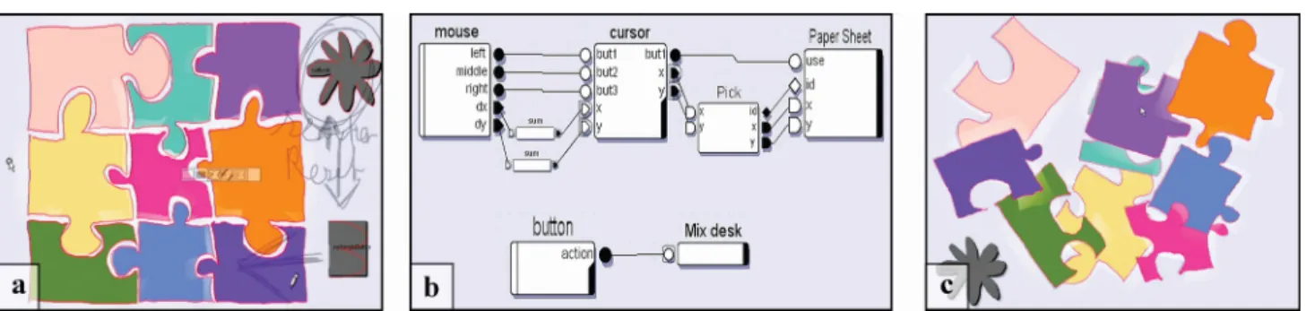
Figure 1: Designing a puzzle UI with MaggLite. (a) Drawing UI. (b) Configuring interactions. (c) Using the application.
ABSTRACT
This article presents MaggLite, a toolkit and sketch-based interface builder allowing fast and interactive design of post-WIMP user interfaces. MaggLite improves design of advanced UIs thanks to its novel mixed-graph architecture that dynamically combines scene-graphs with interaction-graphs. Scene-graphs provide mechanisms to describe and produce rich graphical effects, whereas interaction-graphs allow expressive and fine-grained description of advanced interaction techniques and behaviors such as multiple pointers management, toolglasses, bimanual interaction, gesture, and speech recognition. Both graphs can be built interactively by sketching the UI and specifying the interac-tion using a dataflow visual language. Communicainterac-tion between the two graphs is managed at runtime by compo-nents we call Interaction Access Points. While developers can extend the toolkit by refining built-in generic mecha-nisms, UI designers can quickly and interactively design, prototype and test advanced user interfaces by applying the MaggLite principle: “draw it, connect it and run it”.
Categories and Subject Descriptors: H5.2 [Information Interfaces]: User Interfaces―Graphical user interfaces
(GUI), User interface management systems (UIMS), Inter-action styles, Prototyping, Input devices and strategies; D2.11 [Software Engineering]: Software Architectures.
Additional Keywords and Phrases: GUI toolkits, GUI architectures, ICON, MaggLite, interaction techniques,
interaction design.
INTRODUCTION
Most GUI toolkits are based on heavyweight components that encapsulate presentation and interaction into single monolithic components. Using such architectures, extend-ing either the presentation or the interaction of components is challenging, sometimes even impossible. Without exten-sive built-in support for Post-WIMP interaction techniques and alternative input, developing advanced GUIs is a long and expensive process. Although prolific work has been carried out on new user interface toolkits, there is still a strong need for tools that would allow easy development or prototyping of advanced and innovative interactive applica-tions. The MaggLite Post-WIMP toolkit is a new step toward such tools. Relying on a multi-input interaction model and fine-grained scene-graph architecture, MaggLite offers new possibilities in designing user interfaces:
From the UI design perspective, MIB, a sketch-based interface builder included in MaggLite, allows very-high-fidelity prototyping of post-WIMP user interfaces. Interac-tions are specified graphically using the ICON data-flow
editor [10]. The tools and mechanisms provided by Mag-gLite (Interface Builder, base components, tools
abstrac-tions and generic interacabstrac-tions) offer a high flexibility that eases the work of the UI designer, whether he is a graphic designer or a programmer. While developers can easily extend the toolkit by refining generic mechanisms, UI de-signers can rapidly prototype and test advanced user inter-faces by applying the MaggLite principle: “draw it, connect it and run it”.
From the UI architecture perspective, the scene-graph architecture provides mechanisms to easily manage ad-vanced graphical effects (transformations, transparencies, shadows, fading, etc.) and the interaction-graph provides an efficient way to specify interactions and connect physi-cal input devices to the application components and tools. This fine-grained description of interaction improves flexi-bility and extensiflexi-bility of the toolkit compared to traditional event-based architectures. The MaggLite architecture uses a novel mixed-graphs model, where appearance and inter-actions are intertwined but still described separately. The dynamic combination of the graphs makes UIs fully recon-figurable at runtime.
From the toolkit perspective, MaggLite allows for high input-independence by introducing the concept of
plug-gable interaction techniques as bridges between physical
input devices and application objects. MaggLite also pro-vides built-in support for most non-standard input devices (tablets, joysticks, MIDI-devices, webcams, etc.) while remaining extensible. The whole toolkit is designed with interchangeability of input devices and interaction tech-niques in mind. As a result, many appearances and behav-iors can be composed, tested and refined in a very short time when designing advanced GUIs.
The next section introduces the main concepts behind Mag-gLite by walking through the design of a sample “puzzle” application. Then, we describe the MaggLite architecture and discuss related work before concluding.
UI DESIGN WITH MAGGLITE
MaggLite introduces a straightforward UI design process in three steps:
1. Draw it: Using the sketch-based interface builder (MIB for MaggLite Interface Builder), an UI designer draws components on the UI space. These graphical objects are usable immediately after they are created.
2. Connect it: With ICON, interactions are graphically described using a dataflow visual language that allows specifying and reusing advanced interaction techniques. Convincing mock-ups can be built without writing one line of code.
3. Run it: The designed UI is fully functional during crea-tion; it can be executed, refined and saved. The saved configuration can be reloaded 1) as a mock-up from a generic application, 2) from the specific application is has been created for, or 3) from another application for reusing parts of its behavior or graphical components.
To illustrate it, we will observe Geoff, a UI designer, creat-ing a sample “puzzle” application uscreat-ing MaggLite.
Designing a puzzle UI with MaggLite
As a designer, Geoff can create simple script-based pro-grams but prefers graphical interactive tools to express all his creativity when designing UIs. He is usually asked to create functional applications instead of mere bitmaps or screenshots, in order to test and evaluate the feasibility and usability of the UI. In our scenario, Geoff has to design the UI for a simple and intuitive puzzle game. We show how MaggLite built-in tools help him in carrying-out this task. Drawing the UI (Figure 1a). To design his puzzle UI graph-ics, Geoff successively uses the tools available on the MIB toolglass. Each time he draws a stroke starting from inside an area of the toolglass, an object of a specific type is cre-ated or a command is applied to the underlying object. 1. Freehand sketching tool: Geoff draws each piece of the
Puzzle by initiating a drawing through the “basic com-ponent” area of the toolglass (Figure 2). This tool is used to draw freeform UI components, and is well-adapted for our puzzle example. The shape of the cre-ated object is given by the entire stroke.
Figure 2: Sketching a component with MIB.
2. Color changing tool: Geoff changes the color of the puzzle pieces by moving the “colorizer” area of the toolglass over the object and clicking through it (Figure 3). The colorizer’s attributes (current foreground and background colors) can be changed beforehand.
Figure 3: MIB - Changing colors with the toolglass. 3. Gesture tool: after he has drawn the puzzle pieces,
Geoff adds a button that will trigger the shuffling of the pieces. By drawing the appropriate gesture, he creates a rectangular button (Figure 4). Each time a gesture is recognized, a predefined object is created or an action is performed (deletion, move, etc.). If gestures are not recognized, strokes are kept as annotations (Figure 4c). Finally, Geoff decides to design a fancier button. He draws a flower-shaped button (top right of figure 1a)
with the freehand sketching tool before erasing the rec-tangular one with a gesture.
Figure 4: MIB - Gestures. (a) start of a new ges-ture. (b) recognized (c) unrecognized (annotations).
Advanced post-WIMP interfaces often rely on non-rectangular shapes for their graphics. MaggLite supports freeform shapes with graphical effects such as transpar-ency. Furthermore, MIB has been developed with the MagLite toolkit itself and makes rich use of Post-WIMP techniques: in addition to toolglasses, it exploits freehand sketching and gesture recognition with stylus devices in order to make UI design simple and natural, close to de-signer habits (as with SILK [23,24]). If some dede-signer prefers other interaction techniques for building UIs, MIB can be applied to itself.
Configuring and Running the UI (Figure 1b). When Geoff adds new components, he can graphically specify how they are controlled with input devices using the ICON data-flow
editor. The basic building blocks of ICON are called “de-vices”, which denotes physical input devices but also filters (we come back to ICON in the next section). To describe
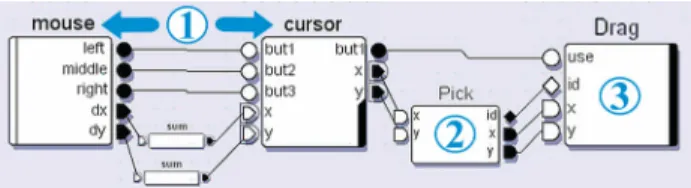
the behavior of his puzzle UI, Geoff starts by connecting the outputs of the “mouse” device to the inputs of a “cur-sor” feedback device (Figure 5, step 1). At this point, he is able to move a cursor over the UI graphical components with his mouse. Now, Geoff needs to describe the interac-tion with the graphical components.
Figure 5: Puzzle interaction configuration in 3 steps.
MaggLite provides specific devices to link interactions and UI components: Interaction Access Points devices (IAPs for short). For his puzzle, Geoff uses two kinds of IAPs:
interaction devices and manipulators.
Geoff adds a picking device in the dataflow diagram and connects it to the cursor (Figure 5, step 2). Picking is thus enabled: each time it receives a new cursor location, the picking device sends on its output slots the list of picked objects and the coordinates where the pick occurred. Geoff then decides to use a simple drag interaction to move the pieces so he connects the MaggLite drag device after the picking device. Because Geoff wants the dragging to start when the mouse button is pressed he connects the button
output slot of the cursor to the “use” slot of the drag device. He can now drag picked pieces (Figure 5, step 3).
Geoff soon realizes that a drag interaction is not well adapted, because he is only able to translate the pieces, not rotate them, so without leaving the application, he replaces the drag device with the “paper sheet” device (Figure 1b). The “paper sheet” technique, described in [5], allows trans-lating and rotating an object with a single gesture. Like other interaction techniques, it is available in MaggLite as a simple IAP device.
Now, Geoff needs to specify the behavior of the “shuffle” button. For this purpose, each MaggLite graphical compo-nent created using MIB also appear as a device in ICON.
Those devices are called manipulators. Geoff’s button manipulator has an “action” output which sends the Boo-lean “true” value each time the button is clicked (Figure 6).
Figure 6: Button manipulator.
During the initial design, the button is not connected to any action but later, Geoff asks a programmer to create a “Mix Desk” device to shuffle the puzzle pieces. Once the pro-grammer is done, Geoff plugs the output slot of the button manipulator to the input slot of the “Mix Desk” device (Figure 6). The shuffling function is the only part of this application that has to be programmed. Simpler actions can sometimes be built graphically using existing ICON devices
or programmed directly inside the editor with “scripting” devices that interpret JavaScript code.
Using, refining and shipping the designed UI (Figure 1c). Geoff has now made a fully functional puzzle UI he can save into an XML file that can be launched by any user having MaggLite installed. This final puzzle application is illustrated in Figure 1c. The original gestures and annota-tions are not displayed anymore, though saved in the file. At this stage, the interaction and the appearance are still fully configurable at runtime. Geoff himself can continue to refine the puzzle and test other interaction techniques. For example, he can replace the mouse by a tablet to move the pieces and use the pressure sensitive capabilities of the stylus to adjust the moving speed. He can also directly connect a keyboard key or a speech command to the “Mix Desk” device as a shortcut for shuffling the pieces. He can even duplicate his original dataflow diagram, allowing for multi-user interaction with the puzzle. All these configura-tions can be saved and proposed as alternatives to different users, depending on their personal taste, abilities or hard-ware configuration.
The puzzle application was actually built in about ten min-utes by one of the authors. This simple scenario aimed at showing how MaggLite and its associated tools can be used for building Post-WIMP interactive applications graphi-cally. In the next section we describe MaggLite’s architec-ture and mechanisms and give more examples of use.
MAGGLITE
MaggLite is a Java toolkit that relies on a mixed-graphs model to describe both appearance and behavior of interac-tive applications. A mixed-graph is made-out of a scene-graph, an interaction-graph and mechanisms to communi-cate between them. As previously seen, MaggLite also provides two interactive builders: MIB for interactively editing the scene graph and ICON to interactively specify the interactions and connect them to the scene-graph and the application-specific behaviors.
The mixed-graphs model
The MaggLite graphical part builds upon classical scene-graph approaches. This common model for 3D toolkits has already been used by some advanced 2D toolkits [7,3,25]. Scene-graph approaches break the heavy structure of wid-get-based architectures by using fine-grained graphical objects that can be grouped to create more complex graphi-cal objects. MaggLite goes beyond the scene-graph ap-proach by decomposing not only graphics, but also interac-tions. Interactions are described by interaction-graphs that break the input-event structure into dataflow graphs. Those graphs are made of interconnected filters we call “devices”, which can be in turn decomposed into individual channels. The interaction-graph dynamically updates the scene-graph structure and components when needed, i.e. in reaction to user input or system events. The mixed graphs architecture makes a clear distinction between the appearance and the behavior of the interface [22]. Furthermore, the interaction-graphs can be reconfigured graphically in many ways to adapt the UI or to test alternative interaction techniques at runtime.
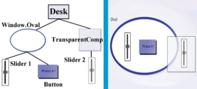
Figure 7: A simple MaggLite scene-graph and the corresponding interface.
Scene-graphs. A MaggLite scene-graph is made up of a
root object, the desk, and nodes that are graphical objects (Figure 7). The MaggLite toolkit provides several classes of graphical objects but most of them can be instantiated with arbitrary shapes. This shape abstraction allows more expressivity in designing the interface appearance as
ob-jects are not limited to rectangular or elliptic shapes. Graphical properties, such as colors, geometrical transfor-mations or opacity, are embedded into objects and propa-gated to child nodes by graphic contexts.
MaggLite provides a predefined set of atomic graphical
objects with several possible states (transparent, stuck,
layers, etc.). The toolkit also includes composite graphical
objects which encapsulate predefined scene-graphs having
a well-defined behavior. For example, the slider of Figure 8 combines a pane and a thumb and constrains the thumb location to the slider’s internal model. All regular widgets (buttons, sliders, windows, etc.) can be implemented as composite objects. Predefined atomic and composite ob-jects can be extended by inheritance whereas new ones can be created from abstract classes and interfaces.
Figure 8: A widget defined by a scene-graph of atomic graphical objects.
One major issue with most classical scene-graph ap-proaches is that interaction is described together with graphics by adding special nodes in the scene-graph, if not simply hiding it inside graphical nodes. To achieve more flexibility and extensibility, our mixed-graphs model de-scribes interactions separately in interaction-graphs. Inter-action-graphs rely on ICON [10], a toolkit we previously developed for handling advanced input. So that following sections about interaction-graphs could be understood, we give in the next section a brief overview of the ICON model
and graphical language.
The ICON (Input Configurator) Toolkit. ICON is a Java
toolkit and interactive editor for creating input-reconfigurable interactive applications, i.e. applications that can be controlled using a wide range of input devices and interaction techniques [10]. ICON introduces a reactive
dataflow architecture that describes input methods using interconnected modules.
ICON’s model is based on devices, which are a broad
gen-eralization of input devices: ICON’s devices can produce
output values, but can also receive input values. A device contains typed channels called input slots and output slots, as well as parameters to configure them. Slot types have a distinct graphical representation depending on their type (e.g. circle for Booleans, triangle for integers) and can be hierarchically grouped to form structured types (Figure 9). There are three main categories of devices: system devices describe system resources such as input peripherals (mice, keyboards, tablets, speech input, etc.); library devices are
system-independent utility devices that range from simple boolean operators to complex feedback/interaction devices such as cursors, toolglasses and gesture recognizers;
appli-cation devices are devices that control appliappli-cation (domain)
objects. System and library devices are part of the toolkit whereas application devices are meant to be implemented by application programmers through a straightforward process.
Figure 9: ICON components graphical representation. An output slot of a device can be linked to one or several compatible input slots of other devices by connections, which are represented by wires (Figure 9). A set of con-nected devices defines an Input Configuration that can be executed by ICON’s reactive interpreter. ICON’s graphical editor allows mapping input devices to applications interac-tively. Currently plugged input devices and all devices of the ICON library are shown on a container and just have to
be dragged towards the editor’s pane to be used. The map-ping task may involve insertion and connection of devices that encapsulate predefined interaction techniques (e.g., a gesture recognizer is meant to be inserted between a point-ing device and a text input component) as well as the de-scription of new interaction techniques by the combination of simpler processing devices.
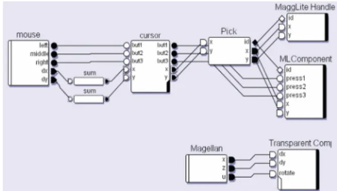
Figure 10: A possible interaction-graph (described by an ICON configuration) for the scene-graph of Figure 7.
Interaction-graphs. A MaggLite interaction-graph is an
ICON configuration describing the way a scene-graph can
be manipulated (Figure 10). The same way as scene-graphs
break heavy graphical structures into primitive graphical components, interaction-graphs break heavy event struc-tures into dataflow processing devices and slots. This data-flow paradigm allows the description of interactions at a finer grain than using standard input events. For example, in event-driven toolkits, there is an event type for each kind of input device. To support a new device type (such as a game pad or a pressure sensitive stylus), a new input event type has to be defined, the event dispatch mechanism has to be adapted for this new type of events and each object has to be extended to handle the new event. With MaggLite, if the new input device is not yet supported, one just needs to implement a new device for it. Once available, it can be used like any other existing device to control graphical objects through existing or new interaction techniques.
Interaction Access Points (IAPs)
As described in the puzzle example, IAP devices provide different ways of linking ICON devices (input devices) to MaggLite graphical components. In our mixed-graphs paradigm, IAPs are dynamic connection points between the interaction-graph and the scene-graph. Each time a new graphical object is created, it also appears as a device into ICON’s device pane. IAPs can be considered as “runtime glue” to dynamically compose a mixed-graph. They trans-mit and receive data from the scene-graph or modify its structure by inserting or removing nodes, changing their properties or triggering special behaviors. We distinguish three kinds of IAPs: interaction devices and manipulators (mentioned in the puzzle example), as well as InnerTools.
Interaction devices. We introduced interaction devices
with the Picking device in the puzzle example. We de-scribe it further and also dede-scribe a pluggable interaction technique called Responsive Handles.
The picking device communicates with the desk, root of the scene-graph. Each time it receives new positional values it asks the desk for nodes of the scene-graph under the given location. It then sends references of picked objects through its output slot. Due to this externalization of the picking operation, MaggLite is not limited to one picking tech-nique. Currently, MaggLite supports the conventional
under-cursor picking (with several strategies) and prox-imity-picking (all objects within a certain distance are
pick-ed, which can be materialized as a halo surrounding graphical objects).
Classical UI architectures encapsulate interactions within objects. In MaggLite, interaction techniques are pluggable. Graphical components declare their capabilities by imple-menting Java interfaces whereas each interaction device is specialized into a specific capability. For example, a graphical object willing to be moved needs to implement the “Moveable” interface, which makes him compatible with interaction devices such as “Drag” and “Paper Sheet”. This mechanism avoids heavy coding when implementing new interaction techniques and can be found in other ap-proaches such as instrumental interaction [4]. We will
illustrate this by adding a new manipulation technique called Responsive Handles.
Figure 11: Responsive Handle interaction technique provides a generic interaction with movable objects.
The Responsive Handles technique works as follows: when the pointer reaches the proximity of a moveable object, a handle appears right on its shape boundary. This handle follows the pointer as long as it stays in the object prox-imity. The user can drag the handle to move the object. Figure 11 illustrates this technique and Figure 12 shows the underlying communications in the mixed-graphs model. When a moveable object is proximity-picked a handle is inserted in the scene-graph just before the object. When it is moved, the handle moves the object accordingly. The moving of the handle itself is managed by a conventional drag device. When the object proximity is not picked any-more, the responsive handles device removes the handle from the scene-graph.
Figure 12: Mixed-graphs – Responsive Handle. Pick receives signals, and queries for picked objects (1). It transmits values to the handles device (2) which inserts a handle object in the scene-graph (3).
Other MaggLite pluggable interaction techniques include: • All advanced interaction techniques provided by ICON,
such as speech and gesture recognition, toolglasses, etc. • an event producer device, which integrates MaggLite to
Swing’s event-driven architecture,
• drag and “paper sheet” [5] interactions, that provide mov-ing moveable objects,
• the Magnifier, which zooms parts of scene-graphs, • the Fisheye, which apply a fisheye lens deformation on
parts of scene-graphs.
Manipulators. Unlike generic interaction devices which
can potentially manipulate any scene-graph object of a given class, manipulators deal with instances i.e. individual scene-graph nodes. As explained in the puzzle example, an object manipulator is an ICON device that externalizes entry and output points to interact with the object. For example, a moveable object externalizes move slots, which expect to receive coordinates. Figure 13 shows a moveable object connected to a joystick. This principle of direct association is a simple and efficient way for performing direct manipu-lation [4].
Figure 13: Direct connection between an input de-vice and a manipulator dede-vice.
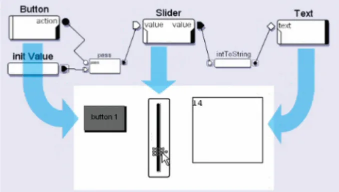
Manipulators can also be useful to describe interactions between UI components (Figure 14). The behavior of the three widgets is configured graphically as follows: the out-put value of the slider is connected to the inout-put of the text zone by a conversion device. When the slider is moved, the text zone displays the slider’s value. When the button is pressed, the “pass” device resets the slider’s value to the constant specified by the “intValue” device. Such interac-tion-graphs are well-adapted to explain UI mechanisms and prototype them in an educational context.
Figure 14: Connection of manipulators devices. The button resets the slider and the slider value is displayed in the text zone.
InnerTools. MaggLite provides a third way to manage
interactions that was not used in the puzzle example:
Inner-Tools. These tools are IAPs that receives positional values
(in screen pixel coordinates). When an InnerTool is added to a compatible object, it is active only within the bounds of the object. It also maintains a cursor if needed (Figure 15). A DrawInnerTool, implementing drawing actions, is in-cluded in MaggLite to allow easy creation of drawing
inter-faces. We use it as example to explain how InnerTools are processing coordinates, and therefore their two behaviors:
Figure 15: InnerTools – Full mapping mode.
1. Full mapping: received positional values are converted into component local coordinates. This mode is well-adapted to absolute pointing input devices (e.g. tablets) because the device is entirely mapped to the component. On Figure 15, the DrawInnerTool is connected to a digitiz-ing tablet device, in full mappdigitiz-ing mode.
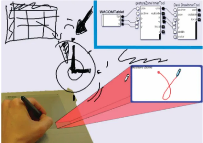
Figure 16: Using InnerTools in global mode to re-strict interactions to an input device zone.
2. Global mode: when an InnerTool is not used in full mapping mode, received positional values are interpreted in screen coordinates. The tool is active when the coordinates are inside the bounds of the linked component. In other cases, the tool is inactive and coordinates are sent through the InnerTool’s output slots. Figure 16 shows two Inner-Tools in global mode, connected together. The first one, named gestureZone, is linked with the blue bordered com-ponent and performs gesture recognition. Its input slots are connected to a tablet. The second tool is a DrawInnerTool linked with the application desk. Its input slots are con-nected to the forwarding output slots of the gesture tool. When the tablet send screen coordinates that are in the bounds of the gesture zone component, the linked gesture tool is activated and doesn’t forward any values to the desk
drawing tool. When coordinates are outside of the gesture zone, the gesture tool is disabled and it forwards coordi-nates to the desk drawing tool. Therefore, the user can draw anywhere on the desk, except in the gesture zone where his strokes are interpreted as gestures. This mapping of screen areas into input devices is an effective way to specify post-WIMP interactions, especially when working with tablets, screen tablets or touch-screen devices.
When an InnerTools is added in an interaction-graph, it installs its feedback (the cursor) in the scene-graph on top of the component the tool is linked with. This allows the feedback to be painted over the component. Then, when the “use” signal is triggered on the device, its action method is executed to perform the implemented interactions. Mag-gLite provides three working InnerTools: a drawing tool, an erasing tool and a generic tool used to restrict an existing interaction technique to the bounds of a component. Addi-tionally, developers can easily extend the InnerTools set by subclassing the InnerTools class. They only have to im-plement the “action” method as other mechanisms (input handling modes, feedback, coordinates conversions) are inherited.
Extending MaggLite
MIB was developed to ease the prototyping of advanced UIs with MaggLite. It is also a good example of an appli-cation developed with MaggLite and extending it. It took one of the authors about two hours to implement MIB. MIB has a main IAP named “MaggLiteBuilder”. It re-ceives a command and a shape, in fact the class and the shape of the object to insert in the application scene-graph. Therefore, it can be connected to any device able to send commands and/or shapes (voice commands, gesture com-mands, drawing tools, etc.) The MaggLiteBuilder device is also able to save created UI into an XML file.
In its default input configuration, the MIB main tool (sketch, gestures and color changing) is controlled with a tablet and the toolglass is moved with a Magellan (6DOF isometric device). A mouse can be used to move created objects. A MIDI fader box allows specifying the colors of the colors changer (one fader for each RGBA component). Like all MaggLite applications, MIB can be controlled with other types of input devices and interaction techniques embedded in the toolkit (voice recognition for changing colors, mouse for sketching, keyboard for selecting object classes, etc.)
A more complex application and toolkit extension is cur-rently under development: Svalabard [19], a sketch-based 3D modeler. User studies conducted in the early stages of this work as well as the state of the art show that post-WIMP techniques are essential to bring creativity in 3D modeling. This project heavily uses and extends MaggLite by adding domain-specific components and devices such as drawing filters or user behavior analyzers. Those new devices and components are added to the toolkit. Once added however, they can be easily reused in other
applica-tions. Finally, we describe a scatter plot visualization built with MaggLite as an example of use of the toolkit applica-tion template.
Building a Scatter Plot Visualization using MaggLite
MaggLite is not a visualization-dedicated toolkit but allows rapid development of advanced visualization techniques. “MaggLiteVisu” is an application that allows displaying 6-dimension data using scatter plots [13]. An example data-set can be census data with attributes such as city names, population, area, crime, etc. Each entry of the dataset, loaded from an XML file, is visualized with a rectangular graphical object. Attributes of the dataset are then assigned to graphical properties of the component (width, height, color, position). It took us only ten minutes to develop this well-known visualization technique using MaggLite. Using the MaggLite application template, only thirty lines of code have to be written for parsing the file (using the Sun Java XML parser) and create MaggLite components. There are only two abstract methods to implement when extending the application template class:
createMaggLiteComponents, for new MaggLite graphical objects instantiation. Generally, one will use existing classes and instantiate them with a specific shape. createApplicationDevices, to add newly created ICON devices. These devices are application-specific and
will only show in ICON while configuring this application.
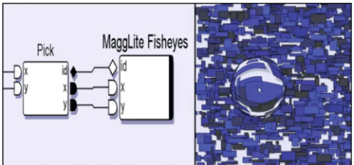
Figure 17: MaggLiteVisu application. A large dataset is displayed, with a generic fisheye connected.
More than programming ease, the strength of MaggLite is its ability to provide dynamically configurable interaction and visualization techniques without writing a single line of code. In Figure 17, one can use the toolkit pluggable fish-eye lens simply by connecting it in ICON.
RELATED WORK AND DISCUSSION
In this section we compare MaggLite with other ap-proaches. Those include programming and prototyping tools, as well as some interaction techniques close to those used in MaggLite.
Advanced GUI Toolkits
Although mainly used to develop conventional UIs, toolkits such as Garnet/Amulet [26] and Subarctic [18] have
intro-duced several advanced features to facilitate UI program-ming, such as constraint-based layout management [18]. They also describe input and event handling in a cleaner, more general and extensible way than traditional toolkits [26,15]. Even though they support at some level Post-WIMP techniques such as simple gesture recognition, they are only aware of a limited set of input devices and require significant modifications to handle any new interaction paradigm. In contrast, the palette of physical input devices and interaction techniques supported by MaggLite is very large and easily extensible due to the fine-grained architec-ture of interaction-graphs.
Post-WIMP Toolkits
Most “truly” post-WIMP toolkits are specialized into spe-cific interaction paradigms. Satin [16] for example, is a Post-WIMP toolkit which extends Swing for handling ad-vanced gesture-based techniques. Unfortunately, it only uses standard mouse events and does not handle stylus pressure and high-resolution strokes as MaggLite does with ICON advanced input handling. We nevertheless reused
Satin’s gesture interpreters in ICON, which allows us to
benefit from advantages of both tools. Jazz [7] is a Java toolkit for developing zoomable interfaces. As with Mag-gLite, user interfaces are described using scene graphs, at a fine level of granularity compared to monolithic widgets. Ubit [25] also uses scene graphs but with a “molecular” architectural metaphor: basic graphical objects (atoms) are assembled to build widgets (molecules). User interfaces are scripted rather than programmed but prototyping capabili-ties are limited as no graphical editor is available. Like CPN Tools [3] and MMM [8], Ubit handles multiple point-ing devices but is not aware of other devices and tech-niques. More generally, all previous Post-WIMP graphical toolkits support a limited set of input devices and use them quite efficiently but in ad-hoc ways.
Multi-Device Toolkits
Recent work has involved research on multi-device toolkits, especially in the fields of ubiquitous computing and aug-mented reality/virtuality [28,14,1]. So far, these approaches focused on providing unified and flexible access to a large number of devices while relying on minimalist interaction models. The Phidgets / WidgetTaps library [14] allows binding widgets to their physical counterparts. The “Patch-Panel” of the iStuff toolkit [1] allows similar de-vice/function bindings, with support for “translations” such as domain transformations. The “dynamic connection” approach used in these tools is similar to MaggLite’s. Still, interaction in most GUIs can not be merely described as button/command bindings and scaling functions. In fact, being able to adapt efficiently any device to any task re-quires using advanced interaction techniques, which in turn requires much more power and flexibility in tools. From this point of view, MaggLite goes one step beyond existing tools and shows how power and flexibility can be achieved by describing input with interaction-graphs which can be connected to scene graphs at a fine-grained level.
Interface Builders
Classical interface builders such as Visual Basic have two important drawbacks: first, they are strongly limited to WIMP interfaces. Second, while the UI appearance can be built graphically, the behaviors (including interaction) must be programmed. A number of more advanced UI building and prototyping tools have been proposed, especially with the Garnet/Amulet toolkit [26]. Most of them, like Lapi-dary [29], are graphical interface builders which use “programming by demonstration” for specifying behavioral aspects. Although powerful, this paradigm raises a number of issues that have not been addressed yet, especially when non-trivial behaviors have to be specified. Silk [24,23] is a UI prototyping tool also related to Garnet, but which uses gestures. It is a complete UI design environment with a lot of capabilities such as sketch editing, history, annotations and storyboards to specify behaviors. But UIs elements are limited to standard Visual Basic or CommonLisp widgets. Moreover, the interfaces cannot be fully tested while being built, as with MaggLite.
Graphical Behavior Editors
Constraint-based editors such as Thinglab [9] or Fabrik [20] allow specifying some behavioral parts of interactive appli-cations graphically, mainly for describing geometrical lay-outs behaviors. Control-flow approaches such as ICO/PetShop [2] use Petri Nets or State-Transition Dia-grams to describe control-intensive, highly modal parts of interactive applications. Dataflow-based editors have been used in various domains. For example, Max/MSP [27] is a widely-used graphical dataflow programming environment for musical applications. Though well-adapted for midi, audio and image real-time processing with simple standard widgets, it is not aimed at describing advanced interactions. Application of dataflow-based editors to interaction specifi-cation has been rarely exploited outside the area of 3D authoring and animation. Virtools Dev [30] uses a dataflow editor for specifying 3D input techniques interactively. Jacob’s VRED system [21] uses both a control-flow (state transition diagrams) and a dataflow editor to describe dis-crete and continuous aspects of 3D interaction. The data-flow approach has proved quite promising for describing techniques making use of multiple input devices, but as far as we know and if we except MaggLite, the only attempt to use it for describing 2D interaction has been Whizz’Ed [12]. This notation has been successfully used to specify animation and some bimanual techniques, though other techniques and input devices have not been investigated before ICON and MaggLite.
Related Interaction Techniques
Local Tools [6] describe an alternative to tool palettes in which “each tool can be picked up (where it replaces the cursor), used, and then put down anywhere on the work surface”. The KidPad [11] application uses Local Tools as well as the MID library [17] for handling multiple mice, thus allowing using multiple tools at the same time. Those features are close from MaggLite’s, although it was not
possible until now to freely associate physical devices with tools, nor to support more advanced devices such as graphi-cal tablets or 3D isometric controllers.
CONCLUSION
We presented a new Post-WIMP user interface toolkit called MaggLite. Based on a novel mixed-graph model, MaggLite successfully separates graphical and interactions parts of user interfaces. The same way as scene-graph model break monolithic graphical architectures, interaction-graphs split the heavy structure of events handling in fine-grained data-flow processing devices. This architecture allows MaggLite to improve post-WIMP interfaces design and use in terms of:
Extensibility, as programmers can easily extend the tool-kit with new graphical components and add support for new input devices and pluggable interaction techniques without heavy coding.
Flexibility, as UI designers can quickly prototype novel interfaces by using the sketch-based interface builder and the advanced interaction techniques available as pluggable components. As far as we know, MaggLite is the first UI toolkit that brings together such advanced interaction tech-niques in a fully input-independent and application-independent way. We believe this is a first step toward widespread use of techniques that are sometimes not avail-able for technical reasons more than usability ones.
Adaptability, as interfaces developed with MaggLite are fully configurable at runtime. Users can adapt applications to their abilities and to the input devices they own.
A free distribution of MaggLite and related materials are available at the URL: http://www.emn.fr/x-info/magglite/.
ACKNOWLEDGMENTS
We would like to thank Geoffrey Subileau, Mohammad Ghoniem and Narendra Jussien for their help while writing this article.
REFERENCES
1. Ballagas, R. et al. iStuff: A Physical User Interface Toolkit for Ubiquitous Computing Environments. In Proc. of CHI
'03: Human Factors in Computing Systems (April 2003, Ft.
Lauderdale, FL), ACM/SIGCHI, 2003, pp. 537-544. 2. Bastide, R., Navarre, D. and Palanque, P. A model-based
tool for interactive prototyping of highly interactive applica-tions. In CHI'02 extended abstracts on Human factors in
Computing Systems, ACM/SIGCHI, 2002, pp. 516-517.
3. Beaudouin-Lafon, M. et al. CPN/Tools: A Post-WIMP Interface for Editing and Simulating Coloured Petri Nets. In
Proc. of ICATPN'2001: 22nd International Conference on Application and Theory of Petri Nets (June 2001, Newcastle
upon Tyne, England), Lecture Notes in Computer Science, Springer-Verlag, 2001, pp. 71-80.
4. Beaudouin-Lafon, M. Instrumental Interaction: an Interac-tion Model for Designing Post-WIMP User Interfaces. In
Proc. of CHI 2000: Human Factors in Computing Systems
(2000, La Haye, Netherlands), ACM/SIGCHI, 2000, pp. 446-453.
5. Beaudouin-Lafon, M. Novel Interaction Techniques for Overlapping Windows. In Proc. of UIST 2001: 14th ACM Symposium on User Interface Software and Technology
(2001, Orlando, FL), ACM/SIGCHI, 2001, pp. 153-154. 6. Bederson, B.B. et al. Local Tools: An Alternative to Tool
Palettes. In Proc. of UIST’96: 9th ACM Symposium on User Interface and Software Technology (November 1996, Seattle,
WA), ACM/SIGCHI, 1996, pp. 169-170.
7. Bederson, B., Meyer, J. and Good, L. Jazz: An Extensible Zoomable User Interface Graphics Toolkit in Java. In Proc.
of UIST 2000: 13th ACM Symposium on User Interface and Software Technology (November 2000, San Diego, CA),
ACM/SIGCHI, 2000, pp. 171-180.
8. Bier, E.A. and Freeman, S. MMM: A User Interface Archi-tecture for Shared Editors on a Single Screen. In Proc. of
UIST’91: 4th ACM Symposium on User Interface Software and Technology (1991, Hilton Head, SC), ACM/SIGCHI,
1991, pp. 79-86.
9. Borning, A. Thinglab - A Constraint-Oriented Simulation
Laboratory. PhD thesis, Stanford University, July 1979.
Also available as STAN-CS-79-746 Stanford Computer Sci-ence Department technical report.
10. Dragicevic, P. and Fekete, J.D. Input Device Selection and Interaction Configuration with ICON. In Proc. of IHM-HCI 2001, People and Computers XV - Interaction without Fron-tiers (September 2001, Lille, France), Springer Verlag, 2001,
pp. 543-448.
11. Druin, A. et al. KidPad: A Design Collaboration Between Children, Technologists, and Educators. In Proc. of CHI’97:
Human Factors in Computing Systems (March 1997, Atlanta,
GA), ACM/SIGCHI, 1997, pp. 463-470.
12. Esteban, O., Chatty, S. and Palanque, P. Whizz'ed : a visual environment for building highly interactive software. In
Proc. of INTERACT’95: 5th IFIP International Conference on Human-Computer Interaction (June 1995, Lillehammer,
Norway), IOS Press, 1995, pp. 121-126.
13. Fekete, J.D. The InfoVis Toolkit. In Proc. of InfoVis’04:
10th Symposium on Information Visualization (October 2004,
Austin, TX), IEEE Press, 2004.
14. Greenberg, S. and Fitchett, C. Phidgets: Easy Development of Physical Interfaces through Physical Widgets. In Proc. of
UIST 2001: 14th ACM Symposium on User Interface Software and Technology (November 2001, Orlando, FL),
ACM/SIGCHI, pp. 209-218.
15. Henry, T.R., Hudson, S.E. and Newell, G.L. Integrating Gesture and Snapping into a User Interface Toolkit. In Proc.
of UIST’90: 3rd ACM SIGGRAPH Symposium on User Inter-face Software and Technology (1990, Snowbird, UT), ACM
Press, pp. 112-121.
16. Hong, J. and Landay, J. SATIN: A Toolkit for Informal Ink-based Applications. In Proc. of UIST 2000: 13th ACM Sym-posium on User Interface Software and Technology
(Novem-ber 2000, San Diego, CA), ACM/SIGCHI, 2000, pp. 63-72. 17. Hourcade, J.P. and Bederson, B.B. Architecture and
Imple-mentation of a Java Package for Multiple Input Devices (MID), Human-Computer Interaction Laboratory, University of Maryland, College Park, MD 20742, USA, 1999.
18. Hudson, S.E. and Smith, I. Ultra-Lightweight Constraints. In Proc. of UIST’96: 9th ACM Symposium on User Interface and Software Technology (November 1996, Seattle, WA),
ACM/SIGCHI, 1996, pp. 179-187.
19. Huot, S., Dumas, C. and Hégron, G. Svalabard: A Virtual Drawing Table for 3D Modeling. In Proc. of IHM’04: 16th French-Speaking Conference on Human-Computer Interac-tion (August 2004, Namur, Belgium), ACM press, 2004.
20. Ingalls, D. et al. Fabrik: A Visual Programming Envi-ronment. In Proc. of OOPSLA’88: Object-Oriented
Pro-gramming Systems, Languages and Applications (1988, San
Diego, CA), SIGPLAN Notices 23(11), 1998, pp 176-190. 21. Jacob, R., Deligiannidis, L. and Morrison, S. A Software
Model and Specification Language for Non-WIMP User In-terfaces. ACM Transactions on Computer-Human
Interac-tion, 6(1):1-46, march 1999.
22. Krasner, G.E. and Pope, S.T. A Description of the Model-View-Controller User Interface Paradigm in the Smalltalk 80 System, J. Object Oriented Programming, 1(3):26-49 (1988). 23. Landay, J.A. and Myers B.A. Interactive Sketching for the
Early Stages of User Interface Design. In Proc. of CHI '95:
Human Factors in Computing Systems (May 1995, Denver,
CO), ACM/SIGCHI, pp. 43-50.
24. Landay, J.A. SILK: Sketching Interfaces Like Krazy.
Tech-nical Video Program of CHI '96 (April 1996).
25. Lecolinet, E. A molecular architecture for creating advanced interfaces. CHI Letters. pp. 135-144. ACM Press 2003. 26. Myers, B.A. A New Model for Handling Input. In ACM
Transactions on Information Systems, 8(3):289-320, 1990.
27. Puckette, M. Combining Event and Signal Processing in the MAX Graphical Programming Environment, Computer
Mu-sic Journal, 15(3):50-57, 1991.
28. Salber, D., Dey, A.K. and Abowd, G.D. The Context Tool-kit: Aiding the Development of Context-Enabled Applica-tions. In Proc. of CHI’99: Human Factors in Computing
Systems (1999, Pittsburgh, PA), ACM/SIGCHI, 1999, pp.
434-441.
29. Vander Zanden, B.T. and Myers, B.A. Demonstrational and Constraint-Based Techniques for Pictorially Specifying Ap-plication Objects and Behaviors. In ACM Transactions on
Computer Human Interaction, 2(4):308-356, Dec. 1995.