Science Arts & Métiers (SAM)
is an open access repository that collects the work of Arts et Métiers Institute of Technology researchers and makes it freely available over the web where possible.
This is an author-deposited version published in: https://sam.ensam.eu Handle ID: .http://hdl.handle.net/10985/8329
To cite this version :
Lionel MARTIN, George MORARU, Philippe VERON - A design-for-casting integrated approach based on rapid simulation and modulus criterion - Int. J. of Product Development - Vol. 7, n°3-4, p.261-280 - 2009
Any correspondence concerning this service should be sent to the repository Administrator : [email protected]
A design-for-casting integrated approach based on
rapid simulation and modulus criterion
Lionel Martin*, George Moraru
and Philippe Véron
Laboratoire des Sciences de l’Information et des Systèmes Equipe Ingénierie, Mécanique, Systèmes
Ecole Nationale Supérieure d’Arts et Métiers 2 cours des arts et métiers
13617 Aix-en-Provence, France E-mail: [email protected] E-mail: [email protected] E-mail: [email protected] *Corresponding author
Abstract: This paper presents a new approach to the design of cast components and their associated tools. The current methodology is analysed through a case study and its main disadvantages underlined. Then, in order to overcome these identified drawbacks, a new approach is proposed. Knowing that this approach is mainly based on a rapid simulation of the process, basics of a simplified physical model of solidification are presented as well as an associated modulus criterion. Finally, technical matters for a software prototype regarding the implementation of this Rapid Simulation Approach (RSA) in a CAD environment are detailed.
Keywords: casting; integrated design; rapid simulation; feeders.
Reference to this paper should be made as follows: Martin, L., Moraru, G. and Véron, P. (2009) ‘A design-for-casting integrated approach based on rapid simulation and modulus criterion’, Int. J. Product Development, Vol. 7, Nos. 3/4, pp.261–280.
Biographical notes: Dr. Lionel Martin received his PhD at the Ecole Nationale Supérieure d’Arts et Métiers (ENSAM) in France in 2006. He is a member of the Information and System Science Laboratory (LSIS), a CNRS unit. His research activities are centred on integrated design methodologies in a design-for-casting view.
Dr. George Moraru received his PhD in 2002. He is an Associate Professor at the ENSAM and a member of LSIS, a CNRS unit. His research activities are self-excited vibration drilling, machining dynamics, and also concurrent engineering and integrated design.
Pr. Philippe Véron received his PhD in 1997. He is a Professor in LSIS at the ENSAM, where he manages a research group (IMS) on engineering, mechanics and systems. His research activity is centred on the development of geometric modelling approaches in the context of a multiview and integrated design environment. Another interest is multisite collaborative design product approaches.
1 From socioeconomical to technical context
The recent development of the foundry industry is the consequence of the conjunction of several factors. New emerging industries in China or India are changing the face of the world market. With the high-growth-rate economy and very cheap labour, they benefit from serious competitive advantages on existing industries. Like any other industry, the foundry industry is threatened though it benefits from advantages like highly skilled labour. In fact, long-experienced foundrymen are becoming infrequent because of an increasing turnover among employees. Consequently, critical tasks that often require experience and know-how cannot be realised anymore at the same quality level. Thus, in-position foundry companies are realising that improving competitiveness implies best quality, shortest delay and above all maintaining their small technological advantage. This challenge implies the use of new methodologies (Bernard et al., 2003). At the same time, numerical tools, once reserved for powerful workstations, are now available on any standard computer. This is why computer-aided tools and methodologies are gaining an ever-increasing role in the foundry industry.
Naturally, this situation of the foundry industry has been foreseen and several aspects of the design phases of cast components have already been investigated:
• The process selection can be performed efficiently thanks to a Knowledge-Based Expert (KBE) system (Er and Dias, 2000).
• Shape recognition algorithms can be used on the 3D model of the cast part for extracting surfaces for mould (Di Stefano, 1997).
• The design of runners and gates (filling system) can be assisted (Vexo, 2000; Denisa et al., 2004).
• The design of feeders can be assisted by object-oriented tools (Knight et al., 1995) or modulus-based tools (Jacob et al., 2001; Liccia and Tomasevic, 2004).
• The simulation of the cast and solidification can be made on more than 20 commercial software programs.
Presently, the situation is that various software developments have been made, and the corresponding computer-aided tools to improve productivity, created. However, these tools are rarely used. There are two main reasons for this. The first one is a purely technical limitation: the stand-alone software suffers from few linking possibilities to other everyday tools used by foundrymen. Recent case studies (Choi et al., 2002; Shuhua et al., 2003; Malaeb, 2004) investigating new methodologies conclude a lack of global integration in the design-for-casting process. The second reason is more relevant to human beings: experienced designers simply do not trust fully automatic tools. Because of this and for security reasons, the tools should only be limited to providing digital support to designers (Roucoules, 1999). The necessity of tools that work in an environment with a global view of the process has also been mentioned. One of the most advanced developments of integrated tools for foundry is Delplace’s (2004) study. However, this study is dedicated to simple-geometry steel components and its methodology cannot be extended to all existing foundry processes.
Even so, Delplace (2004) demonstrates that, in terms of competitiveness, major advances could only be made through the improvement of the tooling process design. One of the critical aspects of tooling design is the feeder design phase. It has been shown in a previous study (Martin et al., 2005) that feeder design represents a bottleneck phase for the numerical design for casting whatever the known method used: normative ‘plate equivalent’ method (CTIF, 1994), using ‘circumsphere approximation’ (Brown, 1994) or the foundryman know-how.
In this article, a new Rapid Simulation Approach (RSA) allowing the design of feeders is described as well as its implementation in CAD software.
The first point discussed is the case study that led to the study of feeders. The theoretical basics of solidification are briefly introduced and the hypothesis used for the simplified physical model of RSA presented. Then RSA is compared to existing methodology. Finally, after the description of technical matters and choices regarding the implementation, the software prototype is presented.
2 Modelling of the casting design process
This section explains the methodology we followed in order to precisely target the points that need improvement.
2.1 Description of the case study
In order to study the whole part-design process, we carried out case studies from the functional definition to the prototype. Several studies were carried out but we present only one here.
As our final goal was to create a whole integrated design environment, we used exclusively numerical tools:
• Catia v5 from the Dassault system, the well-known CAD Software, which is already an integrated environment. Thanks to its compliance with heterogeneous geometrical models and its mechanical simulation abilities, CATIA was used all throughout the study but it was useful mainly for surface and volume handling.
• PamCast 2003 from ESI Software, an industrial numerical tool for the simulation of pouring and solidification. PamCast has been used for virtual prototyping with the simulation of the manufacturing process.
• Amactif from Centre Technique Industriel de la Fonderie (CTIF) (in an older version of Liccia and Tomasevic (2004)). This software was useful for designing feeders according to CTIF methodology. This software is described in Section 2.3.2.
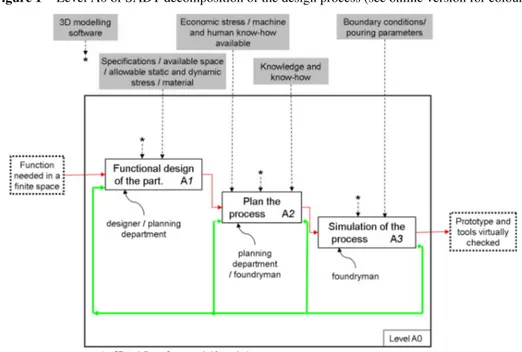
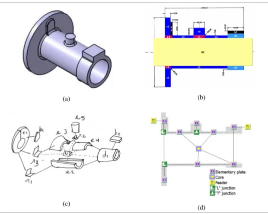
For each step of the design, we determined to which user’s technical know-how the activity was relevant: designer, planning department or foundryman. First, we made an inventory of every activity required and every model generated by the design process. Then, for each activity we determined the models needed and the models generated; thus we materialised the data flow among models. The scheme of the design process can be represented using SADT formalism; level A0 of SADT decomposition is presented in Figure 1.
2.1.1 Chronological description and models inventory
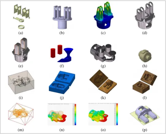
Each model cited is presented in Figure 2.
The first actor working in the design process is the part designer. The designer starts his/her design activity by specifying the functional surfaces of the part (from an assembly, for example). Therefore, the first model to come up is the functional surfaces model (a). The surfaces are then linked and thickened together in order to obtain a 3D volume model. We call it the draft model (b). The shapes of this first 3D volume model are coarse and the designer has to modify or add features in order to make them fit for the final use of the part, to reduce its mass, etc. For testing the adequacy of the functional part, mechanical and/or thermal behaviour should be simulated. The result of such simulation comes in the form of what could be called the in use behaviour model (c). Information given by this model will lead the designer to make the draft model evolve to the designer final model (d). This model shows what the part should look like at the end of the manufacturing process. In a classical organisational pattern the designer sends this model to the planning department. Up to this step, there are no compatibility problems because logistical, modelling and mechanical simulation tools are provided by a single software package (Catia v5). Therefore, passing from one step to another is trouble-free and the associative property is ensured. Once the designer final model is obtained, it serves as an information vector in the process of communication between the designer and the planning department, regardless of wherever it is. The manufacturing process planning is often integrated in the organisational structure of the design office. Nevertheless, many design offices send out only the designer final model and a planning department is integrated in the foundry division or as a distinct entity. This comes from the competence relocation issue, brought about by new concepts in collaborative engineering. The extreme case is when the designer sends the functional surfaces model
only, and the manufacturing department takes charge of all other design and adaptation processes. There is a wide range of assisting tools at this stage. Choosing the right foundry process could be made with expert rule-based software (Er and Dias, 2000). Runner and gate systems could be chosen and designed with ‘Systaver’, ‘Elisa’ or ‘Salsa’ software from the CTIF or ‘Dija’ (Denisa et al., 2004). Elsewhere, feeders could be best placed and designed thanks to ‘Amactif’ from the CTIF (Liccia and Tomasevic, 2004). The planning department has to adapt the geometry of the part to the chosen casting process. We have made here the assumption that the casting process has been chosen. Therefore, limitations related to specific casting processes have to be considered. Several shapes are impossible or difficult to obtain and the planning department will have to modify the geometry in order to make it fit the process: thickening some features, filling holes, suppressing minor features, adapting fillets, counteracting solidification, solid-state shrinkage, etc. The result of these adaptations will be the adapted part model (e). At this stage, the feeding system has to be designed. In order to place the feeders in an optimal manner, several design methodologies are available. The CTIF (1994) method is used here because it is one of the best in terms of results consistency and because a software package based on this method is available. At the same time, the runner and gate systems have to be designed, following rules expressed in Campbell (1991). The feeder system and the runner and gate systems build what we call the casting appendix model (f). The designed-for-casting model and the casting appendix model together give the pattern model (g).
Figure 2 Models generated during the design process (see online version for colours)
(a) (b) (c) (d)
(e) (f) (g) (h)
(i) (j) (k) (l)
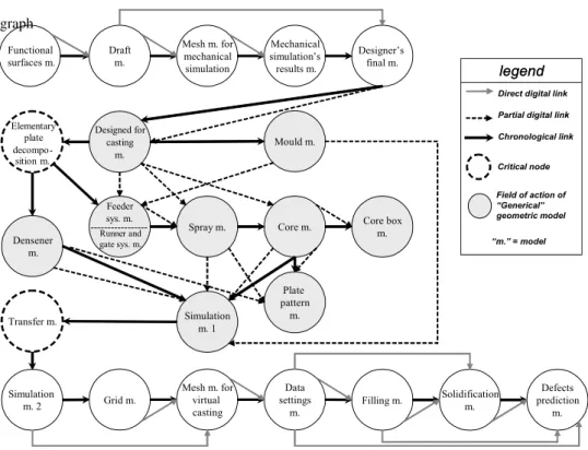
Figure 3 Design process through models classification graph
The casting model must take into account constraints concerning obstruction phenomena in the mould so that the molten metal can circulate adequately and that the elements set up can play their roles without interacting (for example, two feeders should not be too close under penalty of burning the sand separating them). The internal surfaces of the casting model cannot always be obtained by exterior mould cavities. Therefore, the core model (h) has to be created. Its geometry must also include features needed to fix it precisely and firmly in the mould. The volumetric negative of the casting model forms the pattern cavity, which will be filled by molten alloy. Therefore, this is one of the models playing a role in simulation. The simulation model (i) is nevertheless more complex, owing to the fact that the mould and sometimes core models have to be taken into account, in order to simulate heat transfer phenomena. In our case study, filling and solidification phenomena are simulated with PamCast 2003, a finite volume code for coupled CFD – thermal problems specific to foundry processes. For a die casting process, the model of the die (j) also has to be created. Using joint surfaces defined by an assisted analysis, several parts of the mould could be obtained. In our case, the green sand casting process has been chosen, therefore there is no need for a mould model. (In the sand casting process, mould is created by pouring and compressing sand on pattern plates. The mould shapes are then created without any other operation. In contrast, in the die casting process, the definition of the mould model is important because it is made of metal and has to be machined.) Tooling for the casting operation could be modelled at this stage starting from the pattern model. Moulding materials like pattern plates (k), core boxes (l) or the intermediate part of the mould should be derived in an associative manner from the pattern and mould model. The pattern plates are obtained starting from two entities:
Mechanical simulation’s results m. Functional surfaces m. Designed for casting m. Designer’s final m. Mesh m. for mechanical simulation Elementary plate decompo-sition m. Feeder sys. m. ---Runner and gate sys. m. Spray m. Core m. Draft m. Core box m. Plate pattern m. Simulation m. 1 Transfer m. Simulation m. 2 Grid m. Mesh m. for virtual casting Data settings m. Filling m. Solidification m. Defects prediction m. Densener m. Mould m. legend legend Direct digital link Partial digital link Chronological link Critical node Field of action of “Generical” geometric model “m.” = model
the joint surface (p), defined in the first stage of the process design, and the pattern model. Pattern plate models are obtained by cutting the pattern model with the joint surfaces. The simulation model has to be passed in a neutral format to the simulation software. The intermediate transfer model (m) thus appears to be a necessity. Much of the simulation setting work is needed in this model, which is critical from the consistency point of view. Various surfaces and volume entities have to be defined at this stage for preparing the process simulation (i.e., to apply the boundary conditions). Problems in model data transfer are common at this stage, which is time consuming. Meshing model and data settings models also have to be defined as support for mathematical models used in simulation.
Once simulation has been performed, two great types of results models are generated by PamCast: filling results model and solidification results model (n–o). They are not exactly geometrical models but rather data extensions using the meshing model. These results models provide support for the interpretation of physical phenomena, casting defects prediction and decisions concerning the entire design process. More than 20 models for the part have been created and handled by three different actors of the process design. We inventoried each of them in order to analyse how they were connected.
2.2 The model of the design process
In order to build a base model for studying the design process, we tried to organise the models in the previous section. Two major criteria for classification emerged: the obvious chronological moment of appearance of the model and the hierarchical dependencies between models.
Thanks to those criteria, the design process can be represented in a graph structure (Figure 3). In this graph, nodes stand for models and oriented links indicate the chronology of the design process and model flow in the design process. The model flow stands for all hierarchical dependencies between models, guaranteed by associative or consistent model manipulations.
2.3 Analysis of the model classification graph
The representation in Figure 3 shows that there are two types of problems:
1 critical nodes – There is a chronological link but no model flow link. These nodes break the continuity and the traceability of the CAD methodology. Improvements in the way that models are treated or transferred at these critical stages are to be proposed.
2 lack of consistency – We can see that nine models are linked only by nonconsistent relations, meaning that the associative property of model manipulation techniques here is not guaranteed.
These problems must be solved in order to create a continuous numerical chain. One way to improve the design process is to work on the first critical node: the elementary plate decomposition model.
The designer needs this particular model for the feeder design phase. This phase is known to be essential (Delplace, 2004) for several reasons, both technical and economical. These reasons are explained in the next section.
2.3.1 Shrinkage initiation and growth
In order to explain the way our approach runs, we need to introduce some foundry-related notions. This section deals with the metallurgical point of view of solidification phenomena and the current methodology to control them.
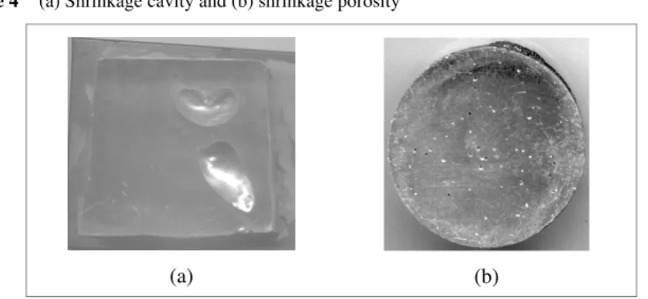
Shrinkage is the major defect in the foundry industry because it always happens in cast components. Its initiation is a direct consequence of metal solidification and contraction during cooling. Several phenomena occur during cooling and solidification of cast components (Lakhtine, 1971; Campbell, 1991; Rappaz et al., 1998). Therefore, it is necessary to predict where this defect takes place in order to avoid it. Shrinkage is a hole or cavity (Figure 4a) in a casting resulting from contraction and insufficient feed metal, and formed during the time the metal changes from the liquid to the solid state. Shrinkage size and shape depends on the part and also on several parameters such as temperature of the metal as it enters the mould, the chemical composition of the metal, the rate of cooling and subsequent heat treatments (Figure 4a–b). It is localised in zones which are the last to solidify. In order to avoid shrinkage inside the functional volume of the part, it is necessary to add a feeder or feeders. Feeders are extra sacrificial shapes stuck onto the part. Assuming they are correctly sized and placed, they will compensate for the metal leak due to contraction inside the part during solidification and thus move shrinkages inside them. Once the cast part reaches atmospheric temperature, feeders are fettled from the part, thus giving defect-free cast components.
Figure 4 (a) Shrinkage cavity and (b) shrinkage porosity
(a) (b)
Feeder design is an essential step in the casting process design (Denisa et al., 2004): these extra shapes are essential but represent masses of unproductive metal to prepare, melt and cast. The designer has to find an economical balance between the metallurgical health of the part and production costs. There are quite a few methodologies or algorithms used to assist the designer in choosing a good shape with the right size at the exact position for feeders; for example, circumsphere methodology (Brown, 1994), now abandoned for the CTIF, methodology (CTIF, 1994) described in the next section.
2.3.2 Defects prevention and feeder design with CTIF methodology
The CTIF is a European research institution dedicated to the foundry industry. Its primary roles are cooperative research and development, technology dissemination and standardisation. According to its third mission, the CTIF (1994) defined and published
a methodology for identifying and sizing required feeders for cast components. The CTIF methodology is known to be more efficient than the ‘circumsphere approximation’ and has been chosen and used by foundrymen for several years. The method consists in splitting up the part (Figure 5a–c) in platelike features, connected together by several types of joints. The idea is to look for the ‘hot spots’, i.e., the last areas of the part that remain as liquid as the surrounding volume becomes solid, by tracking the variation in solidification time among these elementary plates (Figure 5d). This is made on the basis of a simplified thermal analysis (Chworinoff, 1940; Sciama and Jeancolas, 1971) taking into account geometrical parameters (with empirical correction) and the thermal connection of each elementary plate. Once the hot spots are located, feeder or chill elements will be linked to them. The CTIF recommends Amactif, a user guide software, for this methodology (Liccia and Tomasevic, 2004) in order to ease its use. But the splitting phase of the part remains and still has to be done by hand. As it demands manual intervention for a nondeterministic decomposition, this methodology has two major limitations: it is not possible to implement it ‘as is’ to the CAD environment and its efficiency depends on user’s know-how. This is the reason why the feeder design phase with elementary plate decomposition corresponds to a ‘critical’ node (Figure 3). Therefore, even if such an integration has been partially carried out (Knight et al., 1995; Jacob et al., 2001) and even if a software based upon it has been commercialised (Liccia and Tomasevic, 2004), a new approach has to be used for feeder design. Section 3 introduces a formal physical/thermal background for new tools that we need and Section 4 presents a new approach that improves the actual design process.
Figure 5 Key steps in CTIF methodology (see online version for colours)
(a) (b)
3 Requirements for the numerical simulation
Owing to the highly complex phenomena involved, simulation of the casting process is computationally time consuming. Consequently, the diffusion of these tools occurred only a few years ago, when computers reached sufficient power. This section presents the phenomena involved and the mathematical model associated.
3.1 The solidification phenomenon
Nowadays commercial software usually treats the simulation of the casting process in two separate steps: filling and solidification. In contrast to what this organisation imagined, the solidification of the alloy depends on phenomena initiated during the filling of the mould. During the filling, the liquid alloy already starts to cool and this loss of temperature depends on the length of the path it takes inside the mould. Therefore, coupled thermal-filling mathematical models have to be considered. At the end of the filling, the alloy presents a nonuniform field of temperature. This field is the initial state for solidification simulation. Several phenomena are involved in the solidification phase:
• Heat conduction inside various domains: alloy (liquid or solid), mould, chills. The physical phenomenon of heat conduction is modelled with the general heat conduction equation.
• Heat convection and radiation among alloy, mould and chills but also ambient atmosphere. These phenomena are usually integrated using limits conditions to the general heat transfer equation.
• Latent heat of fusion phenomenon due to the transformation of liquid alloy to its solid state inside the alloy and all along the solidification front. In order to take this into account, we use the “mean pseudo specific heat” (Rappaz et al., 1998) approach determined with the local gradient of the solid-state fraction.
• Convective transport of material inside liquid alloy due to both filling residual flow and heat gradient. Navier-Stokes equations are required to take this into account. • Solute diffusion, according to chemical composition. It is possible to foresee the
microstructure of the solidified alloy with the simulation of this phenomenon (Chao and Du, 1999). As it occurs at a microscopic scale, it demands microscopic elements for numerical simulation. Therefore, as we study solidification of the part, which is a macroscopic phenomenon, we cannot take this into account without huge simulation computational time.
3.2 Hypothesis used for rapid simulation and simplified model
Every physical model for these phenomena is based on differential equations with mostly geometry-dependent parameters. Nevertheless, taking into account all phenomena at the same time is difficult, time consuming and useless regarding the aim of our study. Once the simulation time can be made to last just a few minutes, an interactive use of the tool
will be possible for the designer. Several assumptions (CTIF, 1994) can be made (and are made by the CTIF for its methodology) in order to handle a simplified mathematical model allowing increasing the speed of simulation computation:
• Solidification starts with a constant field of temperature. This assumption is always verified in sand casting, but for die casting, it supposes an efficient runner and gate system in order to have a rapid filling.
• Heat transfer between mould and cast part is considered as a constant heat flow normal to the frontier surface between the two entities.
• Convective flows are neglected. Owing to the viscosity of liquid alloy during solidification, they do not play an important role at a macroscale.
• Solute diffusion is neglected. It allows prediction of chemical composition but does not intervene at a macroscale on heat phenomena.
According to these assumptions, a simplified model can be formulated as a heat conservation equation assuming latent heat transfer (Rappaz et al., 1998):
2 ( ) ( ) ( ) . ( ) all all all T dfs T T Cp T L T T dT t ρ λ ∂ ⎛ − ⎞⋅ = ∇ ⎜ ⎟ ∂ ⎝ ⎠ (1)
In order to easily implement our model in dedicated software, we use an enthalpy formulation. So Equation (1) can be expressed as:
( all( ). ( )) 0.
div T grad T
βD− λ = (2)
Considering the preceding assumption, the limits conditions for solving Equation (2) are just a thermal flow on the surface of the alloy. One will consider limits conditions of mixed Cauchy type that corresponds to natural convection:
. . .( ext ) T T n h dS T T n ∂ = ∇ = − ∂ JG G (3) where, for Equations (1), (2) and (3):
all = alloy Cp = specific heat ext = external
fs = solid fraction
h = heat transfer coefficient L = latent heat
n = local vector, normal to S S = surface of the part
t = time T = temperature β = volumic enthalpy λ = thermal conductivity ρ = density ∇ = Nabla operator.
The results from solving these equations also depend on the geometry: shape, size, local thickness, etc. The CTIF methodology takes geometry into account only through a global shape coefficient which supposes strong assumptions on the above-cited phenomena. Our approach is based on the same assumptions but takes the real geometry of the cast component into account through its meshed model. Heat transfer phenomena are also better accounted for. The rapid simulation approach is less restrictive than the CTIF methodology.
4 The rapid simulation approach proposed
The main idea with rapid simulation is to use the simplified model presented in the previous section in order to quickly predict the behaviour of the casting part designed. Hence, the designer, even though inexperienced in casting, can prevent defects in the part by first adding and then modifying feeders and/or shapes to the part interactively.
4.1 Overall rapid simulation methodology
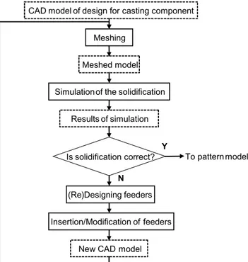
The methodology is iterative. The first rapid simulation offers primary indications on defects existence on the cast component and a rough evaluation of the size of feeders needed. Then the designer adds feeders and restarts the rapid simulation. This first iteration allows verifying feeding system efficiency. If negative, the designer modifies feeders and/or the cast component and restarts. This approach is close to what foundrymen actually practise but on real prototypes. Because several iterations could be necessary to create an efficient feeding system, the rapid simulation indeed has to be rapid.
Figure 6 Rapid simulation methodology scheme
CAD model of design for casting component Meshing
Meshed model Simulationof the solidification
Results of simulation
(Re)Designing feeders Insertion/Modification of feeders
New CAD model
Is solidification correct? To pattern model
Y
About the ‘correct solidification’ criterion in Figure 6, a feeder system is said to be correct or efficient if it respects several design rules defined in Campbell (1991). The two main feeding rules are as follows:
1 The feeder must solidify at the earliest at the same time as the casting; later is better (heat transfer criterion).
2 The feeder must contain sufficient liquid alloy to compensate for the volume contraction of the casting; more is safer (volume criterion).
4.2 Searching for hot spots
The phase that must be investigated for placing and sizing feeders is the end of solidification. As we explained in Section 2.3.1, shrinkages are localised in zones which are the last to solidify. The last zones to solidify in the cast component indicate where feeders are needed. These zones are called ‘hot spots’. But the simulation is made on a meshed model so we use the ‘polyhedral translation’ of this criterion: those elements of the part needing feeders are the last ones remaining liquid as surrounding elements become solid. Rule 1 in Section 4.1 can be satisfied by ensuring that each hot spot tracked by rapid simulation is localised inside a feeder’s volume.
4.3 Validation and benchmarking of the rapid simulation approach for hot spots tracking
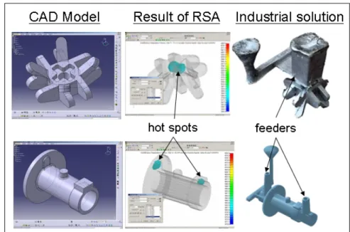
The previous sections explain the basics. In order to verify that our approach correctly situates hot spots, we led several case studies on cast components for which we knew the industrial feeder’s system model. Two of them are represented in Figure 7.
In the first column, the initial CAD models are represented. In the second column the results of the RSA are represented: hot spots are revealed through the observation of the liquid fraction of the alloy in the final step of solidification. Then in the final column the industrial solutions, supposed to be efficient, are shown. What is remarkable in this figure is that the positions of feeders in the last column are well placed according to the results of the RSA in the second column.
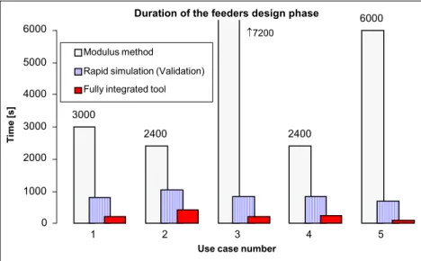
Once the efficiency of the RSA has been proved, it has to be evaluated. Before implementing this new approach, we had to compare it to existing methodology. Before starting the development of this approach inside an integrated environment, the efficiency was evaluated. Details of the experiments such as software used and use cases method are given in Martin et al. (2005). Results of this evaluation are presented in Figure 8.
Figure 8 Comparison of durations between the traditional modulus method, the RSA and perspectives for a fully integrated tool (see online version for colours)
This histogram represents, for each of the five use cases studied, the time needed in seconds for the modulus method, for the RSA’s experiments and for the integrated RSA. PamCast Simulations are made on Intel P4 @ 1,5 GHz 512 Mb DDRam with Win 2000, version 2003; Alloy: AFNOR AS7G; Initial temperature 700°C; Implicit mould 10 cm; and 20°C ambient temperature.Indicated times for the CTIF methodology were obtained from a human expert in casting design. The distinction between the last two categories comes from the time needed for files and data manipulation, conversion and transfer, according to the software used. This time is omitted for the last category. In this figure, the potential gains for fully integrated RSA encourage us to perform the implementation.
5 Integration into a CAD environment
Experiments such as in Choi et al. (2002) showed that even if computer-aided tools reach a real technical efficiency, they remain useless if they are not implemented inside the usual working environment of the end user. That is why we wanted to create an
3000 2400 2400 6000 0 1000 2000 3000 4000 5000 6000 1 2 3 4 5
Use case number
Ti
m
e [s]
Modulus method
Rapid simulation (Validation) Fully integrated tool
↑7200
integrated tool. We chose to implement it in CATIA because it is already an integrated design environment for mechanical design with all functionalities of creation and manipulation of 3D models and because it offers open programming facilities. This section describes technical obstacles that had to be overcome in order to implement the Application Program Interface (API) in the CAD environment. They are presented in a chronological timeline corresponding to the point they appear in the methodology.
5.1 Mesh-type choice
One of the major choices is the mesh type. PamCast, the commercial software used for the validation of the approach, handles finite volume elements (QUAD8).
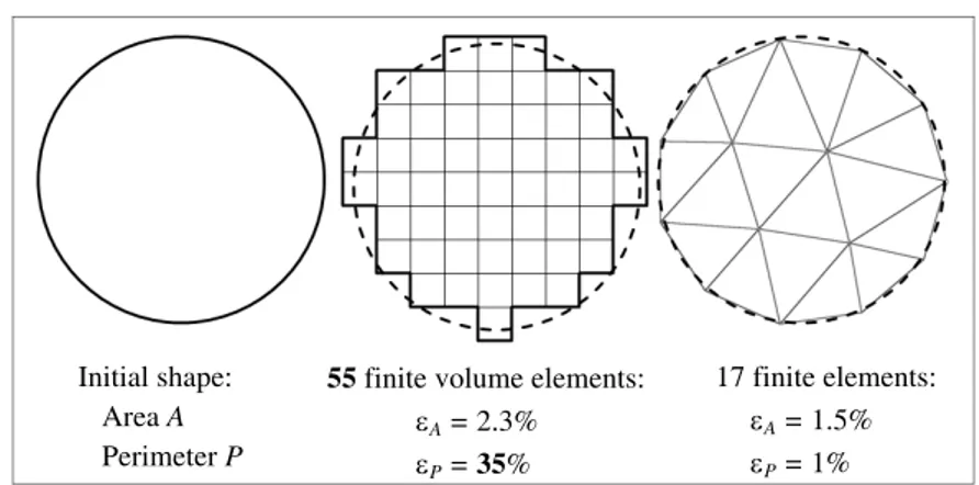
The main disadvantage of these types of elements is that they induce a very important geometrical approximation. Figure 9 illustrates this assertion. From the perfect circle on the left, finite volumes and finite elements meshes are compared in terms of area, perimeter approximation and number of elements. Considering three-dimensional geometries, the figures are probably different but this simple example in two dimensions gives the idea of the problem induced by finite volume meshes. Precisely, thermal simulation highly depends on the surface area, as thermal flow depends on it. That is why PamCast operates a surface correction after the mesh – to artificially maintain a low area approximation while altering the shape of the part. Additionally, finite volume meshes generate more elements, inducing even longer computational time. For these reasons, a built-in CATIA mesher and Code Aster, a free open-source finite element solver that handles finite elements TETRA4, have been chosen.
Figure 9 Influence of mesh choice: area and perimeter approximation
Initial shape: Area A Perimeter P
55 finite volume elements: εA = 2.3%
εP = 35%
17 finite elements: εA = 1.5%
εP = 1%
5.2 Rough maximisation of solidification time
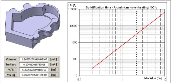
Before starting numerical simulation, in order to foresee precisely the solidification time for hot spots, we need to know approximately the overall time of solidification of the cast part. We use for this the results of Sciama and Jeancolas (1971), which give us, for each type of alloy, the upper limit of solidification time for a given modulus.
This evaluation is made by calculating the modulus of the perfect sphere with the same volume. The volume of the part is easy to compute in a CAD environment whatever its shape and complexity. For example, Figure 10 presents an aluminium cast part whose
volume is equal to 1266 cm3. The modulus of the sphere with this volume is 2.23 cm. Then, according to the graph, its solidification time is less than 3000 s. This approximation allows us to adjust and then launch the rapid simulation more efficiently.
Figure 10 Solidification time evaluation using global modulus (see online version for colours)
5.3 Postprocessing the solver’s results
Once the solver has performed the simulation, the results are available only in a raw data format. Typically, Code Aster’s results look like a list of temperatures corresponding to each step of calculation and repeated as many times as there are points in the meshed model. This result file often reaches the size of 1 Gb and, like for other tasks, has to be analysed as quickly as possible. In order to search hot spots among this list, we apply the following treatments. From the whole file, a simpler list is built with only the point P by its coordinates and the time t elapsed until it reaches the temperature of the alloy solidus. The new data to work on is a list of {Pi,ti} with i taking each value from 1 to the number of points in the meshed model. Then, the neighbourhood table between points Pi and Pj is written thank to the meshed model file: Pi and Pj are neighbours if they belong to the same mesh element and [PiPj] is said to exist.
Then, the algorithm uses the reciprocal condition of the rule stated in Section 4.2:
{ , } { , } { , }/( [ ] ).
P Pi ti P t′ ′ Pi ti PP AND t′ ′ t
∀ ∈ ∃ ∈ ∃ <
If this assertion is true then P is not a hot spot and is then suppressed from the initial list. Instead of a repeated long search among all points, points are rapidly erased from the list, resulting in a treatment of only a few seconds. The final result of the treatment is a reduced list {Pj,Tsj} where each Pj is a hot spot and Tsj its solidification time.
5.4 Choosing the feeder’s shape
As there exist tools for process selection for cast components (Er and Dias, 2000), we try to implement a Knowledge-Based Expert (KBE) system to select which type of feeder is the most appropriate. For giving a proposal, the KBE needs information,
‘facts’ which can be either automatically ‘linked’ (part size, material, etc.) or explicitly given by the designer (high quality, number of units, etc.). Such a KBE has been developed (Figure 11).
Figure 11 KBE for feeder’s shape selection (see online version for colours)
Nevertheless, the feeder’s shape mainly depends on each foundry’s habits. Since the KBE gives only simplistic information on the cast components, it has not yet been implemented in the environment.
5.5 Feeder’s size evaluation
Knowledge of feeders’ position is essential but not sufficient. As we said in the preceding section, knowing the phase of the end of solidification is useful because it not only gives hot spots localisation but also the time these zones take to solidify, Ts, indicating the needed size of the feeders stuck to them according to Chworinoff’s (1940) rule:
2 V Ts k A ⎛ ⎞ = ⎜ ⎟⎝ ⎠ (4) where:
k = unique proportional coefficient for a given alloy and mould material V = cast part volume
A = area.
The coefficient k can be determined theoretically and can also be easily evaluated experimentally.
Equation (4) allows a rough evaluation of the feeders’ size. As our approach is iterative, we can accept this because inappropriate dimensions will be modified in the next iterations. But for this, we need to parameterise the feeders’ shape. We choose a basic cylindrical shape with a length-to-height ratio of 1 for its simplicity and efficiency whatever the alloy. It is written:
6 ti di k ⎛ ⎞ = ⎜⎜ ⎟⎟ ⎝ ⎠ (5)
where di is the diameter of the feeder corresponding to the hot spot Pi solidified at ti. Once a feeder is designed for each hot spot, one more verification has to be made. Rule 2 in Section 4.1 is satisfied by ensuring that all feeders have sufficient volume to feed all the shrinkage. The sum of all feeders’ volumes should be at least equal to the minimum volume, given by:
min casting V V β ε β = − (6) where:
β = ‘shrinkage factor’ depending on the alloy
ε = ‘feeding efficiency’ depending on the feeders’ shape.
5.6 Integrated prototype
Schematically, the API developed has to make the operator interact with two major elementary entities: the CAD system and the thermal solver. For the CAD environment, we choose CATIA V5 from the Dassault System for its programming facilities and its wide range of data exchange possibilities. For the solver, Code Aster was one of the rare free open-source codes allowing computing for derivative, nonlinear, time-dependant problems. Figure 12 shows how the API is situated and what type of data it has to handle. The main graphical interface has been developed in VBA but singular key features such as mesh conversion or postprocessing that need low-level rapid treatment have been developed in C. The API is not just an interface converting data and files: it also triggers, synchronises and supervises operations occurring inside the CAD environment.
In concrete terms, our tool consists of an additional window coming at the front of the standard software interface. The various steps of design from alloy definition, through simulation to feeder’s insertion, are organised chronologically in order to give a ‘wizard’ style to this computer-aided tool. For data required in the field, such as overheating, for example, the tool advises a default value as often as possible but always allows the operator to modify it according to his/her needs and/or experience. Figure 13 presents two screen captures corresponding to two different phases of design.
Figure 13 Screen captures of the implemented tool (see online version for colours)
6 Conclusion
For obvious reasons, nowadays the context of the foundry industry encourages the use of computer-aided methodology: in order to speed up design, improve quality, keep an associative link and maintain the global consistency and the traceability of the process, and finally optimise the overall design. Our final goal is to create such an integrated design-for-casting environment. From an extensive case study, a key phase has been identified in cast component design: the design of feeders. As a first step to the whole integrated environment, this narrow phase has been integrated. For this, a new approach based on rapid simulation had to be used. In this article, theoretical basics of this new RSA have been detailed. Concerning the practical difficulties encountered, the choices made to overcome them have been explained. Finally, the view of the final operating API has been shown. Unfortunately, because of the use of a noncommercial thermal solver, the simulation duration does not fit our expectations and extends the overall time needed for this approach. The potential gains expected in Section 4.3 (Figure 8) have not yet been reached. A new development with an optimised solver is to be done. However, the realisation of this software prototype allows us to finalise its global architecture. This modular architecture will ease the upgrade of API. A more efficient solver could be simply implemented, like an update of the older one, and other design-for-casting functions will also be integrated in this API such as the modelling of runner and gate systems as well as a global optimisation tool.
References
Bernard, A., Delplace, J-C., Perry, N. and Gabriel, S. (2003) ‘Integration of CAD and rapid manufacturing for sand casting optimisation’, Rapid Prototyping Journal, Vol. 9, No. 5, pp.327–333.
Brown, J. (1994) Foseco Foundryman’s Handbook, Butterworth-Heinemann, ISBN 0750619392. Campbell, J. (1991) Castings, Oxford: Butterworth-Heinemann, ISBN 0750647906.
Centre Technique Industriel de la Fonderie (CTIF) (1994) Masselottage en moulage sable, Éditions techniques des Industries de la Fonderie, ISBN 2711901556.
Chao, L-S. and Du, W-C. (1999) ‘Macro-micro modelling of solidification’, Proc. Natl. Sci. Counc.
ROC(A), Vol. 23, No. 5, pp.622–629.
Choi, J.C., et al. (2002) ‘A study on development of a die design system for die casting’, Advanced
Manufacturing Technology, Vol. 20, No. 1, pp.1–8.
Chworinoff, N. (1940) ‘Theorie der Erstarrung von Gusstucken’, Die Gießerei, June.
Delplace, J-C. (2004) ‘L’ingénierie numérique pour l’amélioration des processus décisionnels et opérationnels en fonderie’, Thèse de doctorat, Nantes, France.
Denisa, L., Gardan, Y. and Perrin, E. (2004) ‘A framework for a distributed CAD system’, Int.
Jour. Computer-aided Design, No. 36, pp.761–773.
Di Stefano, P. (1997) ‘Automatic extraction of form features for casting’, Computer-aided Design, Vol. 29, No. 11, pp.761–770.
Er, A. and Dias, R. (2000) ‘A rule-based expert system approach to process selection for cast components’, Knowledge-based Systems, No. 13, pp.225–234.
Jacob, E., Praveen, B., Sasikumar, R. and Gopalakrishna, V. (2001) ‘Feeder design for castings using a CAD package’, Indian Foundry Journal, Vol. 47, No. 10, pp.17–21.
Knight, B., Cowell, D. and Preddy, K. (1995) ‘An object-oriented tool for the design of casting procedures’, Engng. Applic. Artif. Intell., Vol. 8, No. 5, pp.561–567.
Lakhtine, I. (1971) Métallographie et traitement thermiques des métaux, Cote: 546,3,LAK, Editions MIR, Moscou.
Liccia, Y. and Tomasevic, D. (2004) ‘Amactif XP – un outil de calcul des systèmes de masselottage en moulage sable’, Fonderie fondeur d’aujourd’hui, October, No. 238, pp.6–7. Malaeb, B. (2004) ‘Integrating computer simulation of solidification in design process of feeding
systems of castings’, 3rd Faculty of Engineering and Architecture Student Conference, Beirut, Lebanon, 27–28 May.
Martin, L., Moraru, G. and Veron, P. (2005) ‘Structured CAD/CAM models in casting process design’, III International Conference on Advances in Production Engineering, Varsovie, Poland, Vol. 3, pp.151–160.
Rappaz, M., et al. (1998) Traité des matériaux No 10 : Modélisation numérique en science et génie
des matériaux, EPFL, ISBN 2880743656, pp.211–258.
Roucoules, L. (1999) ‘Méthodes et connaissances: contribution au développement d’un environnement de conception intégrée’, Thèse de doctorat de l’Institut National Polytechnique de Grenoble, Spécialité: Mécanique: Conception, Géomécanique et Matériaux, 24 September. Sciama, G. and Jeancolas, M. (1971) ‘Temps de solidification de pièces élémentaires coulées
en sable – Coefficients de forme et calcul pratique des masselottes’, Fonderie, No. 303, pp.239–250.
Shuhua, Y., Guoxiang, W., Fei, Y., Yixin, W. and Jiangbo, Y. (2003) ‘Application of an integrated CAD/CAE/CAM system for die casting dies’, Journal of Materials Processing Technology, No. 139, pp.465–468.
Vexo, F. (2000) ‘Contribution à l’intégration de la simulation avec la CAO: application à la construction du système de remplissage en Fonderie’, Thèse de doctorat, Reims.