HAL Id: hal-01959533
https://hal.archives-ouvertes.fr/hal-01959533
Submitted on 21 Jan 2019
HAL is a multi-disciplinary open access
archive for the deposit and dissemination of
sci-entific research documents, whether they are
pub-lished or not. The documents may come from
teaching and research institutions in France or
abroad, or from public or private research centers.
L’archive ouverte pluridisciplinaire HAL, est
destinée au dépôt et à la diffusion de documents
scientifiques de niveau recherche, publiés ou non,
émanant des établissements d’enseignement et de
recherche français ou étrangers, des laboratoires
publics ou privés.
Sean O’Duill, Stuart Murdoch, Liam Barry, Pascal Besnard
To cite this version:
Mohamed Omar Sahni, Stephane Trebaol, Laurent Bramerie, Michel Joindot, Sean O’Duill, et al..
Frequency noise reduction performance of a feed-forward heterodyne technique: application to an
actively mode-locked laser diode. Optics Letters, Optical Society of America - OSA Publishing, 2017,
42 (19), pp.4000-4003. �10.1364/ol.42.004000�. �hal-01959533�
Frequency noise reduction performance of a
feed-forward heterodyne technique: application to an
actively mode-locked laser diode
M
OHAMEDO
MARS
AHNI1,2,*, S
TÉPHANET
REBAOL1, L
AURENTB
RAMERIE1, M
ICHELJ
OINDOT1, S
EANO’D
UILL2, S
TUARTG. M
URDOCH3, L
IAMP. B
ARRY2,
ANDP
ASCALB
ESNARD11UMR FOTON, CNRS, Université de Bretagne-Loire, Université de Rennes 1, Enssat, 6 rue de Kerampont, CS 80518, F22305 Lannion, France 2Radio and Optical Communication Lab, School of Electronic Engineering, Dublin City University, Glasnevin, Dublin 9, Ireland
3Dodd-Walls Centre for Photonic and Quantum Technologies and Department of Physics, The University of Auckland, Auckland 1020, New Zealand *Corresponding author: [email protected]
Compiled May 17, 2017
We report on the frequency noise reduction perfor-mance of a feed-forward technique. The study is based on frequency noise measurements that allow the trans-fer function of the feed-forward loop to be determined. The main limitation to the noise compensation is at-tributed to the local oscillator flicker noise and the noise added by the optoelectronic loop elements. The technique is applied to an actively mode-locked laser diode demonstrating, at the output of the system, an optical frequency comb source with 14 comb-lines re-duced to sub-kHz intrinsic linewidth. © 2017 Optical Society of America
OCIS codes: (060.1660) Coherent communications, (060.2840) Heterodyne,(140.3295) Laser beam characterization, (140.5960) Semi-conductor lasers, (140.4050) Mode-locked lasers
http://dx.doi.org/10.1364/ao.XX.XXXXXX
Coherent optical frequency combs (OFCs) with a low comb-line frequency noise are highly attractive for a wide applica-tions ranging from time and frequency metrology [1] to astron-omy and space science [2] through optical communications [3], millimeter-wave generation and frequency-comb spectroscopy [1]. Many techniques have been demonstrated to generate OFCs e.g. using gain switching of discrete mode lasers [4], Kerr effect in non-linear microresonators [5], cascaded intensity or phase modulators [6], and mode-locked laser diodes (MLLDs) [3] to name only a few.
Mode-locked laser diodes have been specially identified as a potential source for compact and cost-effective future frequency comb systems [7]. Nevertheless their performances in terms of noise still remain limited. Concerted theoretical studies and experimental investigations have then been performed to un-derstand the noise properties in such lasers [8–12]. As a result, the main limitations in using semiconductor MLLDs for cer-tain applications such as coherent optical communications and millimeter-wave generation have been determined to be: i) the
pulse-to-pulse timing jitter defined as the pulse envelope’s tem-poral deviation of the optical pulse train ii) the frequency noise of individual optical modes, which contributes essentially to their optical linewidth [10].
Passively semiconductor MLLDs are known to generate rel-atively stable optical pulse trains without the help of external reference. However, for more demanding applications such as clock recovery, this timing jitter is usually inadequate, requiring some stabilization. Active mode-locking of such sources has been demonstrated to stabilize their timing jitter, making their comb lines highly correlated [11]. In terms of phase or frequency noise, it is also known that individual lines derived from a semi-conductor MLLD exhibit a large optical linewidth from a few to hundreds of MHz [13]. When used for coherent optical trans-mission with high-order modulation formats for example, such optical linewidth levels induce, amongst others, a high penalty in terms of bit error rate [14]. Unlike the timing jitter, there is a significant lack of techniques to reduce the comb-line optical linewidth.
Recently, we have shown the proof-of-concept of a feed-forward heterodyne (FFH) technique for optical linewidth re-duction on a passively mode-locked laser diode [15]. We have demonstrated the possibility to use the optical mixing between a narrow-linewidth single-mode laser and only one optical mode from the OFC to generate a correction RF signal through a het-erodyne detection. Intrinsic optical linewidth reduction over 16 lines from almost 20 MHz to below 300 kHz has been obtained using a reference laser with 29 kHz linewidth. However experi-mental results have shown imperfect linewidth compensation because the OFC lines exhibit slightly different phase noises due to the timing jitter of the pulses from the passively MLLDs [12].
In the present letter, we extend investigations on the feed-forward technique to achieve enhanced performance in terms of FM noise reduction. Instead of performing traditional optical linewidth measurements, we study the frequency noise charac-teristics in detail. This approach allows for the measurement of the frequency noise spectral density of the feed-forward signals, and yields important insights into the limiting factors of the noise reduction performance of the system. We also applied the
Local Oscillator RF Amplifier Bias Tee RF Synthesizer Local Oscillator VOA Balanced Receiver 10 % 50 % 50 % Controller PC Delay Line Measurement
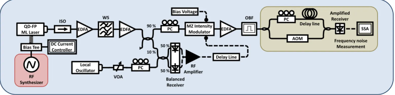
Fig. 1.Experimental set-up of the feed-forward heterodyne compensation coupled to an actively mode-locked laser, followed by the frequency noise measurement bench. Abbreviations are as follows. PC: Polarization Controller, VOA: Variable Optical Attenuator, EDFA: Erbium Doped Fiber Amplifier, ISO: Isolator, WS: WaveShaper, OBF: Optical Bandwidth Filter, AOM: Acousto-Optic Modulator, SSA: Signal Source Analyzer.
FFH scheme to an actively MLLD in this work and evaluated the frequency noise compensation.
The paper is organized as follows: first, we describe the ac-tively mode-locked laser used to generate the low timing jitter OFC. Second we review the principle of the feed-forward het-erodyne technique and present the experimental setup; third we apply the technique to a single comb-line and then extend the noise reduction procedure across the entire OFC. We report a significant frequency noise reduction over 21-comb lines limited by the local oscillator frequency noise. It corresponds to an in-dividual intrinsic optical linewidth less than 4 kHz for all the 21 lines over a bandwidth greater than 800 GHz. Moreover, it is important to mention that 14 among them exhibit a sub-kHz linewidth.
Experiments have been carried out using a quantum dash Fabry-Perot (QD-FP) MLLD with a free spectral range (FSR) νFSRof 42.7 GHz. A temperature probe, a Peltier cooler and a micro-wave V-type connector have been integrated with the semiconductor laser chip into a butterfly package. The measured threshold current is 19 mA. In all the experiments the laser was driven by a DC current of 160 mA and held at a constant temperature of 25°C. The optical spectrum at the MLLD output exhibits a flat profile centered at 1553 nm and comprising almost 30 longitudinal modes within a -3 dB bandwidth of 10.6 nm. An exhaustive description of the device structure, including its optical spectrum, is available in [16].
To reduce the timing jitter, an active mode-locking process using a straightforward technique has been set up. It consists in locking the MLLD frequency repetition rate to a highly co-herent microwave/RF source. Concretely, a +21 dBm power modulated RF signal at 42.7 GHz has been used to directly drive through a bias tee the DC injection current. A significant narrow-ing of the fundamental RF beat note in active locknarrow-ing case has been observed [17], proving that the timing jitter is successfully reduced. By actively locking our device, we induce a strong phase-correlation between optical modes. In other words as it will be shown in this paper, we guarantee similar intrinsic optical linewidth for all optical modes, which is a key issue for the rest of investigations concerning the feed-forward technique. The experimental arrangement is depicted in figure1. The active MLLD output is first coupled to an optical isolator for sup-pressing back-reflections, amplified through an Erbium doped fiber amplifier (EDFA) and then sent to a programmable optical
filter allowing twenty one lines to be selected. The 21-line comb is amplified through a second EDFA before being split by a 90/10 optical coupler. 90% of the power is sent through a polarization controller to a Mach-Zehnder intensity modulator (MZM) while 10% is mixed with a local oscillator (LO), through a balanced receiver. The LO is a tunable laser, based on high quality factor whispering-gallery-mode microresonator, providing an intrinsic optical linewidth less than 30 Hz [18]. A polarization controller is also used to ensure an efficient mixing. The LO is correctly detuned with respect to the central comb-line by about 10 to 15 GHz. The beat signal with the adjacent mode, that is 25 to 30 GHz away as well, is outside the bandwidth of detector and RF amplifier. The latter signal is then amplified and used to feed the modulator through an electrical delay line. The modulator is biased at the null transmission thanks to a DC voltage source, to ensure a linear operation. An EDFA is set at the MZM output to amplify the signal before performing characterizations.
The basic principles of this technique will be briefly recalled through an analytical analysis considering only the central opti-cal mode. Since our main purpose is to study the phase noise, we omit the amplitude terms in the following model. Let E0(t) and ELO(t)be respectively the electric fields of the central line and the local oscillator:
E0(t)∝ ej(2π f0t+φ0(t)) (1)
ELO(t)∝ ej(2π fLOt+φLO(t)) (2)
where f0, φ0(t)and fLO, φLO(t)are respectively the optical fre-quency and phase noise of the central mode and the LO. The heterodyne detection provides a photocurrent expressed as:
ipd(t)∝ cos[2π∆ f t+ (φ0(t) −φLO(t))] (3) where∆ f is the frequency detuning between the two sources. When using this signal to drive a MZM modulator through which a part of the central line signal is passed, two optical components are generated on either side of the input signal [15]: EUSB(t)∝ ej[2π( f0+∆ f )t+(2φ0(t)−φLO(t))] (4) ELSB(t)∝ ej[2π( f0−∆ f )t+φLO(t)] (5) The upper side-band (USB) exhibits twice the initial phase noise of the central mode, whereas the lower one (LSB) contains only the local oscillator phase noise, which is the phase-compensated
line of interest. A detailed description of the analytical model is available in [13].
A full characterization of the central comb-line can be achieved using a frequency noise measurement bench (see Fig.1). To perform the frequency noise characterization, a classical method based on a correlated delayed self-heterodyne technique has been used [19]. A Mach-Zehnder interferometer (MZI) is used as an optical discriminator, which converts the frequency fluctuations ν(t)of the input laser into phase fluctuations∆φ(t) carried on a low phase noise RF wave. The power spectral den-sity (PSD) of the phase fluctuations is measured using a phase noise analyzer and related to the frequency fluctuations PSD of the laser by:
S∆φ(f) = [2πτsinc(π f τ)]2Sν(f) (6)
S∆φ(f)equals Sν(f)multiplied by a gain(2πτ)2, proportional
to the square of the delay fiber length τ inserted in the MZI, when f remains small compared to τ−1(sinc function equals approximately one). The PSD detection bandwidth is limited by the first zero of the sinc function localized at fc= 1τ, a trade-off has then to be found between gain and bandwidth detection of the frequency noise PSD with respect to the introduced delay τ.
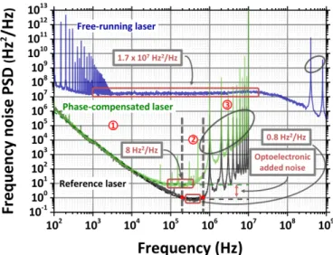
Fig. 2. Frequency noise PSDs of: the central comb-line before the FFH system (blue curve), the central comb-line after the FFH system (green curve) and the local oscillator (black curve). The environmental noise observed on the free-running laser PSD (100 Hz< f <4kHz) is caused by the power supply line interference (50 Hz and its harmonics artifacts). Circled peaks in region 3 correspond to the MZI free spectral range and its harmonics (for a delay fiber length of 200 m).
Usually, different contributions can be distinguished in the fre-quency noise PSD: i) the low-frefre-quency FM noise for which the origin is still an open discussion ii) the white FM noise arising from the laser phase fluctuations induced during the sponta-neous emission process. Theoretically, the FM noise PSD can then be described by the relation:
Sν(f) = kr f2 + kf f + δν π (7)
where kr(Hz3) and kf(Hz2) are constants related to the strength of the random walk FM noise and the flicker FM noise, respec-tively [19]. Generally, the laser line shape is described by a Voigt
profile, which is the convolution between a Gaussian line shape, induced by the low-frequency FM noise, and a Lorentzian line shape, which corresponds to the white FM noise [20]. The latter contribution is well known to be the primary origin of the laser intrinsic linewidth δν (Hz) [Eq. (7)].
Figure2shows the frequency noise PSD of the reference laser chosen as local oscillator (black curve). As this source has a narrow intrinsic optical linewidth, the latter measurement has been performed using a delay fiber length of 200 m providing sufficient gain to emerge from the system noise floor. Three different regions can be identified in the frequency noise PSD: the first region in the low frequency domain (<200 kHz) is dom-inated by a low-frequency 1/ f2noise component, the second region corresponds to white noise (200 kHz< f <700 kHz ). The last region above 700 kHz, is due to the normalization by the transfer function Eq.(6), which cancels at fc=1 MHz (see cor-responding spike in Fig.2). Multiplying the white FM noise value by π provides the laser intrinsic optical linewidth [Eq. (7)] which is estimated to be 2.5 Hz [18] (read at 400 kHz) for the local oscillator.
For the initial FM noise PSD of the central comb-line pre-sented in figure2, less gain is required since MLLD lines are relatively broad. Therefore a delay fiber length of 0.5 m was sufficient to perform the measurement (see the corresponding spike at 400 MHz in Fig.2). The QD FP laser frequency noise spectrum presents an unusual PSD shape. A recent study in [21] reveals the same noise distribution assigned to filtered white FM noise.
By applying the feed-forward compensation to the central line, we then expect to reduce its initial FM noise to that of the local oscillator. Indeed as shown on figure2, the FM noise of the compensated central mode is strongly reduced and equals the local oscillator FM noise level up to 10 kHz. Above this value, a mismatch occurs leading to a limitation of the FM noise around 8 Hz2/Hz. This value corresponds to an intrinsic linewidth of 25 Hz. A possible reason for this might be the excess phase noise induced by the optoelectronic loop of the system including the optical receiver and the RF amplifier, which generates residual noise that limits the laser phase noise suppression. The FM noise read at 100 kHz, affecting the central mode is then reduced from
Fig. 3.Frequency noise PSDs of: the phase-compensated lines (from mode 0 to mode +10) and the local oscillator.
explained earlier, under active locking operation, all the modes derived from the MLLD are highly phase-correlated [11]. Since they share the same phase noise, using the RF correction signal generated from the central line, we can expect an equivalent compensation for all the comb-lines [13].
Figure3shows the FM noise PSD performed on the ten opti-cal modes at the right side with respect to the central line (from mode 0 to mode +10). A significant compensation across all the lines is obtained. The same low-frequency FM noise level is shared between the lines, as previously observed for the central line. Concerning the white FM noise, different plateau levels are clearly observed. The white FM noise level increases from 8 Hz2/Hz corresponding to mode 0 having the lowest plateau up to the highest value around 700 Hz2/Hz corresponding to mode +10. The same experimental analysis has been accom-plished for the ten lines on the left side with respect to the mode 0 and has demonstrated symmetrical results. Figure4shows the optical linewidth read from the FM noise PSD at 100 kHz as a function of the index mode. For all the comb-lines, this value re-mains below 4×10³Hz2/Hz with 14 sub-kHz spectral modes.
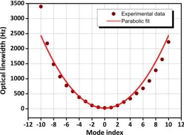
Fig. 4. Optical linewidth of the phase-compensated lines, ex-tracted from white FM noise PSD at 100 kHz, as a function of the mode index.
The linewidth dependence on mode index shows a parabolic profile indicating that residual jitter remains after active mode-locking. The optical linewidth of nthmode is determined by the following equation [10,12]:
δνn=δνmin+∆νRF(n−nmin)2 (8) Where δνminis the minimum intrinsic optical linewidth corre-sponding to the mode nmin,∆νRFis the full width at half max-imum of the MLLD fundamental RF beat note. Thanks to an appropriate parabolic fit, the latter has been estimated to be 24 Hz for the phase-compensated output comb. This might be attributed to the RF synthesizer phase noise.
In summary, we show that the limitations to the noise reduc-tion are twofold : (i) at frequencies below 10 kHz, the limit is
An efficient and simultaneous reduction also has been reported, demonstrating an OFC source with 14 comb-lines reduced to sub-kHz intrinsic linewidth. To the best of our knowledge, this is the first time that such performances, on linewidth reduction, are obtained using a feed-forward architecture. Those perfor-mances might be improved at low frequencies by the use of a frequency-stabilized local oscillator.
REFERENCES
1. J. Ye and S. T. Cundiff, Femtosecond optical frequency comb: principle, operation and applications (Springer Science & Business Media, 2005). 2. J. Lee, K. Lee, Y.-S. Jang, H. Jang, S. Han, S.-H. Lee, K.-I. Kang, C.-W.
Lim, Y.-J. Kim, and S.-W. Kim, Scientific reports4 (2014).
3. P. J. Delfyett, S. Gee, M.-T. Choi, H. Izadpanah, W. Lee, S. Ozharar, F. Quinlan, and T. Yilmaz, Journal of Lightwave Technology24, 2701
(2006).
4. P. Anandarajah, R. Maher, Y. Xu, S. Latkowski, J. O’Carroll, S. Murdoch, R. Phelan, J. O’Gorman, and L. Barry, IEEE Photonics Journal3, 112
(2011).
5. J. Pfeifle, V. Brasch, M. Lauermann, Y. Yu, D. Wegner, T. Herr, K. Hartinger, P. Schindler, J. Li, D. Hillerkuss, R. Schmogrow, C. Weimann, R. Holzwarth, W. Freude, J. Leuthold, T. J. Kippenberg, and C. Koos, Nature photonics8, 375 (2014).
6. T. Healy, F. C. G. Gunning, A. D. Ellis, and J. D. Bull, Optics express15,
2981 (2007).
7. B. W. Tilma, M. Mangold, C. A. Zaugg, S. M. Link, D. Waldburger, A. Klenner, A. S. Mayer, E. Gini, M. Golling, and U. Keller, Light: Science & Applications4, e310 (2015).
8. L. A. Jiang, M. E. Grein, H. A. Haus, and E. P. Ippen, IEEE Journal of Selected Topics in Quantum Electronics7, 159 (2001).
9. R. Paschotta, Applied Physics B: Lasers and Optics79, 163 (2004).
10. F. X. Kärtner, U. Morgner, T. Schibli, R. Ell, H. A. Haus, J. G. Fujimoto, and E. P. Ippen, Topics in Applied Physics95, 73 (2004).
11. Y. Takushima, H. Sotobayashi, M. E. Grein, E. P. Ippen, and H. A. Haus, in “Optics East,” (International Society for Optics and Photonics, 2004), pp. 213–227.
12. R. Rosales, K. Merghem, A. Martinez, F. Lelarge, A. Accard, and A. Ramdane, Optics express20, 9151 (2012).
13. W. Freude, J. Pfeifle, R. Watts, I. Shkarban, S. Wolf, V. Vujicic, P. Landais, N. Chimot, S. Joshi, K. Merghem, C. Calò, M. Weber, A. Ram-dane, F. Lelarge, L. Barry, and C. Koos, in “17th International Conference on Transparent Optical Networks (ICTON),” (IEEE, 2015), pp. 1–4. 14. A. Kakkar, N. J. Rodrigo, R. Schatz, X. Pang, O. Ozolins, A. Udalcovs,
H. Louchet, S. Popov, and G. Jacobsen, Scientific reports7, 844 (2017).
15. R. T. Watts, S. G. Murdoch, and L. P. Barry, IEEE Photonics Journal8,
1 (2016).
16. G. Girault, L. Le Gay, S. Lobo, L. Bramerie, M. Joindot, J.-C. Simon, A. Shen, F. Blache, H. Gariah, F. Mallécot, O. Le Gouezigou, F. Poingt, L. Le Gouezigou, F. Pommereau, B. Rousseau, F. Lelarge, and G.-H. Duan, Electronics Letters44, 873 (2008).
17. V. Panapakkam, A. P. Anthur, V. Vujicic, R. Zhou, Q. Gaimard, K. Merghem, G. Aubin, F. Lelarge, E. A. Viktorov, L. P. Barry, and A. Ramdane, IEEE Journal of Quantum Electronics52, 1 (2016).
18. OEwaves, “Ultra-Narrow Linewidth Laser Module-Gen 3,”http://www. oewaves.com/narrow-linewidth-laser/unllm-gen-3.
19. S. Camatel and V. Ferrero, Journal of Lightwave Technology26, 3048
(2008).
20. G. Stéphan, T. Tam, S. Blin, P. Besnard, and M. Têtu, Physical Review A71, 043809 (2005).
21. T. N. Huynh, S. P. Ó. Dúill, L. Nguyen, L. A. Rusch, and L. P. Barry, Applied optics53, 830 (2014).