ACOUSTIC PERFORMANCE ANALYSIS OF AN APPARENT CLT FLOOR STRUCTURE
BY CHENG QIAN
MANUSCRIPT-BASED THESIS PRESENTED TO THE UNIVERSITY OF QUEBEC AT CHICOUTIMI IN PARTIAL FULFILLMENT OF THE REQUIREMENTS FOR THE DOCTOR OF
PHILOSOPHY IN ENGINEERING
Supervisor: Sylvain Ménard ing., Ph.D.
Professor at the University of Québec at Chicoutimi
Co-supervisors: Delphine Bard Ph.D., Docent Associate Professor at Lund University Jean-Luc Kouyoumji Ph.D. Research Project Manager at FCBA
Québec, Canada
I
RÉSUMÉ
Avec le développement des sciences du bois et des techniques de construction, de plus en plus de bâtiments de grandes hauteurs, de longues portées se retrouvent dans le marché. Au cours des dernières années, la part de marché de la construction en bois n'a cessé d'augmenter. Contrairement à la renaissance de la construction en bois, le problème de l'isolation acoustique interpelle l'industrie. En général, par rapport à la construction lourde conventionnelle, comme les bâtiments en béton, les constructions en bois sont vulnérables au bruit, en particulier au bruit d'impact en basse fréquence. Différentes normes sont appliquées aux bâtiments en bois pour évaluer leurs performances acoustiques. Cependant, la norme ISO ne prend pas la considération le bruit en basse fréquence (en-dessous de 100 Hz). En conséquence, les occupants des bâtiments en bois peuvent se plaindre du bruit provenant de leurs voisins même si ces bâtiments respectent toutes les exigences de la réglementation. En revanche, en raison des différentes techniques de construction et de la grande variation des propriétés des matériaux à la base de bois, une haute qualité d'isolation acoustique devient difficile à atteindre par rapport aux constructions lourdes.
Les recherches réalisées dans cette thèse visent à acquérir une connaissance du comportement vibro-acoustique d’un plancher Cross Laminated Timber-béton et à développer un modèle de prédiction des bruits d'impact à basse fréquence de ce plancher. Pour atteindre ces objectives, les recherches ont été conduites en trois étapes principales: la prediction de la force; la description des incertitudes introduites par les propriétés mécaniques du bois; la modélisation du comportement dynamique d’un plancher bois-béton. Dans un premier temps,
II la force générée par la machine à choc ISO a été modélisée d’une manière indirecte. Au lieu de décrire directement la force générée par la machine à choc, la force est déduite à partir des accélérations du plancher et de la réponse fréquentielle du plancher. Ensuite, des tests expérimentaux ont été effectués pour extraire les informations dynamiques du plancher en bois et du plancher bois-béton. Par la suite, une approche stochastique a été proposée pour quantifier les incertitudes induites par les propriétés des matériaux du bois et pour automatiser la procédure de calibration. Basé sur le modèle du Cross Laminated Timber établi, différents matériaux ont été ajoutés au modèle pour simuler la réponse dynamique du plancher flottant. Une première investigation sur la force générée par cinq marteaux a été réalisée. Le niveau de pression acoustique rayonné par le plancher flottant a été simulée en intégrant la méthode de modélisation de la force et le modèle de plancher flottant. À partir des résultats de la simulation, il a été constaté que les propriétés du matériau ont un impact significatif sur les simulations dynamiques. Les propriétés plus précises du matériau peuvent conduire à un résultat plus précis.
Pour résumer, la connaissance sur la réponse dynamique du plancher a été obtenue par ce projet. De plus, des différentes méthodes pour modéliser le comportement dynamique du plancher sont appliquées afin d’obtenir des résultats précis. La connaissance apportée par cette recherche est un pas vers un modèle fiable de prédiction du bruit d'impact en basse fréquence.
III
ABSTRACT
Recent developments and innovations in wood science and manufacturing techniques, as well as environmental considerations, have contributed to the expansion of wooden constructions in the market. However, despite promising developments during the last decades, further expansion of the market share of wooden construction has been thwarted by problems at the level of acoustic insulation. Indeed, when compared to more conventional concrete constructions, the new wooden constructions are reputed to be vulnerable to noise; especially impact noise in the low-frequency range. One of the difficulties with the current standards used for the evaluation of the acoustic performance of wooden buildings is that these standards were originally developed for concrete buildings. Unfortunately, these standards do not include the most annoying low-frequency noises to which wooden structures are particularly vulnerable. As a result, even though these buildings conform to current building standards, the inhabitants in these dwellings complain about the noise coming from their neighbors. On the other hand, because of the different building techniques used, and the broad material properties of wood itself it can be difficult to achieve a high quality of acoustic insulation in wooden structures, especially when compared to concrete constructions.
The research reported in this thesis aims at developing a low-frequency impact sound prediction model for this type of floor. Three research steps were needed to achieve this: first, the prediction of the force; second, the quantification of the uncertainties induced by the material properties of wood; third, the modelling of the dynamic behavior of actual samples of
IV Cross Laminated Timber-concrete flooring. In the first step, the force generated by the ISO tapping machine was modelled by means of an indirect method that derived the force by the accelerations of the floor and the dynamic response of the floor instead of directly describing the force. Then, the tests were conducted to extract the dynamic information of the Cross Laminated Timber bare floor as well as the Cross Laminated Timber-concrete floor. The obtained experimental data are served as a reference to calibrate the model afterward. A stochastic approach was proposed to quantify the uncertainties induced by the material properties of wood and to automize the calibration procedure. Based on the developed Cross Laminated Timber model, different materials were integrated to the model to simulate the dynamic response of the floating floor. An initial investigation of the force generated by five hammers was carried out. The pressure radiated by the floating floor was simulated by integrating the force modelling method and the floating floor model. From the experimental phase, it can be concluded that the dynamic response of the structure is sensitive to the boundary conditions. In future experiment trials in order to successfully extract the useful dynamic information of the structure, the boundary conditions should be well defined. For the simulation perspective, it was found that the accuracy of the floor model can have an impact on the accuracy of the simulation of the force. Accurate material properties are one crucial prerequisite to have a more accurate floor model. From the simulation results, it can be seen that the material properties have a significant impact on the dynamic simulations. The use of more accurate material properties can lead to a more accurate result.
V To sum up, knowledge of the dynamic behavior of the floors is obtained through this project and different modelling methods were applied in order to provide a relatively accurate simulation result. This research has successfully moved us one step towards a reliable low-frequency range impact sound prediction model.
VI
ACKNOWLEDGMENT
First, I would like to thank my supervisor, Dr. Sylvain Ménard, for giving me the opportunity to come to Canada for this Ph.D. project and for his continuous support and encouragement. Likewise, I am grateful to co-supervisor Dr. Delphine Bard for keeping my stay at Lund University and also for the nice discussions and guidance. Then, I want to extend my thanks to my co-supervisor Dr. Jean-Luc Kouyoumji for the guidance of the experimental tests.
I am grateful to CIRCERB and CRMR and the industrial partners, FPInnovations and Nordic Chantier Chibougamau. A very special thanks goes to Julie Frappier and William Munoz and the fellows of their group to provide the CLT panels so that the tests on CLT can finally be done. Thanks Mr. Sylvain Gagnon for providing their laboratory for the tests and thanks Mr. Anes Omeranovic for mounting the specimens so that the tests could be carried out. I want to express my deep gratitude to Dr. Lin J Hu. She always gives me the insightful suggestions and encourages me at the most difficult moment during this research. Dr. Jian H Zhou is acknowledged for his suggestions which inspired me to go further in the research. A word for thanks to my co-author Dr. Juan Negreira for his generous help and the reviews in particular. I am also pleased to extend my greetings to the colleges from the University of Québec at Chicoutimi and Lund University. Thanks to all the professors at Lund who have given me useful suggestions.
Jie Zhang and Jing Li, thank you for your company during my stay in Sweden and also for telling me how to face challenges in life. Without you, the journey would not have been as pleasant.
VII A special thanks to my uncle, Rong W Qian, for his support. He is always reachable whenever I need a talk. Finally, I would like to thank my parents for their love, support, and understanding throughout my life.
VIII
Table of Contents
RÉSUMÉ ... I ABSTRACT ... III ACKNOWLEDGMENT ... VI PUBLICATIONS ... XI Peer-reviewed Journal Articles ... XI Conference Articles and Presentation ... XI LIST OF TABLES ... XIII LIST OF FIGURES ... XIV LIST OF ABBREVIATIONS ... XVI LIST OF SYMBOLS ... XVIICHAPTER 1 GENERAL INTRODUCTION ... 1
1.1. Introduction... 1
1.2. Problem Statement ... 3
1.3. Objectives ... 5
1.4. Originality of the Research ... 6
1.5. Methodology ... 7
1.6. Thesis Organization and Relationships between the Different Chapters ... 9
CHAPTER 2 LITERATURE REVIEW ... 11
2.1. Sound Insulation in Wooden Buildings ... 11
2.1.1. Airborne Sound ... 12
2.1.2. Impact Sound ... 13
2.2. Wood as a Construction Material ... 15
2.2.1. Mechanical Properties of Wood ... 15
2.2.2. Cross-Laminated Timber ... 19
2.3. Modelling Approaches and Measurement Method ... 25
2.3.1. Modelling Approaches ... 25
2.3.2. Measurement Method ... 28
2.3.3. Force Generated by ISO Tapping Machine ... 32
2.3.4. Stochastic Approach ... 35
2.3.5. Floating Floor Modeling ... 36
CHAPTER 3 MODELLING OF THE DYNAMIC BEHAVIOR OF THE ISO TAPPING MACHINE ... 38
IX
Abstract ... 40
3.1. Introduction... 41
3.1.1. Aims and Outline of the Chapter ... 42
3.2. Experimental Tests on the CLT Floor ... 43
3.2.1. Specimen Description ... 43
3.2.2. Measurement Set-up ... 43
3.2.3. Experimental Modal Analysis Test on the CLT Floor ... 44
3.3. Dynamic Behavior of CLT Floor Modelling ... 46
3.3.1. Error Metrics ... 47
3.3.2. Model Description ... 48
3.3.3. Model Calibration ... 49
3.3.4. Results and Discussions ... 51
3.4. Dynamic Behavior of the ISO Tapping Machine Modelling ... 52
3.4.1. Force Determination ... 53
3.4.2. Results and Discussions ... 54
3.5. Conclusions... 55
CHAPTER 4 STOCHASTIC CALIBRATION PROCEDURE ... 57
Résumé... 58
Abstract ... 59
4.1. Introduction... 60
4.1.1. Aims and Outline of the Chapter ... 61
4.2. Preliminary Sensitivity Analysis ... 62
4.3. Preliminary Single Variable Investigation ... 66
4.4. Stochastic Process ... 68
4.4.1. Decomposition of the Random Elastic Tensor ... 70
4.4.2. Construction of Probability Distribution Function in High-Dimension Using the Maximum Entropy Principle ... 72
4.4.3. Numerical Application of the Orthotropic Symmetric Material (CLT) ... 78
4.4.4. Sampling the Defined Probability Distribution Function by Metropolis-Hastings Algorithm ... 82
4.5. Implementation of Stochastic Data in Abaqus... 83
4.6. Results and Discussions ... 85
X
4.6.2. Calibration of the CLT Panel ... 87
4.7. Conclusions... 96
CHAPTER 5 MODELLING OF THE CONCRETE-CLT FLOOR ... 99
Résumé... 100
Abstract ... 101
5.1. Introduction... 102
5.1.1. Aims and Outline of the Chapter ... 104
5.2. EMA on the Concrete-CLT Floating Floor ... 105
5.3. FE Model Development of Concrete-CLT Floating Floor ... 109
5.3.1. Model description ... 110
5.3.2. Model calibration ... 113
5.4. Results and Discussions ... 121
5.5. Conclusions... 123
5.6. Additional Content not Presented in the Original Paper ... 123
5.6.1. ISO Tapping Machine Model Development ... 124
5.6.2. Sound Radiation Calculation and Impact Sound Improvement Investigation ... 126
CHAPTER 6 CONCLUSIONS AND RECOMMENDATIONS ... 130
6.1. Conclusions... 130 6.2. Recommendations ... 132 REFERENCES ... 134 ANNEXES ... 142 Python Code ... 142 Matlab Code ... 148
XI
PUBLICATIONS
Peer-reviewed Journal Articles
1. Qian, C., Ménard, S., Bard-Hagberg, D., Kouyoumji, J. L., & Negreira, J. (2019). Calibration of the ISO tapping machine for finite-element prediction tool on a wooden-base floor. Building
Acoustics. https://doi.org/10.1177/1351010X19855227. Impact factor: 0.77
2. Qian, C., Ménard, S., Bard, D., & Negreira, J. (2019). Development of a vibroacoustic stochastic finite element prediction tool for a CLT floor. Applied Sciences (Switzerland), 9(6), [1106]. https://doi.org/10.3390/app9061106. Impact factor: 1.06
3. Qian, C., Ménard, S., Bard-Hagberg, D., Kouyoumji, J. L., & Negreira, J. Development of a numerical model for predicting low-frequency dynamic behavior of a floating timber-concrete floor. To be submitted.
Conference Articles and Presentation
1. Qian, C., Ménard, S., Bard, D., & Negreira, J. (2018). Description and calibration of the ISO tapping machine in numerical impact sound predictive tools. In 47th International Congress
XII 2. Qian, C., Ménard, S., Bard, D., & Negreira, J. (2019). Development of stochastic finite prediction element model for CLT floors. In 26th International Congress on Sound and
Vibration (ICSV 2019).
3. Qian, C., (2019). Development of a numerical prediction model for impact sound insulation performance in wooden buildings. Woodrise 2019.
XIII
LIST OF TABLES
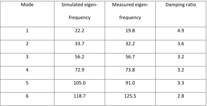
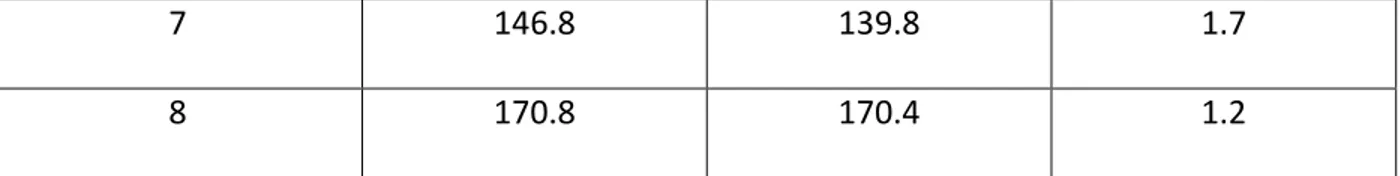
Table 3.1: Material properties of CLT used in the calibrated FE model. ... 49 Table 3.2: Simulated and measured eigen-frequencies of the bending modes and the
corresponding measured damping ratios. ... 49 Table 4.1: Material properties of CLT collected from the literature. ... 63 Table 4.2: Material Properties of CLT used in the calibrated FE model. ... 92 Table 4.3: Measured and simulated eigen-frequencies of the bending modes and the measured corresponding damping ratios. ... 92 Table 5.1: Measured eigen-frequencies of the bending modes and the measured corresponding damping ratios. ... 108 Table 5.2: Material properties of gypsum board and acoustic impact board collected from the literature. ... 112 Table 5.3: Calibrated material properties of the gypsum board and acoustic impact board. ... 118
XIV
LIST OF FIGURES
Figure 1.1: (a) Condos Origine, Québec City, Canada. (b) 18-storey timber Brock Commons
tower, Vancouver, Canada. (Source: Woodskyscrapers) ... 2
Figure 1.2: Impact sound transmission. “D” denotes direct transmission whereas “Fi” indicates the different flanking paths involved [12]. ... 4
Figure 1.3: Structure of the research. ... 8
Figure 2.1: Airborne sound transmission. “D” denotes direct transmission whereas “Fi” indicates the different flanking paths involved [12]. ... 12
Figure 2.2: Structural acoustic process [40]. ... 13
Figure 2.3: (a) Cross-section of a raw wood log; (b) Rectangular orthotropic wood model [14]. 17 Figure 2.4: CLT panel configuration [59]. ... 20
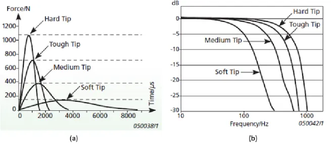
Figure 2.5: (a) Impulse shapes of the hammers showing the shape as a function of the used impact tip. (b) Force spectra of the hammers showing the frequency response as a function of used impact tip [90]. ... 31
Figure 2.6: Illustration of the EMA set-up. ... 31
Figure 2.7: ISO standardized tapping machine [14]. ... 33
Figure 2.8: (a) Time dependence of force produced by the mechanical hammer system (b) Spectrum of force [96]. ... 34
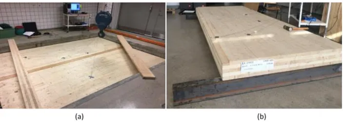
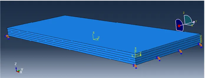
Figure 3.1: (a) Two leaves CLT panel connected with a thin lath in the standardized step sound laboratory; (b) Simply supported CLT panel. ... 44
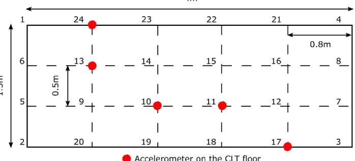
Figure 3.2: Mesh drawn on the surface of the CLT floor. ... 45
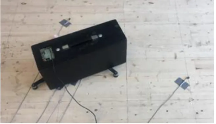
Figure 3.3: Measurement of the tapping machine on the top of the floor. ... 46
Figure 3.4: FE model of the 5-ply CLT. ... 48
Figure 3.5: NRFDs of the simulated and measured eigen-frequencies. ... 50
Figure 3.6: MAC of the simulated and measured mode shapes of the CLT floor... 51
Figure 3.7: FRFs of points 11, 13, 17 and 24. The measurement results are shown in blue and the simulation results in red. ... 51
Figure 3.8: (a) Acceleration of CLT at point 10 in narrowband; (b) Acceleration of CLT at point 10 in 1/3 octave band. Measured acceleration in blue and simulated acceleration in red. ... 54
Figure 4.1: NRFDs of Young’s moduli. ... 64
Figure 4.2: NRFDs of shear moduli. ... 64
Figure 4.3: NRFDs of Poisson's ratios. ... 65
Figure 4.4: FRFs of the point 13 and 24. The blue curves are the measurement results, and the red curves (40 realizations) are the simulation results with different material properties. ... 67
Figure 4.5: Flow chart of the application of the stochastic process. ... 70
Figure 4.6: Convergence of the optimization algorithm. ... 82
Figure 4.7: (a) Joint probability density function of random variables C11 and C22. (b) Joint probability density function of random variables C22 and C33. ... 83
Figure 4.8: Measured (blue) and simulated (red) FRFs at points 11, 13, 17, and 24. ... 86
Figure 4.9: (a) Air gaps in the laminate layers of CLT. (b) No edge-bonding of CLT. ... 87
XV
Figure 4.11: Measured and simulated modes. ... 91
Figure 4.12: Cross-MAC. ... 91
Figure 4.13: Magnitude of the complex mobility in the vertical direction of points 11, 13, 17, and 24. Simulated FRFs in red, measured FRFs in blue. ... 94
Figure 5.1: Two types of floating floor: (a) Floating floor with the continuous elastic interlayer; (b) Floating floor with a discontinuous elastic interlayer. ... 103
Figure 5.2: Compositions of the floating floor. Materials from the top to the bottom: concrete; insulation layers; gypsum boards; CLT panel. ... 103
Figure 5.3: Accelerometer positions in the EMA test on the floating floor. ... 106
Figure 5.4: (a) Gypsum board on the top of the CLT floor; (b) Resilient layer and gypsum board on the top of the CLT floor. ... 107
Figure 5.5: FRF at point 11 of the gypsum board-CLT floor. ... 107
Figure 5.6: FE model with different materials and the connections: (1) Concrete-acoustic insulation layer connection; (2) Gypsum board-acoustic insulation layer connection; (3) CLT-gypsum board connection. ... 112
Figure 5.7: Sensitivity analysis of the FE model. ... 114
Figure 5.8: 12th measured mode and 12th simulated mode. ... 116
Figure 5.9: Measured modal damping ratios and fitted Rayleigh damping. ... 117
Figure 5.10: NRFD calculated based on the experimental data of the concrete floor. ... 118
Figure 5.11: MAC calculated based on the experimental data of the concrete floor. ... 119
Figure 5.12: FRFs at different excitation and receiving points on the concrete floor which describe horizontal mobility. The first subscript of the FRF title indicates the excitation point and the second one refers to the receiving point. The simulation curves are in red and the measured curves are in blue. ... 120
Figure 5.13: FRFs at different excitation and receiving points under the CLT floor which describe the vertical mobility. The first subscript of the FRF title indicates the excitation point and the second one refers to the receiving point. The simulation curves are in red and the measured curves are in blue. ... 121
Figure 5.14: Accelerations at the different measurement points. In figure (a), the accelerations generated by one hammer; in figure (b), (c) and (d), the simulation results are shown in red and the experimental results are shown in blue. ... 125
Figure 5.15: SPL generated by the floating floor is in blue dotted line and SPL generated by the CLT bare floor is in red dotted line. The sound pressure level improvement of the floating floor is the black solid line. The frequency band is in the 1/3 Octave band. ... 128
XVI
LIST OF ABBREVIATIONS
CLT Cross-Laminated Timber NLT Nailed-Laminated Timber EWP Engineered Wood Product EMA Experimental Modal Analysis FEM Finite Element Method
SEA Statistical Energy Analysis FRF Frequency Response Function
NRFD Normalized Relative Frequency Difference MAC Modal Assurance Criterion
PDF Probability Distribution Function ISDE Itô Stochastic Differential Equation MHA Metropolis-Hastings Algorithm
XVII
LIST OF SYMBOLS
𝜎𝑖,𝑗 Stress [Pa] 𝜀𝑖,𝑗 Strain
𝐸𝑖𝑗 Young’s modulus [Pa] 𝐺𝑖𝑗 Shear modulus [Pa] 𝜈𝑖𝑗 Poisson’s ratio
𝐹𝑛 Fourier coefficient
𝜔𝑛 Angular frequency [rad/s] 𝐼 Momentum [kg m/s]
𝑣0 Initial velocity that the hammer strikes the floor [m/s] 𝑓0 Resonance frequency of the floating floor [Hz]
𝑠 Dynamic stiffness per unit area of the resilient layer [Pa]
𝜌𝑖
Mass per unit area of the upper and structural slabs [kg/m3]
𝑓𝑠𝑖𝑚 Simulated eigen-frequency [Hz] 𝑓𝑚𝑒𝑠 Measured eigen-frequency [Hz] Φ𝑖𝑠𝑖𝑚 Simulated eigen-vector
Φ𝑗𝑚𝑒𝑠 Measured eigen-vector
𝐴𝑖 Accelerations of the floor at point 𝑖 [m/s2]
XVIII 𝐹𝑖 Force generated by impact hammer at point 𝑖
𝑐𝑖
Set of random coefficients that can be described by its PDFs
𝑪 Random elastic tensor
𝑬𝒊 Tensor basis of the random elastic tensor 𝑪 𝒂, 𝒃, and 𝒄 Unit orthogonal vectors
⊗ Kronecker product
𝑃𝒄(𝑑𝒄) unknown probability distribution
𝑆(𝑝) Entropy
𝜆𝑖 Lagrange multipliers 𝒈(𝒄) Mapping of 𝒄
Φ(𝒖, 𝝀) Potential function
𝑼(𝑟), 𝑽(𝑟) Markov stochastic process 𝛩, 𝛵, 𝛲 Probability space
𝑾(𝑟) Normalized Wiener process 𝑩𝜆 Random variable
𝑟𝑜 Iteration step
𝑓𝑡𝑎𝑟𝑔𝑒𝑡 Target vector
𝑝(𝑓) Pressure radiated by a point 𝜌0 Air density [kg/m3]
𝑞0 Volume velocity [m3/s]
XIX 𝑟
Distance between the point source and the receiving point [m]
1
CHAPTER 1 GENERAL INTRODUCTION
1.1. Introduction
The market share of timber constructions for industrial and residential multi-storey buildings has been rapidly increasing during the last decades [1]. Recent research points out that wooden construction innovations can reduce carbon dioxide emissions and fossil fuel consumption [2-7]. This renewable material consumes relatively low energy to be produced and has fewer side effects on the environment, such as water pollution and green gas emission. Light in weight, high degree of prefabrication, fast transportation, low storage costs, and easy to assembly, all these outstanding advantages lead to a steady increase of wooden constructions in market share [8]. Moreover, wooden construction is a great interest in Canada due to its abundant wood resource. The Canadian forest industry contributes billions of dollars each year and no nation derives a more net benefit from trade in forest products than Canada [9].
Today, massive timber panels, such as Cross-Laminated Timber (CLT), Nailed-Laminated Timber (NLT), etc. become the popular alternative of concrete in mid- and high-rise constructions due to their optimized properties which meet the specific needs of the structural design. Massive timber panels can be used as load-carry elements, such as walls and floors in constructions because of their high strength and dimensional stability [10]. Among all massive timber panels, CLT is one of the most popular massive timber panels due to its low air permeability and distinctive specific storage capacity for humidity and thermal energy. Low mass allows CLT to construct on the soil with weak load-bearing properties. It is suitable for the upgrading of existing
2 buildings [11]. CLT continuously breaks the limits of high-rise timber buildings, such as Condos Origine and Brock Commons, shown in Figure 1.1.
Figure 1.1: (a) Condos Origine, Québec City, Canada. (b) 18-storey timber Brock Commons tower, Vancouver, Canada. (Source: Woodskyscrapers)
However, acoustic insulation is a challenge for multi-storey wooden buildings, especially low-frequency noise. Complaints about the noise coming from neighbors, traffic, installation, etc. are raising from the inhabitants in these wooden buildings, even these wooden dwellings have already fulfilled the current acoustic insulation standards. According to the ISO standards, the frequency range of the impact sound measurement standards begins from 100 Hz and up to 3150 Hz [12, 13]. Like Sweden, the frequency range of evaluation can be decreased to 50 Hz. However, the first several eigen-frequencies of floors which cause the most significant annoyance, like foot-fall noise, are lower than 50 Hz [14]. But these frequencies are excluded from the evaluation procedures. As a consequence, even though the wooden constructions fulfilled the requirements of standards, the low-frequency issue isn’t really addressed, resulting in many complaints coming from the residents [15].
3 To address this problem, it is always desirable to know the acoustic insulation performance of the structure element before the construction in order to prevent the costly changes after the erection of the building. Today most prediction approaches are based on empirical engineering experiences and tests. But in general, the tests could be expensive and time-consuming. The results given by the tests in the laboratory do not always correlate with in-situ measurements. In the laboratory, the flanking transmissions are removed, whereas, in-in-situ, the flanking transmission can play an important role in sound insulation, which can result in a degraded sound insulation performance. Prediction models, in spite of being highly useful for the design of new buildings, are still very lacking today [14]. Gaining an adequate understanding of the dynamic behavior of wooden construction would be one important step towards a reliable prediction model. In this report, the dynamic behavior of the bare CLT floor and the CLT-concrete floor were investigated. The corresponding models were established based on the experimental results to simulate the dynamic behavior of the floors.
1.2. Problem Statement
From the practice, it is proven that dynamic behavior of floor, especially the impact sound at low frequencies, like foot-fall noise [16-19], is an important consideration in the design phase and neglecting the dynamic behavior of floor will degrade the acoustic insulation for occupants, especially for who lives in the wooden buildings. The impact sound transmission is illustrated in Figure 1.2. A well-known example [20] in North American is that one supposed to be a “luxury” condos in the San Francisco Bay Area received an $80 million class-action suit against the developer. One of the major claims is the footfall noise coming from the wooden ceiling. From
4 this example, we can see that more attention should be paid to the low-frequency noise in wooden construction.
Figure 1.2: Impact sound transmission. “D” denotes direct transmission whereas “Fi” indicates the different flanking paths involved [12].
In recent years, many research found that lightweight buildings do not behave like heavy constructions [21-30]. Lightweight buildings perform better acoustic insulation in mid- and high-frequency range comparing to heavy constructions, whereas, the low-high-frequency acoustic insulation performance should be further investigated [31]. But current standards, such as ISO 10140 and ISO 717, do not evaluate the sound insulation below 100 Hz (optionally below 50 Hz). In the recent research[32], it was found that the correlation determination between 𝐿′𝑛,𝑤+ 𝐶𝐼,50−2500 and the subjective evaluation is only 32%, whereas, when the frequency band of 𝐿′𝑛,𝑤+ 𝐶𝐼,20−2500 is extended to 20 Hz, the corresponding correlation is remarkably increased (up to 74%). Furthermore, from the perspective of the FEM modelling, the lack of reliable input
5 parameters of the material and different construction techniques make the high sound insulation quality of the wooden buildings more difficult to be attained [33]. Wood being a natural material has more uncertainties comparing to a homogenous artificial material. So far, there is no accurate calculation method for the acoustic performance of lightweight buildings [6, 14, 34]. The product development is mainly based on the empirical experience [35]. In order to improve the impact sound insulation of wooden buildings, it is desirable to know more knowledge of low-frequency vibro-acoustic behavior of wooden buildings. And reliable prediction tools are in need to prevent expensive over-designed acoustic solutions before the constructions.
1.3. Objectives
The main objective of this project is to try to gain the knowledge of the vibro-acoustic behavior of the cross laminated timber-concrete floor and to develop a low-frequency impact sound prediction model for this type of floor. The prediction of an acoustic pressure field can be divided into three steps: 1) Predicting the force caused by the impact source; 2) Predicting the transmission of vibrations from the location of the impact to the receiving room; 3) Predicting the acoustic pressure field caused by the vibrations in the ceiling, walls, and floor of the receiving room [36]. The research scope of this thesis focusses on the prediction of the impact source and the transmission of vibrations. The prediction of the sound pressure emitted by the structure is roughly investigated under certain strict assumptions. To achieve that, the force generated by the ISO tapping machine should be characterized. After that, the dynamic response of the CLT bare floor and the CLT-concrete floor should be investigated in order to predict the impact sound afterward.
6 So, derived from the main objective, several specific objectives are presented in the following points:
1) Proposing a modeling method to characterize the force introduced by the ISO standardized tapping machine.
2) Gaining knowledge of the dynamic properties of the CLT bare floor and CLT-concrete floor. 3) Developing a modeling method to automate the orthotropic material calibration
procedure and to quantify the uncertainties induced by the material properties.
4) Investigating the modeling method of the connections between different materials of the CLT-concrete floor and developing a FE model to make a step towards predicting vibro-acoustic behavior of the CLT-concrete floor.
1.4. Originality of the Research
Acoustic insulation is one of the main challenges of wooden dwellings, especially the low-frequency impact noise. This is due to the fact that wooden constructions respond more actively to a given input excitation comparing with heavy constructions [6]. Moreover, the various construction methods and the big variations of the material properties of wood make the acoustic performance of the wooden buildings more difficult to predict. Consequently, in some multi-storey wooden buildings, many residents perceive the impact sound as annoying noise even though these buildings have fulfilled the requirements of the regulations [25, 37-39]. Today, due to the lack of reliable input material properties of structures and knowledge of the wooden buildings, no reliable prediction model is available to estimate the acoustic performance of wooden buildings before the construction. The purpose of this research is to establish a
7 prediction model of the floor. The vibro-acoustic behavior of the CLT bare floor and the CLT-concrete floor were obtained by means of experimental tests. Based on the dynamic response of the floors, the corresponding models were established. Modeling methods were developed to derive the force generated by the ISO tapping machine, to characterize the uncertainties induced by the material properties of CLT and to describe the connections of different layers of the floating floor in the FE model. By integrating all the developed models, the dynamic response of the floor can be modeled, and subsequently, the accelerations can be calculated. The pressure radiated by the floor can be potentially determined under certain assumptions since the pressure is proportional to the accelerations of the floor [40]. The frequency band of the measurements as well as the corresponding models was enlarged up to 200 Hz. Furthermore, through the difficulties met in the measurement phase, the appropriate simplification of the boundary condition was proposed. And the adequate boundary condition modelling was found. All in all, this research is one step towards a reliable and accurate low-frequency impact sound prediction model.
1.5. Methodology
To achieve the goals of this project, the research was carried out through three steps, as shown in Figure 1.3. We begin with force characterization. The force generated by the tapping machine is described by means of the acceleration and dynamic response of the floor. Then, the CLT is calibrated by using the stochastic approach. Based on the methods developed, the dynamic behavior of the CLT-concrete floor is modelled.
8 Figure 1.3: Structure of the research.
To establish an impact sound prediction model, the force generated by the ISO tapping machine should be characterized. The dynamic properties (eigen-frequencies; eigen-modes; damping ratios) of the base floor (the CLT floor) were extracted from the experimental tests. The base floor model was established according to the measurement results. Then, the accelerations of the floor generated by ISO tapping machine were recorded in order to derive the input force yielded into the system. By integrating the force into the numerical model of the floor, the simulated accelerations were compared with the measured ones to validate the force modeling method. In order to facilitate the calibration procedure of the CLT floor and to quantify the uncertainties induced by the material properties of CLT, the stochastic model to describe the orthotropic material parameters was introduced into the model. The reference data to validate the model was the dynamic information of the floor obtained from the previous measurements.
9 The vibro-acoustic behavior of the CLT-concrete floor was studied in the final phase. The experimental tests were performed on this floating floor to obtain measurement data to validate the FE model afterward. The connections between different materials in the floating floor was studied. The material parameters of the materials on the floor were calibrated and validated by comparing the simulation results with the experimental data. An initial calculation of sound generated by the tapping machine and radiated by the floor was calculated under certain strict assumptions.
1.6. Thesis Organization and Relationships between the Different Chapters
This thesis consisting of six chapters is designed as a collection of the articles which cover the content of the work. To achieve the ultimate goal of this research, different studies were carried out. The 1st chapter dedicates to a general introduction of this thesis. The literature review is presented in the 2nd chapter. The 6th chapter is a general conclusion and the perspective for the future work.
To develop an impact sound prediction model, the first question is how to model the source of the impact sound. In the 3rd chapter, the force generated by the ISO tapping machine, which is employed as the impact source in the ISO standards, is studied. An indirect method of simulating the force is presented in the 3rd chapter.
During the development of force modeling, it was found that the model of the base floor where the ISO tapping machine was placed on can have an influence on the accuracy of the force
10 modeling. So, in the 4th chapter, a stochastic modeling approach was developed to quantify the uncertainties induced by the material properties of the structure and to automate the calibration procedure. The model validated was based on the experimental results.
The 5th chapter aims at investigating the modeling approach to characterize the dynamic behavior of the CLT-concrete floor. In the final section of this chapter, an initial try to calculate the pressure emitted by the floor was made by employing the modeling methods in the previous chapters.
11
CHAPTER 2 LITERATURE REVIEW
In this chapter, the context of the sound insulation in wooden buildings is given in the first section. A short introduction to wood as the construction material is presented. The modeling approaches, the statistical energy analysis (SEA) and the finite-element method (FEM) are briefly discussed. Following this, the literature review related to the research carried out in this project is presented in the last section.
2.1. Sound Insulation in Wooden Buildings
Acoustics includes sound and vibration [15]. Due to the variability and the intrinsic features of wood, wooden constructions are vulnerable to the sound insulation compared to the heavy constructions, like concrete buildings. Sound insulation in dwellings, generally, encompasses two different kinds: airborne sound insulation and impact sound insulation.
The current solutions to estimate the sound insulation performance of wooden buildings in the early design phase are based on either practical tests or employing the existing prediction methods. However, using the test to evaluate the acoustic performance of the constructions is not only expensive but also time-consuming. Meanwhile, the obtained results may not be useful just because of a slight change in construction. There exist some empirical models and prediction methods, like ISO 12354 [41-44], which estimates the airborne sound and impact sound performance by taking into account the flanking transmission. These standards are base on the Statistical Energy Analysis (SEA) which requires a diffuse vibration field. However, due to the higher internal loss of lightweight buildings, the reverberation vibration field is difficult to achieve,
12 especially in the low-frequency range, because of the lower modal density [45]. As a consequence, the uncertainties of the prediction increase in the low-frequency range [46]. Furthermore, the inhomogeneity and anisotropic of lightweight elements are not considered in the calculation standards [15] Therefore, reliable prediction tools are needed to avoid severe and costly changes in the design phase of wooden buildings.
2.1.1. Airborne Sound
Airborne sound can be described as sound waves generated by a sound source reaching a building structure, then causing vibration of structure which is transmitted to the other side of the structure and radiated out of the structure to create pressure variation in the air on the other side of the structure. Subsequently, the noise is created on the other side of the building element. The airborne sound transmission is described in Figure 2.1.
Figure 2.1: Airborne sound transmission. “D” denotes direct transmission whereas “Fi” indicates the different flanking paths involved [12].
Mass per unit area is an important factor for the airborne sound insulation in wooden construction. Because of the low density of the wood, wooden dwelling could be prone to
13 airborne sound issues, especially in the low-frequency ranges. Modern audio equipment, like HiFi system and appliances, are the typical airborne sound sources that can potentially generate annoying noise far below 100 Hz. Some Nordic countries have extended the frequency range of building code down to 50 Hz to dealt with the impact sound insulation issue. The airborne sound is out of the scope of this thesis and it will not be discussed in this work.
2.1.2. Impact Sound
The structural-acoustic process can be divided into four steps, shown in Figure 2.2. The first stage is the generation of oscillation. The second stage is the transmission which encompasses the transfer of oscillation energy from the mechanisms of generation to a structure. The third step is the distribution of energy throughout the oscillated structure system. This procedure is called propagation. The last one is radiation. Any structural part vibrating in the air passes on power to the air, and that is perceived as an audible sound [40].
Figure 2.2: Structural acoustic process [40].
Airborne sound and impact sound can be transmitted into the receiving room through the direct and flanking transmission. The waves generated on the top of the floors can propagate through the load-bearing walls and radiate into the receiving room, resulting in louder noise
14 compared to the noise only directly coming from the ceiling. The model development reported in this thesis is only one step towards an applicable prediction model. So, this work only focusses on the direct sound transmission, and the flanking transmission is beyond the scope of this thesis.
Impact sound has been reported as the most critical sound source in dwellings [47]. It is a long-standing problem needed to be tackled in the multi-family buildings, especially for wooden constructions [20, 48]. The low-frequency impact noise, typically generated by footfall or dropped object, is one of the most annoying impact sources in the wood-frame buildings [14, 15, 20, 25, 28, 32, 35, 48-53]. To dealt with that, different solutions are developed to decrease the impact sound transmission. These solutions are only capable of reducing impact noise in the mid- and high-frequency range; they fail to provide satisfactory performance in the low-frequency range [15].
Although the wooden dwellings are fulfilled the standard requirements, the complaints have still risen from the occupants in this type of buildings, especially the low-frequency noise. It was found that these standards do not function as they should be in wooden constructions since wooden buildings behave differently in low-frequency range other than concrete constructions. Furthermore, the ISO standards employ a tapping machine as the excitation source. The small hard masses of the tapping machine can hardly mimic the human walking without hard shoes, which can have no-linear effects. Moreover, the low-frequency impact sound evaluation is underestimated in the single number ratings defined in standards. This low-frequency issue could be partly resolved by introducing the low-frequency adaptation term. Recent research [25, 32]
15 reveals that there still exist mismatches between the subjective and the objective ratings, even with the adaptation terms. It was demonstrated that when the evaluation frequency range is enlarged down to 20 Hz, the correlations between the subjective ratings performed by inhabitants in wooden dwellings and the objective ratings performed by ISO standards can be largely improved. Because the first several eigen-frequencies of floor containing the most of vibration energy and believed to cause the most annoyance are lying under 30 Hz [54]. It is recommended that the impact sound evaluation should be extended to 20 Hz in order to achieve a higher acoustic quality of dwellings.
All in all, today’s standards are needed to be revised to provide more general and robust methods to facilitate acoustic comfort achievement in wooden buildings. Nevertheless, regarding the practical and juridical reasons, the wooden construction industry is still following the current standards even though the low-frequency sound evaluation, which is essential to achieve high acoustical quality in wooden dwellings, is excluded from the regulations. Thus, this thesis mainly focusses on gaining knowledge about the generation of the impact sound as well as the dynamic response of the excited wooden structures in the low-frequency range.
2.2. Wood as a Construction Material
2.2.1. Mechanical Properties of Wood
Wood has been used as a building construction material throughout history because of its unique mechanical and machining characteristics [10]. Wood is usually considered as a lightweight construction material since it has the high strength-to-weight ratio properties
16 compared to the conventional artificial construction materials, such as concrete or steel. With the same load-bearing capacity, wooden structures are lighter than concrete structures in general.
As a natural material, mechanical properties of wood are governed by the direction of fibers and the annual rings of the trees, meanwhile, they are also affected by the moisture contents and temperature [55]. Wood can be modeled in micro-scale, meso-scale as well as macro-scale levels depending on different purposes. Generally, wood is considered as homogenized cylindrical orthotropic structure, shown in Figure 2.3 (a), which is characterized by three mutually perpendicular axes, longitudinal (L), tangential (T) and radial (R). However, when the cross-section of the wooden structure is small or locates far from the pith of the trunk, the curve effect of the annual rings could be neglected [56]. For the sake of simplicity, wood can be described by the rectangular orthotropic model, shown in Figure 2.3 (b). The vibration of structures induced by human activities is very slight, and thereby wood can be modeled as a linear elastic and homogenous material at the macro-scale level in this thesis.
17
Figure 2.3: (a) Cross-section of a raw wood log; (b) Rectangular orthotropic wood model [14].
The constitutive behavior of the structure can be described by Hook’s law under the linear elastic assumption. The stress can be represented by nine stress components, 𝜎𝑖,𝑗, with 𝑖, 𝑗 = 1,2,3. Same as stress, the strain can also be represented by nine strain components, 𝜀𝑖,𝑗, with 𝑖, 𝑗 = 1,2,3. Regarding the symmetrical plans of the strain and stress in the three mutually perpendicular directions, the orthotropic materials can be expressed as:
{ 𝜀1 𝜀2 𝜀3 𝛾4 𝛾5 𝛾6} = [ 𝑆11 𝑆12 𝑆13 0 0 0 𝑆12 𝑆22 𝑆23 0 0 0 𝑆13 𝑆23 𝑆33 0 0 0 0 0 0 𝑆44 0 0 0 0 0 0 𝑆55 0 0 0 0 0 0 𝑆66]{ 𝜎1 𝜎2 𝜎3 𝜏4 𝜏5 𝜏6} (2-1)
In this work, the engineer constants are employed in the FE modeling software to model the wooden structure. For the sake of simplicity and modeling concerns, the Hook’s law of orthotropic material expressed with the help of the engineer constants is shown in Equation (2-2).
18 { 𝜀1 𝜀2 𝜀3 𝛾4 𝛾5 𝛾6} = [ 1 𝐸1 −𝜈21 𝐸2 −𝜈31 𝐸3 0 0 0 −𝜈12 𝐸1 1 𝐸1 − 𝜈32 𝐸3 0 0 0 −𝜈13 𝐸1 − 𝜈23 𝐸2 1 𝐸3 0 0 0 0 0 0 1 𝐺23 0 0 0 0 0 0 1 𝐺13 0 0 0 0 0 0 1 𝐺12] { 𝜎1 𝜎2 𝜎3 𝜏4 𝜏5 𝜏6} (2-2)
Wood as a natural material has imperfections, such as the knots or the growth ring irregularities. These natural defects create the variations of elastic constants not only in the different species of wood but also in the nominally identical wooden structures, as well as in single one log. Subsequently, they result in the different dynamic behavior of the wooden structures. As a consequence, the mechanical properties of wood (even with the same species of wood) are difficult to quantify and the calibration of dynamic properties of wooden structures is always a challenging task. This variability of mechanical properties can be addressed by using the probabilistic method, such as stochastic approach [57]. More details are presented in chapter STOCHASTIC CALIBRATION PROCEDURE. The material properties of the CLT panel can be derived from the dynamic response of the structure by conducting the modal testing [58]. But this method can only determine three parameters. They are respectively Young’s moduli in principle and vertical directions (Ex and Ey) as well as one shear modulus (GXY). Nevertheless, a 3D finite-element model demands six input parameters (Ex, Ey, Ez and Gxy, Gyz, Gxz). In this work, we didn’t employ this method to acquire the material properties of the CLT panel.
19 2.2.2. Cross-Laminated Timber
Nowadays, massive timber panels, like CLT, becomes more popular in the mid- and high-rise wooden buildings. Owing to their high strength and dimensional stability, massive timber panels can be a substitute for concrete, masonry, and steel to make wood skyscrapers possible. In addition to natural and sustainable characteristics of massive wooden panels, CLT gains more attention due to its outstanding load-bearing in- and out-plan performance and a high degree of prefabrication, as well as its low air permeability, specific storage capacity for humidity and thermal energy characteristics. The conception idea of CLT was initially developed from the 1970s to the 1980s in Switzerland, Austria, and Germany, and it took twenty years until the first technical approval made in 1998 [11]. CLT panels consist of several layers of boards, orientated 90 degrees with each other, and glued together on their broad faces [59]. The CLT panel is shown in Figure 2.4. The narrow faces of the adjacent board can be glued, known as edge bonding, or left without bonding even with small air gaps. There has been a large number of global activities being carried out in production, use, and standardization all over the world, like Scandinavia, Austria, Canada, the United States, New Zealand, Japan, and China. CLT has been applied to high-rise buildings, such as an 18-storey student residence in Vancouver, Canada. It is also one of the primary objective materials in this work.
20 Figure 2.4: CLT panel configuration [59].
As an essential indicator of quality control, elastic properties of CLT are considered as the checking parameters for the serviceability limit designs which govern the design of structural assemblies built with mass timber panels. It has a paramount influence on the dynamic response of CLT panels. Although the elastic properties of CLT can be obtained through either static or dynamic evaluation methods [10, 58, 60], these obtained elastic properties can not give a promising result without repetitive calibrations, when dealing with the dynamic response simulations of CLT panels. Since the lay-up, raw material, and manufacturing parameters can have an impact on the properties of a full-sized wood-base panel. Consequently, it is always necessary to calibrate the material properties to investigate the dynamic response of wood-based structures. In general, the wood-wood-based structure is modeled as transversely isotropic material [61, 62], but the rolling shear modulus plays an important role in the effective bending
21 stiffness of the plate. So, in the research reported here, the CLT panel is modeled by an orthotropic material instead of a transversely isotropic material.
No matter the designers or the inhabitants show a high expectation of the acoustic comfort achievement in timber dwellings [63]. However, the wooden buildings are facing the challenge coming from the low-frequency noise [25, 32]. The CLT due to its low volume density and high stiffness property, the bare CLT floor could not provide sufficient sound insulation to meet the sound insulation requirement, so, it would be necessary to gain more knowledge of the CLT acoustic properties and to develop the solutions to increase its sound insulation performance [64, 65].
On the one hand, the different types of measurements were carried out to seek for the solutions. It is known that there is no reference curve in the standard ISO 10140 and ISO 717 [13, 66] for the CLT panel to evaluate the impact sound insulation improvement. But the experimental tests [67] reveal that the rating of the sound insulation performance of the topping highly depends on the shape of the reference curve. In [67], a reference curve was developed for the CLT floor. But more data are needed to justify the reliability of the proposed curve. The CLT constructions are also compared to the other kind of timber buildings. In a recent research [68], it was found that the impact sound insulation of the CLT construction has a larger variation in low frequency range (50-100 Hz) compared to the prefabricated volume-based building, whereas, the CLT construction has a better impact sound performance at frequencies higher than 400 Hz. Few years later, in another work [65], the impact sound tests were conducted on the CLT system and
22 the timber-concrete composite system. Different configurations of floor were combined with the CLT system or the timber-concrete composite system. The experimental results show that the timber-concrete system has a better sound reduction performance than the CLT system in general.
On the other hand, efforts were made to predict the acoustic performance of the CLT construction. Kouyoumji et al employed the Statistical Energy Analysis to predict the acoustic insulation of the CLT buildings [69]. Also, the prediction methods were developed for calculating the sound radiation efficiency of the CLT constructions [70, 71]. Meanwhile, the parallel work was carried out on utilizing the measurement data to predict the apparent impact and airborne sound of the CLT construction by taking into account the flanking transmission [72, 73]. The prediction method ISO 12354 was chosen in these works because the CLT is close to the homogeneous materials, such as concrete, for which the standards are initially designed. This prediction model demands the direct transmission quantities (𝑅𝑤, 𝐿𝑛,𝑤), measured in laboratory condition according to ISO 10140 series, the vibration reduction index 𝐾𝑖𝑗 measured according to ISO 10848-1 as well as the geometrical dimensions as input data. It is relatively easy to find direct transmission quantities of CLT. However, only limited vibration reduction index of CLT can be found in the research [73-75]. Although extensive investigations have been carried out on the acoustic performance of the CLT panels, the available database for the standardized prediction model is till lacking compared to other construction systems, both heavy and lightweight [76]. Besides the prediction standards, empirical equations are proposed to estimate the impact sound
23 insulation of the bare CLT floor [77]. It can be seen that the acoustic prediction of prefabricated construction systems like CLT using standardized methods is not entirely accurate [78].
From the noise control perspective, it necessary to know how the vibrating structure radiates the sound. The sound radiation efficiency is a physical quantity to define the capacity of a structure to radiate the sound, which is defined as:
𝜎 = 𝑊
𝜌𝑐𝑆|𝑣|̅̅̅̅̅/22 ,
(2-3)
where 𝑊 is the power radiated from a structure with surface area 𝑆 and vibrating with the spatially averaged, mean-square velocity |𝑣|2. This radiation efficiency compares the power radiated by an object to a rigid piston of the same area. It should be noticed that when the flexural wavelength of the structure is smaller than the acoustic wavelength in the air, only a near field is formed. The acoustic wave decays fast and it couldn’t propagate into the far field. In this case, the velocity of the floor can be large, whereas the radiation efficiency can be low, which means little sound radiated in the receiving volume. The corresponding frequency is called coincident frequency [40]. The CLT panel has two coincident frequencies, since the CLT panel exhibits a highly orthotropic behavior and the bending velocity is different in the two principal directions.
However, there is no standardized method to measure the sound radiation efficiency, neither in laboratory condition nor in-situ [71]. The mean square velocity of the structure can be measured by using a scanning laser vibrometer or the accelerometers. The power radiated from
24 a structure, 𝑊, is not directly measurable. But it can be determined from the other quantities, such as the sound pressure or measured complex vibration velocity [79]. These indirect approaches are either suitable for the higher frequency range or have certain assumptions, like the evaluated structure should be surrounded by an infinite rigid baffle. All these conditions imply that it is not evident to measure the sound radiation efficiency. On the other hand, the prediction of the sound radiation efficiency is also a demanding task. In a recent study [70], the radiation efficiency of a 4-side simply supported CLT panel is predicted by two different approaches. One modal approach is applicable in the frequency band where the continuous distribution of modes should be satisfied. Another more detailed and more accurate analytical approach which can even calculate the radiation efficiency under the critical frequency is presented. This method demands a perfect simply supported boundary condition which is difficult to attain. These two methods can provide a reasonably good agreement with the experimental results in general, even though some discrepancies can be observed in the low frequency range or around the critical frequency. It can be seen that the measurement and prediction of the sound radiation efficiency are not straightforward. But this acoustical descriptor can be an important input data for the building acoustic prediction models [70, 80, 81].
In the frame of this work, the dimension of the console of the ISO standardized step sound laboratory where the tests in this work carried out is 3×4m2. The industrial company can not provide a CLT panel of this specific dimension. As a consequence, two CLT panels of 1.5×4m2 were connected together in order to fill in the testing room. But this connection and boundary conditions in the laboratory made the vibration modes difficult to be extracted. The modes are
25 considered as reference to calibrate the models. To address this problem, one single leaf of CLT panel was simply supported on two shorter edges. So, we have only investigated the dynamic response of the CLT panel and the CLT-concrete floor under 2 shorter side simply supported boundary condition. It is necessary to calculate the sound radiation efficiency which characterize the relation between the surface velocity of the structure and the sound radiated into the lower volume. But before that, the boundary conditions in the laboratory and connections between two CLT panels should be addressed in the model. Then the accuracy of surface velocity given by the model should be justified. Finally, the measurement and calculation of the sound radiation efficiency can be carried out. Due to the limited time, in this work, we can only investigate the dynamic response of the floors, and we tried to calculate the surface velocity and pressure radiated by a 1.5×4m2 under some strict assumptions. It is only one step towards a well-established prediction model.
2.3. Modelling Approaches and Measurement Method
2.3.1. Modelling Approaches
Although there is a great need of a prediction tool in the early design stage, due to the lack of the reliable material properties input and the lack of dynamic behavior of wooden construction knowledge, reliable prediction tool is still in the margin. Most of the current prediction models are based on two different methods.
One method is the SEA. The SEA method was initially developed to predict the vibration or noise level for a complex structure. It is an energy-based analysis method for vibroacoustic
26 problems. For the steady-state conditions, a power balance is established between different subsystems. The input energy is either dissipated within the subsystem or coupled to other subsystems where it is dissipated or radiated to the acoustic field. Average vibration and sound pressure levels are derived from the subsystem energies with a minimum level of modelling complexity and detail. However, only average vibration and noise levels in each subsystem can be obtained due to the assumption of the equal distribution of energy over space in each subsystem [82, 83].
Although the SEA method has many advantages, such as low-cost computation time, still, the drawbacks to predicting the vibroacoustic behavior of wooden construction are obvious. Neither frequency distribution nor spatial energy distribution in subsystems could be obtained. As the energy is equally distributed in each resonant mode of the subsystem. Furthermore, the SEA method is more suitable for homogeneous constructions, such as concrete and masonry buildings. It is easier to predict the acoustic performance in mid- and high-frequency range because of the higher modal density. But in the low-frequency range where the more severe acoustic issues for wooden construction locate, the SEA method fails to give a satisfying answer. For example, the ISO 12354 based on the SEA method is a prediction standard taking into account the first order flanking transmission. This standard only considers the resonant transmission. It implies that this standard is not suitable for the predictions lower than the critical frequency. However, for the wooden construction, low-frequency is the most important frequency range of interest [45].
27 Another general method with a high resolution is the Finite Element Method (FEM). The FEM is a computer-aided mathematical technique for obtaining the approximate numerical solutions of the abstract equations of calculus that predict the response of physical systems subjected to external influences [84]. The governing equations can be differential equations that describe many kinds of engineering problems. The governing equations hold a certain region which will be divided into smaller regions, called elements. It should be noticed that the adjacent elements should not be overlapped nor have gaps between them. Then in each element, the governing equations are transformed into algebraic equations, called element equations. The terms in the element equations are numerically evaluated then the resulting numbers are assembled into a matrix depending on the geometry. After applying the boundary conditions, an approximate solution should be derived from the equation systems. But sometimes due to these enormous details, the computation time could become unreasonable. So how to include enough details to give a reliable result meanwhile to keep the computation time in an acceptable range should also be taken into consideration [84]. In [85, 86], the 5-ply and 7-ply CLT panels were modelled as a single segment by shell elements or solid elements. The mesh convergence study was performed to determine the size of the mesh. The simulated eigen-frequencies were compared with the measured ones. It can be seen that higher the frequency is, larger the discrepancies are. Furthermore, the highest frequency of interest is 100 Hz. There is no comparison of the FRF which is important for calculating the accelerations of the floor.
In this project, FEM is chosen to be the main method to develop predictive tools. A commercial software, Abaqus, developed by Dassault Systèmes [87], is mainly used in this thesis.
28 The reason to choose the FEM is that compared to other methods, FEM is more commercially developed, and a well-established computer program is a more friendly use for consulting companies and for the industry. Furthermore, compared to SEA, FEM is able to include more details of the structure and to give robust results in the low-frequency range, which is paramount for wooden constructions.
2.3.2. Measurement Method
Experimental Modal Analysis (EMA) is the processes involved in testing components or structures to obtain a mathematical description of their dynamic or vibration behavior. A modal test is undertaken in order to obtain a mathematical model of the structure. In general, a modal test is performed to obtain a mathematical model of a structure, but there are different subsequent uses of different purposes [88]:
1) Model validation. It is the most commonly used application in measuring a structure’s vibration properties to compare with the corresponding data produced by a FE model or other theoretical model. Validating the major eigen-frequencies and mode shapes can provide reassurance of the reliability of the theoretical model before its use for predicting the response of a structure to complex excitations, such as shock, or other further stages of analysis.
2) Substructuring process. Another application is to establish a mathematical model of a component which may be incorporated with other components in a structural assembly. This is widely used in a theoretical analysis of complex structures.
29 3) Force determination. In many cases, the knowledge of the dynamic force causing vibration is required, but direct measurement of these forces is not practical, such as lacking the measurement equipment. One solution is to combine the response caused by force and the transfer functions of the structure to deduce the force.
Roughly speaking, EMA encompasses three main steps:
1) Experiments. The test protocol should be designed. A predefined mesh should be drawn on the structure in question to determine the positions of excitations and sensors and to record the dynamic response of the structure. The boundary conditions and acquisition parameters, like frequency band, resolution, number of recorders, window selection, etc. should be decided at this stage.
2) Data processing. After the measurements are finished, the recorded data are post-processed through fitting a mathematical expression to the measured results. This is done by minimizing the squared error between the measured data and the mathematical function. The dynamic properties of the tested structure are extrapolated from the mathematical expression.
3) Model validation. The extracted modal model should be able to represent the dynamic behavior of the structure in the studied frequency band.
In the frame of this work, the aim of carrying out EMA on the specimen is to obtain dynamic properties of the structures in order to validate models and to derive the external force through the dynamic response of the structure.
30 A hammer or a shaker can be used to excite the structures. Compared with the shaker, hammer testing is quick, easy, and relatively cheap. This type of excitation requires very little hardware, and the measurement time is short, and thereby, it is highly suitable for in-situ measurements. However, the input force can change depending on different operators and different locations. Sometimes, a large structure needs a high peak force to be set into motion, which may cause local damage to the structure. Thus, the hammer test is more recommended for a simple structure. Shaker test has higher repeatability of which the hammer test lacks. Furthermore, the excitation signal feed to shaker can be designed depending on different structures and different purposes of use. But the support condition of the use of shakers is more demanding. Because the force is transmitted via a connection road, called stinger, which possesses the high axial stiffness and low bending stiffness characteristics, so the stinger should keep vertical to transmit the force properly. The shaker should be mechanically isolated from the specimen like suspended on the solid ceiling in order not to affect the dynamic response of the structure [56, 89].
Regarding the available conditions of the laboratory and the time schedule of the project, the impact hammer was chosen as the external excitation for this project. The hammer reference is Brüel & Kjær, type 8208, serial No. 51994. The medium tip of the hammer was chosen since the highest frequency of interest in this research is 200 Hz. The force impulse and spectrum and the measurement set up are respectively shown in Figure 2.5 and Figure 2.6.
![Figure 1.2: Impact sound transmission. “D” denotes direct transmission whereas “Fi” indicates the different flanking paths involved [12]](https://thumb-eu.123doks.com/thumbv2/123doknet/2198529.12236/24.918.357.548.200.531/figure-impact-transmission-transmission-indicates-different-flanking-involved.webp)
![Figure 2.1: Airborne sound transmission. “D” denotes direct transmission whereas “Fi” indicates the different flanking paths involved [12]](https://thumb-eu.123doks.com/thumbv2/123doknet/2198529.12236/32.918.285.629.651.861/figure-airborne-transmission-transmission-indicates-different-flanking-involved.webp)
![Figure 2.2: Structural acoustic process [40] .](https://thumb-eu.123doks.com/thumbv2/123doknet/2198529.12236/33.918.186.733.736.825/figure-structural-acoustic-process.webp)