XXX-X-XXXX-XXXX-X/XX/$XX.00 ©20XX IEEE
Abstract — This research work presents a predictive current control of shunt active power filter connected with PV system, the main goal of the proposed active filtering system is to eliminate the undesirable harmonics. Shunt active power filter need a supply of energy for recompensing this based mostly deformations, which use the electrical phenomenon array with DC-DC boost converter as a supply of DC power. Therefore, to improve the efficiency of the energy conversion it is a necessary track permanently the optimum point through an adequate tuning of a boost converter regardless the solar irradiance variations. However, predictive current control is applied to control a three-phase voltage source inverter used as a shunt Active power filter. This method chooses a switching state that minimizes the error between the output currents and their references. The proposed controller offers excellent reference tracking with less current harmonic distortion. Finally, the proposed system's performance is investigated using a MATLAB simulation model.
Keywords —Model predictive current control (MPCC), Shunt active power filters (SAPF), photovoltaic systems, maximum power point tracking (MPPT), DC-DC boost converter.
I. INTRODUCTION
Increasing the widespread applications of nonlinear loads is one of the most common problems that caused current harmonic pollution of three-phase electrical power systems [1]. To ameliorate the power quality, traditional solutions like passive filters have been amply used for a long time. However, passive LC filters are voluminous, load dependent and inflexible. They can also cause resonance problems in the system. In order to contain these problems simultaneously, SAPF has been reported and considered as a possible solution for reducing current harmonics and improving the power factor [2] . The need to generate pollution-free energy has triggered considerable effort toward renewable energy system, solar energy has great importance because of its sustainability and environmental friendly characteristic, this useful energy is supplied in the form of DC power from photovoltaic (PV) arrays bathed in sunlight and converted into more convenient AC power through an inverter system [3]. Therefore, to maximize the potency of the PV system, it's necessary to track the maximum power point of the input source [4].
Maximum Power Point Tracking controllers can play an important role in the photovoltaic system they have to operate at their maximum power point (MPP) despite the changes in the environmental conditions. Maximum Power Point Tracking (MPPT), which significantly increases the efficiency of the solar photovoltaic System to operate the PV array at its maximum power point [5].
Predictive control is a new control algorithm developed in recent years that have found rather recent application in power converters, the MPCC has many advantages of nonlinear characteristics and constraint, the main characteristic of predictive control is the use of a model of the system for predicting the future behavior of the controlled variable. This information is employed by the controller to get the optimum deed, in step with a predefined improvement criterion [6][7][8].
This research work determined the mathematical model of shunt active power filter connected with PV system and designs a model predictive current control method in the ‘α, β’ frame. The predictions are evaluated with a cost function that minimizes the error between the predicted currents and their references at the end of each sampling period. This has been applied for the controlling of SAPF due to the advantages, like a fast dynamic response, easy inclusion of nonlinearities and constraints of the system.
II. SYSTEM DESCRIPTION
The proposed scheme in Fig.1 shows two very important stages. The first stage is composed of a PV array associated with a boost DC-DC converter. the principal role of DC/DC converter is to regulate the value of the output voltage of PV energy source to the voltage value of the dc-side capacitor of the SAPF, so that the PV array provides steadily its maximum power, by using perturb and observe method. the second stage is composed of a three-phase IGBT based voltage source inverter (VSI) bridge with the input ac inductors (L, R) and a dc bus capacitor (C) , the main role of the converter is to compensate for the harmonics caused by the non-linear load to alternating current, and the reactive power also. To properly ensure a power-sharing of the load demand under various irradiance levels between the PV array and the grid, a MPCC approach is proposed as a control strategy of the DC/AC inverter.
Model Predictive Current Control of Shunt
Active Power Filter Connected to
a Photovoltaic System
1
stNassima Bekhoucha, 2
ndNadhir Mesbahi
1stUniversity of El-oued, El-oued 39000, Algeria, Department of Electrical Engineering, Laboratory of LABTHOP
2ndUniversity of El-oued, El-oued 39000, Algeria, Department of Electrical Engineering E-mail: bekhoucha-nassima@univ-eloued.dz, nadhir-mesbahi@univ-eloued.dz
Tree phase supply Non linear load es(abc) Rs Ls RL LL
Rf
Lf IGBT inverter boost PV panel iinjabc ILabc Vsabc Vdc
Fig.1. Configuration of shunt active power filter connected with PV system
III. PHOTOVOLTAIC SYSTEM A. PV model and characteristics
A solar cell is the basic unit of a PV module. Generally, the model of the solar PV cell can be realized by an equivalent circuit is shown in Fig.2, it consists a light generated current source, two diodes, series and parallel resistors, the characteristic equation for the current and voltage of a solar cell is given the following equation [9]:
1 2 ph D D sh II I I I (1) (v I.R ) (v I.R ) 1. . 2. . 1 2 . ( 1) ( 1) s s q q s n k T n k T ph s s sh V I R I I I e I e R (2) Where:
I : solar cell output current (A).
V : the solar cell output voltage (V).
ph
I : the light generated current (A).
1 s
I &Is2: the first and the second diode reverse saturation current (A).
q: the electronic charge (1.602×10¹⁹C).
1
n &n2: the dimension less deviation factor from the first and the second diodes.
k : the Boltzmann constant(1.3807×10²³J/K). T : the cell temperature (K).
s
R : the series resistance (Ω).
sh
R : Rs is the shunt resistance (Ω).
Rs I ID1 ID2 Ish Rsh V D1 D2 ph I
Fig.2. Equivalent circuit of PV array B. The maximum power point tracking
In order to have the best match between the PV generator, boost converter and load, the Maximum Power
Point Search (MPPT) is developed, which allows the generator to work at its maximum power (MPP). To do this, an electronic controller of a DC-DC Boost converter is incorporated between the PV generator and the load as shown in Fig.3.[10]
PV panel Boost converter
IpvVPv
Fig.3. Block diagram of PV system with MPPT controller C. Perturb and observe (P&O) algorithm
MPPT control systems have been developed in last years to extract the maximum power that the PV module can provide, The maximum power point tracking (MPPT) can be treated in many ways, for example: Perturb and observe(P&O), Incremental conductance(IC), Constant Current method, Constant Voltage method, Fuzzy Control, and Neural Network Control. Among all these methods, the P&O MPPT method is one of the popular methods to track the maximum power point and probably the most frequently used in practice, mainly due to its easy implementation. The working principle of P&O is depicted by the flowchart in fig.4 [11][12].
No Yes
Yes No No Yes
Fig.4. P&O Flow Chart
IV. REFERENCE CURRENT CALCULATION
In this paper, we have chosen to implement the instantaneous real and imaginary powers method, because it is very flexible in allowing choosing the perturbation to compensate accurately, quickly and easy to implement.
MPPT Predictive current control Refernce current generation LOAD PWM MPPT controller Start D(k+1)=D(k)+ΔD
Read V(k) and I(k)
P(k)=V(k).I(k) ΔP(k)=P(k)-P(k-1) D(P)>0 D(k-1)<D(k) D(k-1)>D(k) D(k+1)=D(k)-ΔD D(k+1)=D(k)+ΔD D(k+1)=D(k)-ΔD
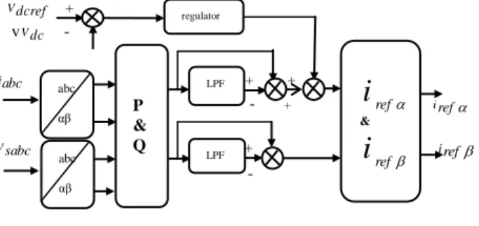
The instantaneous powers method introduced by H. Akagi and al. exploit the Concordia transformation of the voltages at the connection points of the parallel active filter and the currents absorbed by the pollutant load, in order to calculate the instantaneous real and imaginary powers[13].
Vdcref + vVdc - iabc + + - + iref Vsabc + iref -
Fig.5. Block diagram of the reference currents
The main steps of this method are summarized in the diagram blocks of Fig.5. The reference currents are identified using an instantaneous active and reactive power theory[14]. To scale back variations and instability within the DC link voltage, a Proportional-Integral (PI) regulator, with associate degree anti-windup compensation is projected for the DC link voltage regulation [15].
V. DESCRIPTION OF PREDICTIVE CURRENT CONTROL Predictive current control of SAPF is based on the truth that only a limit number of possible switching states can be generated by an inverter can be generated by an inverter and that models of the system can be used to predict the conduct of the variables for every switching state. All possible predictive current values in different voltage vectors of inverters at the next time can be acquired through the predictive function. The cost function can select optimal vector so that output current values of inverters approach to the given reference values quickly. Generally, MPCC scheme is shown in Fig. 6.It uses the system model to predict the future behavior of the variables to be controlled. The quality function or cost function or error between the reference and predicted values are calculated. The switching state that minimizes g is selected and applied during the next sampling period [16][17]. ( ) iref k 3 ip(k1) 7 ( ) i k 2L-VSI
Fig.6. Predictive current control block diagram.
A. Discrete-time mode
A discrete form of the filter current for a sampling time
s
T can be used to predict the future value of the filter current. The future filter current can be determined by[18]:
ˆ ( 1) (1 ) ( ) (V( ) e(k)) p RTs Ts i k i k k L L (3) Where
R
andL
are the output filter inductance and resistance, i k( )is the measured filter current, V( )k is voltage vector generated by SAPF, and ˆe( )k the estimated back-emf. ˆ( ) ( ) L ( ) (RTs L) ( 1) e k V k i k i k Ts Ts (4) B. Cost functionThe cost function is expressed in orthogonal coordinates and measures the error between the references and the predicted currents:
* *
| ( ) p ( 1)|+| ( ) p ( 1)|
g i k i k i k i k (5) Where, i*(k)&i*( )k are the real and imaginary parts of the reference current, and ip(k1)&ip(k 1) are the real and imaginary parts of the predicted filter current vector.
VI. MPCALGORITHM
The most important stages of control algorithm are [18]:
Extraction of reference compensating current
Measure the current injected in the filter.
Predict filter current for the next sampling instant for all the possible switching states.
Evaluate the cost function for each prediction.
Optimal switching state is selected which minimizes the cost function.
Apply the new switching state
VII. SIMULATION RESULTS AND DISCUSSION For the simulations, Matlab/Simulink and the SimPowerSystem toolbox were used. Various simulation results are obtained under ideal and non-ideal provide conditions. The simulation model parameters are shown in Table I.
TABLE I. SYSTEM PARAMETRS
Parameter Value AC supply voltage 100 V (rms) Supply resistor 0.1 Supply inductor 0.1 mH Supply frequency 50 Hz Load AC resistor 0.01 Load AC inductor 0.556mH DC voltage 280V DC capacitor 1000 F Filter resistor 0.01 Filter inductor 3mH Rectifier load resistor 26 Rectifier load inductor 10mH Boost capacitor 100 F Boost inductor 10mH
The proposed PV model is simulated using Matlab/ Simulink, at standard test conditions, the simulated I-V and PV characteristics are shown in Fig. 7.
P & Q abc αβ LPF regulator ref
i
& refi
LPF abc αβ Minimization of cost function Predictive model c b a S S S0 5 10 15 20 25 0 1 2 3 4 5 6 7 8 9 Voltage(V) C urre nt (A) 0 5 10 15 20 25 0 20 40 60 80 100 120 140 160 Voltage(V) Po w er(W )
Fig.7. Simulated I-V and P-V characteristics of the panel
0.04 0.06 0.08 0.1 0.12 0.14 0.16 0.18 -150 -100 -50 0 50 100 150 time(s) Vs a(V )
Fig.8. Source voltage waveform Vsa (v)
0.04 0.06 0.08 0.1 0.12 0.14 0.16 0.18 -10 -8 -6 -4 -2 0 2 4 6 8 10 time(s) iLa (A)
Fig.9. load current iLa (A)
0.04 0.06 0.08 0.1 0.12 0.14 0.16 0.18 -10 -8 -6 -4 -2 0 2 4 6 8 10 time(s) is a(A )
Fig.10. Source current isa (A) waveform before filtering
0.04 0.06 0.08 0.1 0.12 0.14 0.16 0.18 200 220 240 260 280 300 320 340 360 time(s) Vd c (V)
Fig.11. Vdc (V) bus waveform after filtering
0.04 0.06 0.08 0.1 0.12 0.14 0.16 0.18 -15 -10 -5 0 5 10 15 time(s) iSa (A)
Fig.12. Source current isa (A) waveform after filtering
0 2 4 6 8 10 12 14 16 18 20 0 5 10 15 20 Harmonic order Fundamental (50Hz) = 9.787 , THD= 27.51% M ag (% of F un da m en tal)
Fig.13. Source current spectrum without filter
0 2 4 6 8 10 12 14 16 18 20 0 5 10 15 20 Harmonic order Fundamental (50Hz) = 9.834 , THD= 1.22% M ag (% of F un da m en tal)
Fig.14. Source current spectrum with filter
Figure 8 shows the source voltages waveform purely sinusoidal and balanced. The load current as illustrated in figure 9. Figure 10 shows the source current waveform deformed before filtering. The dc-link capacitor voltage is adequately controlled around its reference value Vdc with a very slight ripple as illustrated in figure11. The active filter has imposed a sinusoidal source current waveform instantaneously as shown in figure12. Figure 13and 14 shows the spectrum analysis of the source current without/with a filter. The current THD (total harmonic distortion) is reduced from 27.51% to 1.22% on the grid network, which confirms the good quality of filtering after using an interactive shunt active power filter, the simulation results show a good filtering of harmonic currents and a perfect compensation of reactive power.
VIII. CONCLUSION
Model predictive current control algorithm is used to control the SAPF power switches to generate the opposite harmonics and to inject them at the point of common coupling (PCC) for compensating current harmonic and reactive power.
The simulation results obtained demonstrate the effectiveness and strength of the proposed system we have seen a good signal quality in terms of the current harmonic distortion THD 1.22% of three-phase source. So the proposed MPCC control is easy to implement and it shows robustness and very good performance in both balanced supply voltages.
Finally, the study of the photovoltaic compensation system, that we tend to mentioned during this paper, allowed us to obtain very good performance in injection of power produced by photovoltaic system to the distribution networks and compensate harmonics and reactive power.
REFERENCES
[1] M. Kesler and E. Ozdemir, “Operation of shunt active power filter under unbalanced and distorted load conditions,” 2009
Int. Conf. Electr. Electron. Eng. ELECO 2009, pp. 92–96,
2009.
[2] B. Subudhi, P. C. Panda, and R. Panigrahi, “Model predictive-based shunt active power filter with a new reference current estimation strategy,” IET Power Electron., vol. 8, no. 2, pp. 221–233, 2015.
[3] H. K. Lim, M. F. Sepikit, and M. Maskum, “photovoltaic Solar Energy Technology Overview for Malaysia Scenario” pp. 300– 305, 2003.
[4] M. Guisser1*, “Nonlinear Control Design for Maximum Power Point Tracking and Unity Power Factor of a Grid-Connected Photovoltaic Renewable EnergySystems\n,” IOSR J. Electron.
Commun. Eng., vol. 9, no. 5, pp. 62–71, 2014.
[5] G. Joga Rao, S. K. Shrivastava, and M. Gouse Baig, “Modeling and Simulation of Incremental Conductance Maximum Power Point Tracking (MPPT) Algorithm for Solar PV Array Using Boost Converter,” Ijsrset, vol. 4, no. 4, pp. 650–656, 2016. [6] J. Rodriguez and P. Cortes, Predictive control of power
converters and electrical drives. 2012.
[7] V. Yaramasu and B. Wu, Model Predictive Control of Wind
Energy Conversion Systems. 2017.
[8] J. Nan, H. Shiyang, C. Guangzhao, J. Suxia, and K. Dongyi, “Model-Predictive Current Control of Grid-Connected Inverters for Pv Systems,” Ieee, 2016.
[9] M. M. L. Rachid Belaidi, A. Haddouche, M.Hatti, “Shunt active power filter connected to a photovoltaic array for compensating harmonics and reactive power simultaneously,”
4th Int. Conf. Power Eng. Energy Electr. Drives, no. May, pp.
13–17, 2013.
[10] A. Kihel, F. Krim, and A. Laib, “MPPT voltage oriented loop based on integral sliding mode control applied to the boost converter,” 2017 6th Int. Conf. Syst. Control. ICSC 2017, no. 1, pp. 205–209, 2017.
[11] B. Boukezata, A. Chaoui, J. P. Gaubert, and M. Hachemi, “Active Power Filter in a Transformerless Grid Connected Photovoltaic System,” Balk. J. Electr. Comput. Eng., vol. 2, no. 3, pp. 122–127, 2014
[12] N. Mars, F. Grouz, N. Essounbouli, and L. Sbita, “Synergetic MPPT Controller for Photovoltaic System,” J. Electr. Electron.
Syst., vol. 6, no. 2, 2017.
[13] K. Rameshkumar, V. Indragandhi, K. Palanisamy, and T. Arunkumari, “Model Predictive Current Control of Single Phase Shunt Active Power Filter,” Energy Procedia, vol. 117, pp. 658–665, 2017.
[14] R. B. Udes, “Shunt active power filter connected to a photovoltaic array for compensating harmonics and reactive power simultaneously,” no. May, pp. 13–17, 2013.
[15] S. Ouchen, A. Betka, S. Abdeddaim, and A. Menadi, “Fuzzy-predictive direct power control implementation of a grid connected photovoltaic system, associated with an active power filter,” Energy Convers. Manag., vol. 122, pp. 515–525, 2016.
[16] J. Rodriguez et al., “State of the Art of Finite Control Set Model Predictive Control in Power Electronics,” IEEE Trans.
Ind. Informatics, vol. 9, no. 2, pp. 1003–1016, 2013.
[17] N. Mesbahi, “Predictive Current Controlled Shunt Active Power Filter Working under Unbalanced Supply Conditions,” pp. 2–5.
[18] J. Rodriguez, B. Wu, M. Rivera, C. Rojas, V. Yaramasu, and A. Wilson, “Predictive current control of three-phase two-level four-leg inverter,” Proc. EPE-PEMC 2010 - 14th Int. Power