To cite this document:
Prothin, Sebastien and Moschetta, Jean-Marc A Vectoring Thrust
Coaxial Rotor for Micro Air Vehicle: Modeling, Design and Analysis. (2013) In: 3AF -
48th International Symposium of Applied Aerodynamics, 25 March 2013 - 27 March
2013 (Saint Louis, France).
O
pen
A
rchive
T
oulouse
A
rchive
O
uverte (
OATAO
)
OATAO is an open access repository that collects the work of Toulouse researchers and
makes it freely available over the web where possible.
This is an author-deposited version published in:
http://oatao.univ-toulouse.fr/
Eprints ID: 9873
Any correspondence concerning this service should be sent to the repository
administrator:
[email protected]
A Vectoring Thrust Coaxial Rotor for Micro Air Vehicle:
Modeling, Design and Analysis
Sebastien Prothin(1), Jean-Marc Moschetta(2)
(1,2)
Institut Supérieur de l’Aéronautique et de l’Espace (ISAE), BP 54032 - 31055 Toulouse, France.
(1)
(2)
ABSTRACT: The growing interest of rotary wing UAVs, for military and civilian applications, has encouraged designers to consider miniaturized configurations, more efficient in terms of endurance, payload capability and maneuverability. The purpose of this paper is to study a new configuration of coaxial rotor as applied to a micro aerial vehicle (MAV) with the intention to guarantee the vehicle maneuverability while removing unnecessary control surfaces which would increase wind gust sensitivity. Coaxial rotor configurations maximize the available rotor disk surface and allow for torque cancelation. Tilting rotors may allow for the vehicle control.
1. INTRODUCTION
Miniaturizing MAVs requires satisfying stringent mass constraints as well as simple mechanisms which can be downscaled. Because it cancel the resulting torque and takes full advantage of the available disk surface, coaxial configurations have attracted the designers attention within the MAV community (A.P.K. Hall et al. [1]). Instead of resorting to swashplate cyclic pitch mechanisms which are fragile and difficult to miniaturize, the present study investigate tilting rotors as a control mode. The potential benefit from that kind of control is to get rid of any unnecessary control surface which would make the vehicle more sensitive to crosswinds. Eventually, the tilting mechanism shall be replaced by electroactive polymer actuators instead of the present servos. The present paper aims at studying a modified version of a conventional counter rotating coaxial rotor in which rotors may be tilted in order to create drift forces and moments potentially usable for maneuverability.
In the presented prototype, the direction of the thrust of the two rotors can be redirected by tilting propellers laterally and longitudinally. A theoretical model of the mechanism has been developed based on a mechanical model which includes forces, moments and gyroscopic effects induced by the rotating parts (Fig. 1, left). A simple coaxial model due to G. Leishman [2,3] has been implemented in order to account for both mechanical and aerodynamic effects.
In addition to the theoretical approach, an experimental setup has been developed. It is based on 5-component balance (Fig. 1, right) holding the coaxial system from above. For the present study only quasi-static measurements have been done. That configuration allows evaluating the forces and moments created by the many combinations of input parameters of the system. In this case, we also conduct a vibration analysis system in parallel configuration rotors. The experimental system has 6 inputs (Double angle control of the two rotors, and rotational speed control of the two motors) and 12 outputs (2 forces Fy / Fz, 3 torques Mx / My / Mz, the rotational speeds of the two rotors the voltage and current of the two motors, pressure and temperature). The rotors are regulated by a speed controller, and the rotors incidence is controlled via four servomotors, calibrated to + / - 0.1 °.
The methodology consists of several steps:
• Performance of each rotor at zero incidence
• Interaction of the two rotors, zero incidence
• Influence of static tilt rotors system at null iso-torque
• Stress analysis in the case of movement in tandem rotors (not shown in this article) • Influence of the tilt rotor dynamics
(temporal control law) system to at null iso-torque, gyroscopic effects analysis (not shown in this article)
Preliminary results have provided the motor speeds corresponding to a vanishing global torque,
and to assess the influence of the interaction rotors on the overall system performance. As a second step, it was shown that it was possible to use the tilt rotors to generate forces and moments to operate the system in flight.
The final paper will include a side-by-side comparison between the theoretical model and experimental data. In this first feasibility study will limit ourselves to a study of the model without flight, allowing to analyze and understand the mechanisms of the tilt rotors.
2. MODELING
In this section we perform a kinematic analysis of the mechanism, in order to understand, analyze and compare the experimental results obtained. This mechanism uses four servomotors (Fig. 1 (b)) for independently controlling the lateral and longitudinal tilt of the two rotors. The two external servomotors control the longitudinal tilting and the two internal actuators control the lateral tilting. In this preliminary study, the mechanism is attached to a five component balance to measure forces induced by the rotation and tilting of the rotors.
(a) Model (b) Prototype
Figure 1. Control mechanism based on pivoting rotors
(a) Longitudinal Tilt (b) Lateral Tilt
Figure 2. Coordinates systems
of the Upper and Lower rotor
In what follows we will present the equations of the dynamics of such a mechanism. To detail this analysis, we first define the following coordinates systems (Fig. 2):
• is linked to the coordinate
of the balance measuring global efforts.
• and are
linked to the Upper and Lower rotors (Fig. 2(a) and 2(b)).
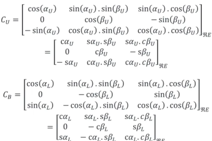
The positions of the rotors relative to the reference are determined by means of the passage
matrices and , parameterized by the
longitudinal and lateral tilt angles, respectively,
U,L et U,L :
Notation c for the cosine function and s for the sine function. If the rotors are parallel, these matrices become:
2.1 Thrusts of rotors
Rotating propellers produces thrusts, and , classically modeled by:
! "# ! "#
where the coefficients ! and ! , specified axial thrust which depends mainly on the geometry of the blades and the air density and with, " and " , are the rotational speeds of the propellers. When comparing with experiment, this model was robust in the case of a single propeller.
In our case the propellers being strong interaction, it was necessary to bring a more complex formulation of the type:
" " $ " % & " "
Where $ and $, are the propellers thrust off interaction, and & and & , differences thrust resulting from the interactions, respectively, of the upper on the lower and lower on the upper.
The propellers thrust off interaction, are modeled by :
$ " '((( "#% (( " $" '))) "#% )) "
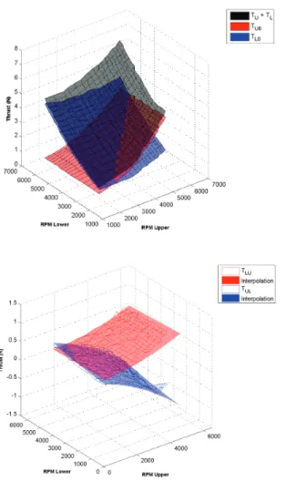
The coefficients ['((( (('))) ))* are constants dependent on type of propeller, and intrinsic to each propeller. These coefficients are determinate by tests on each propeller independently. The difference in thrust from mutual interactions is not so easy to model. In the case of the experiment presented in this paper, the access to the intrinsic measure of each propeller interaction was not possible. We therefore used a test bench to measure in the same flow condition, the efforts of individual helices. This bench has allowed us, firstly, to measure intrinsic performance of each propeller, but also to mount the propellers in the same configurations of interaction (Table 2). Figure 3 shows the measured thrust out for each propeller interaction and modeling described previously. This interpolation allows us to determine the coefficients ['((( (('))) ))* by the method of least squares. This interpolates values as:
'((( + , -./0 12 3 4 (( 56 -7/0 12 3
'))) 6 58 -. /0 12 3 4 )) +9 -7 /0 12 3
Then we can measure the efforts of the two propellers in the same conditions as for the prototype discussed later in this study. The difference being that we can evaluate the efforts of the two propellers. Thus it is possible to estimate the interaction terms & and & .
Figure 4 presents these results. We can see that the differences due to the mutual interaction are relatively low. It may be noted that the interaction is two-way, in fact, it was expected that the upper rotor interacts strongly with the lower rotor, but these results show that the lower rotor also affects the behavior of the upper rotor. A second remark can be made on the form of the interaction terms. We see that these two terms depend primarily on the speed of rotation of the upper rotor " .
In order to model the effort to analyze the behavior of the machine, we choose to represent the mutual efforts by the following model:
& " " '(()( "#% ()( " % ')))( "#% ))( "
% '())(" "
& " " '((() "#% (() " % '))() "#% )() "
% '()()" "
As previously, by the method of least squares, we can determine the coefficients. Both thrusts :; and :< can be expressed in ; and < coordinates:
:;; = :;*> :<< = :<*>
To find their expressions in the coordinate system related to the balance ? just use the passage
matrix @Aand @B :
CDEFEG G % G
2.2 Efforts of gravity
In this study, the forces due to gravity can be modeled as:
CHG = IJ *G
However, in this case, recordings efforts are made relative to fixed speed, and therefore the efforts of gravity will not be taken into account in the equations.
2.3 Torques of rotors
When the blades rotate they undergo drag producing torques, K and K are opposed to the rotational speed of the propellers:
K = K *E K = K *E
In general, a modeling of these couples, the type K L "# and K L "#, is well suited for an isolated propeller, or for the same reasons as above, we used a model of the type:
K " " K $ " % K& " "
K " " K$ " % K & " "
With, K $ and K$, the propellers torque off interaction, and K & and K & , differences torque resulting from the interactions, respectively, of the upper on the lower and lower on the upper.
The propellers torque off interaction, are modeled by :
K $ " M((( "#% N(( "
K$ " M "#% N "
The coefficients [M((( N((M))) N))* are constants dependent on type of propeller, and intrinsic to
each propeller. These coefficients are determinate by tests on each propeller independently. The difference in torque from mutual interactions determined, as before, by measurements on another test bench.
Figure 5 shows the measured torque for each propeller interaction and modeling described previously. This interpolation allows us to determine the coefficients [M((( N((M))) N))* by the method of least squares. This interpolates values as:
M((( O, -P/30 12 3 4
N(( 8 O+ -Q/30 12 3
M))) 8 -P /30 12 3 4
N)) + -Q /30 12 3
Then we can measure the efforts of the two propellers in the same conditions as for the prototype discussed later in this study. The difference being that we can evaluate the efforts of the two propellers. Thus it is possible to estimate the interaction terms K & and K & .
Figure 6 presents these results. We can see that the differences due to the mutual interaction are relatively low. It may be noted that the interaction is two-way, in fact, it was expected that the upper rotor interacts strongly with the lower rotor, but these results show that the lower rotor also affects the behavior of the upper rotor.
In order to model the effort to analyze the behavior of the machine, we choose to represent the mutual efforts by the following model:
K & " " M(()( "#% N()( " % R "$ 7
K & " " M((() "#% N(() " % M))() "#% N)() "
% M()() " "
As previously, by the method of least squares, we can determine the coefficients. As before can express these torque in the reference :
S EFEG KG % KG
2.4 Balance reaction
In this study, we consider a mechanism outside flight, in order to analyze and understand the different interactions that can occur. Therefore, the mechanism is attached to a 5 components balance modeled like this:
CT U) = CV CW CX*E
ST U) = SV SW SX*E
2.5 Torques due to the thrusts
As the rotors rotate around two points, distinct of the center of gravity, the thrust force generates a torque. Y YZZZZZZZZ[ = ! *E and Y YZZZZZZZZ[ = ! *E are defined as the position vectors expressed in , points of application of thrusts and , respectively. Thus the torque produced by the thrusts of the center of gravity O and expressed in W is given by:
\]>^>G? _@; :;G;`aY YZZZZZZZZ[ % _@<:<G<`aY YZZZZZZZZ[
2.6 Gyroscopic moments
During the rotation of an object around a given axis, a gyroscopic torque appears perpendicular to these two axes. The tilt of a rotor with a certain angle giving rise to a gyroscopic torque, which is the vector product of the angular momentum vector of the rotor and the tilting speed. These moments are expressed in the rotor coordinate as follows: Longitudinal Tilt : S b cd " e Sb cd " e S b = S b *E S b = Sb *E Lateral Tilt :S f cd " e Sf cd " e S f g S f hE Sf g Sf hE
cd is the moment of inertia of the rotors relative to
their rotational axes X and X. These moments expressed in the coordinate system , lead to the following expressions :
SbEFEG SGb % SGb
SfEFEG SGf% SGf
2.7 Reaction moments of servomotors
This parasitic moment is caused by the pivoting of each rotor. When a servomotor apply a torque on the rotor for the tilting, resulting in a inverse reaction torque Si. This moment depends on the acceleration j and j . These moments are expressed as follows : Longitudinal Tilt : Sib cE j Sib cE j Sib = Si b *E Sib = Sib *E Lateral Tilt : Si f cE j Sif cE j Sif g Sif hE Sif g Sif hE
cE is the moment of inertia of the rotors relative to
their rotational axes V and V. These moments expressed in the coordinate system , lead to the following expressions :
SibEFEG SiGb % SiGb
SifEFEG SiGf % SiGf
2.8 Equations of motion
The equations of motion are obtained by applying the fundamental principle of dynamics:
kl C
m
l S m
Which in this case is reduced, for the forces to:
CTnU)G CEFEG
And for the moments :
ST U) S EFEG \]>^>G? SbEFEG SfEFEG
SibEFEG SifEFEG
In this study, we will take measures in the case of Static tilting. That is to say that the measurements are performed after tilting rotors to get rid of any transitional period. The study of these particular periods will be studied later.
This assumption leads to the point of view of the setting mechanism :
e j
e j
This setting causes the point of view of the efforts :
S b , Sb ; S f , Sf Sib , Sib ; Si f , Sif The forces equation become :
CT U) CDEFEG
= CV CW CX*o G G
And the moments equations :
ST U) S EFEG \]>^>G?
= SV SW SX*o KG KG _@; :;G;`aY YZZZZZZZZ[
_@<:<G<`aY YZZZZZZZZ[
Thanks to these equations of motion, it is possible for us to determine the forces that are applied to the machine. In the next section we will compare the measurements with the analytical model created (Figure 7).
3. FACILITY AND MODEL DESCRIPTION
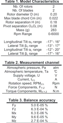
The characteristics of the model are presented in Table 1. The model is mounted on a fixed frame, outside containment. Particular attention has been paid with respect to the reduction of
vibrations. Measurement channels are
summarized in Table 2.
Used propellers are propellers trade characterized in the laboratory. The motors are brushless type,
Roxxy Robbe BL-Motor 2824-34, the control of
these motors is performed by, TopModel Xreg10
power speed controllers, modified to allow
measurement of the rotational speed. The rotors are strongly interacting, it was set up, program control, closed-loop system of the two rotors, to enslave them directly by the regime wanted value. This control permits precision in speed to 0.5%. The tilting of the rotors is achieved by four servomotors:
TopModel, Digital Servo DS4308 MG
Torque : 4.3 kg.cm Speed : 0.08 ‘’ / 40° to 4.8V Mass : 24g
allowing a range of tilting specified in Table 2. Laws control the servomotors to know the incidence of rotors with precision (+ / - 0.1 °) passes through a calibration phase. This calibration is for all the positions of the servomotors to measure the incidence in the coordinate .
This measure of incidence is effected by means of a laser displacement sensor, Keyence IL-300, which is used to extract a grid of points on the rotor disk, and to a plane by interpolation to know the incidence of the it accurately. This calibration is performed to a large number of positions of the servomotors, and can be determined for a calibration matrix inversion to obtain two control laws of the type:
N pIqr pIqs N pItr pIts
with pIqr, pIqs, pItr and pIts, the
Figure 3. Thrust measurement for two propellers off
interaction
Figure 4. Measuring thrust interaction
Top : Total thrust and thrust off interaction Bottom : Difference thrust due to mutual interaction
Figure 5. Torque measurement for two propellers off
interaction
Figure 6. Measuring torque interaction
Top : Total torque and thrust off interaction Bottom : Difference torque due to mutual interaction
Figure 7. Inputs and outputs
of the analytical model
The mechanical design for the double tilt rotor requires each non-linearity of these laws. Therefore to properly represent them and thus increase the accuracy, the calibration was performed automated way to scan 441 control
pairs pIqr/ pIqs and pItr/ pIts.
The measurement of the forces due to the interactions and tilting of the rotors is performed by means of a five-component balance dart built by l'IAT Saint-Cyr l'École. It is in the form of a bar of square section steel, and 9 cm in length with five measuring bridges to strain gauges. It allows the measurement of two components of force FY and FZ and three moment components MX, MY and MZ. This balance has a maximum capacity of 10 N is conditioned by five amplifier / filter E-325, which feeds the bridge balance with a nominal voltage of 4 V. Is then the acquisition of these signals through a National Instrument card.
The use of this balance through its calibration to match each measuring bridge component of the force torsor applied to the balance. Bridges are coupled, the calibration was therefore to address these output voltages and provide force components decoupled. A steel plate with nine points fixed application shanks on the bar. This board allows, thanks to its high precision application points, applying ad hoc efforts on the balance. A program was then used to complete the acquisition.
Each measuring point is the average of 1000 acquisitions to the frequency of 500Hz, for 459 pairs mass / position. Through conventional treatment it was possible to go back the matrix calibration static balance, allowing to determine the forces on the basis of measured voltages with high accuracy (Table 2).
Acquisitions of different measurement channels was made at a frequency of 2kHz, (15s and 30000 samples), allowing statistical convergence of the standard deviation of effort.
A correction is applied to the measurement of rotational speed and effort, to take into account the
variations in atmospheric pressure and
temperature during testing.
This correction is applied to the instantaneous signals is summarized by the relationship:
"u " v 'w0 $ CW Xu x'CW X w0x'$ SW Xu x'SW X w0x'$
The exponent c corresponding to the corrected values, the index i is the raw signal, T0 and Pa0 are the standard value of temperature and pressure, respectively, 288.15K and 101325 Pa.
Table 1. Model Characteristics
Nb. Of rotors 2 Nb. Of blades 2 Rotor diameter D (m) 0.20 Max blade chord Cm (m) 0.022
Rotor separation H (m) 0.18 Pivot separation OUOL (m) 0.08 Mass (g) 283 Rpm Range 0-6000 Longitudinal Tilt U range -17° - 16° Lateral Tilt U range -13° - 17° Longitudinal Tilt L range -12° - 20° Lateral Tilt L range -17° - 16°
Table 2. Measurement channel
Atmospheric pressure, Pa atm Atmospheric temperature, Ta °C
Supply voltage, U V Current, IU,L A Rotation speed, RPMU,L Rpm Force Components, FY,Z N Torque Components, MX,Y,Z N.m
Table 3. Balance accuracy
Fy 5.0 E-05 % Fz 6.3 E-04 % Mx 6.3 E-06 % My 9.6 E-05 % Mz 2.7 E-04 %
Measurements used for this study are divided into three distinct parts.
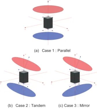
First part, case 1, of studying the behavior of the device without tilting in conventional operation of coaxial rotors (Fig. 8a), which requires the setting for the model that ; ; < < .
This configuration will allow us to readjust the theoretical model to experimental data, and so determining, empirically and by an optimization method, the coefficients intrinsic rotor upper and lower, respectively !; "; "< , !< "; "< , L; "; "< , et L< ";"< . yzy{ | }~ |€ ~ |• ~ ‚z ~ ƒz ~ ‚{~ ƒ{ ~ „}~ „€ ~ „•~
This step will be explained in the results section. This part will also determine the pairs of rotational speeds ";0"<, allowing cancellation of the resulting torque Mz, which will be used in the following parts.
The following two cases studied concern, this time, the tilting of the rotors. The speeds are fixed at values generating a resultant torque equal to zero. The two cases are distinguished by the inclination of the two rotors.
The starting point of this study is the control device, type MAV. The choice of rotor tilt control has been done to try to generate pure transverse forces (FX,Y) or pure moments (MX,Y). Therefore,
certain symmetry was observed regarding the movements of the rotors.
Case 2, called "Tandem Rotor" (Fig. 8b) is applied to the lower rotor tilt symmetrical allowing the upper to keep the two parallel rotors, implying as parameters:
Case 3, called "Rotor Mirror" (Fig. 8c) is applied to the lower rotor tilt antisymmetric involving as parameters:
Table 4 shows the parameters used for the different cases studied.
(a) Case 1 : Parallel
(b) Case 2 : Tandem (c) Case 3 : Mirror
Figure 8. Tilt configuration
4. RESULTS
4.1 Case 1
This section presents the results for Case 1, of studying the behavior of the device without tilting in conventional operation of coaxial rotors (Fig. 8a), This parameterization leads to the model, a cancellation of four components of efforts (FX,Y & MX,Y). The two remaining components
corresponding to the vertical thrust and the yaw moment of the vehicle. The measurement performed on the model confirm this. Figures 9 and 10, shows the results of the force measurements as a function of rotational speeds of the two motors, for the case 1. Figures 9 and 10, respectively, represent the component Fz and Mz efforts function of RpmU and RpmL. This
figures represents the iso-components of forces (Fz and Mz) in diagrams RpmU / RpmL. These
same figures also represent the comparison of our optimized model to data from the experiment. Because of interactions between the two rotors, the efforts on the system are not symmetrical in space RpmU / RpmL. Indeed, if the two propellers
had the same behavior in interaction, efforts would be symmetrical about the line RpmU = RpmL.
However, as shown in Figures 9 and 10, this is not the case. Propellers having the same intrinsic characteristics, this is because the lower propeller sees a flow different to the upper propeller, disturbed by it. Regarding the comparison between the measurements and the analytical model, we observe a very good representation of the data. We have chosen three values of the pairs
RpmU / RpmL, corresponding to a cancellation of
the resulting torque Mz (yaw moment), which will be used for the following two scenarios (cases 2 and 3). In this paper we will focus on a point of fixed speed (RpmU / RpmL = 5000/4955) and
variations in tilt angle of about 12°.
4.2 Case 2
Case 2 corresponds to the case in "Tandem", is to tilt the rotors so as to allow parallel. In this study,
we have chosen to present the results
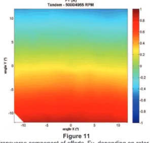
corresponding to speeds 5000/4955, respectively, the velocities of Upper and Lower rotor. In this case, the force measurements have shown that only two of the five components are nonzero, Fy and Fz. The vertical force component Fz, is almost constant in 3.68N, while the transverse component Fy varies (Fig. 11). It is clear that the switching of the two rotors in tandem creates a pure strain, transverse and linearly related to the tilt angle. Even without its extent, it is possible to imagine that the other transverse component, Fx, in the same behavior, and those thanks to the symmetry of the assembly.
4.3 Case 3
Case 3 "Mirror", corresponds to the antisymmetric tilting of the two rotors. In this case, the efforts we show that the measured transverse forces (Fx and Fy) are zero, the vertical force Fz is almost constant 3.54N, and the roll and pitch angles are proportional to the tilt (Fig. 12 & 13). We see these results as pitch and roll moments are relatively linear function of the angles and tilt rotors. In the case of antisymmetric tilting rotors, efforts created, in addition to vertical thrust, correspond to pure moments.
Iso-Fz versus RpmU & RpmL
Thick lines : Measurments Thin lines : Theoretical model Black line : RpmU = RpmL
Figure 9. Case1
Comparison between the theoretical model and experimental data, for the Fz component
Iso-Mz versus RpmU & RpmL
Thick lines : Measurments Thin lines : Theoretical model Black line : RpmU = RpmL
Figure 10. Case1
Comparison between the theoretical model and experimental data, for the Mz component
Figure 11
Transverse component of efforts, Fy, depending on rotor tilt angles, corresponding to RpmU / RpmL = 5000/4955, at
constant zero torque Mz, for the Tandem case.
Figure 12
Transverse component of efforts, Fx, depending on rotor tilt angles, corresponding to RpmU / RpmL = 5000/4955, at
constant zero torque Mz, for the Mirror case.
Figure 13
Transverse component of efforts, Fy, depending on rotor tilt angles, corresponding to RpmU / RpmL = 5000/4955, at
constant zero torque Mz, for the Mirror case.
5. DISCUSSION
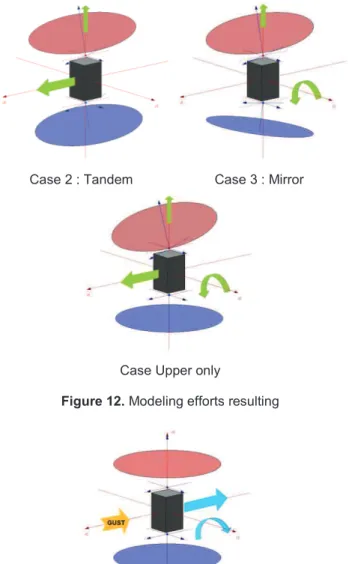
Figure 12 shows a synthetic way, efforts created during tilting rotors. These results show that the tilting of the rotors can be used to generate pure forces or moments pure. Thus it is possible to use these efforts in order to control the drone, replacing conventional control surfaces.
Figure 13 shows the forces induced by a gust of wind on the drone. We see that in the case of a gust of wind, we create a drift, and a pitch down moment. We see that in this case it is interesting to tilt one of the rotors to create opposing forces and moments, thus stabilizing the drone.
All these findings are made in the case of static displacement, the gyroscopic efforts arising from the dynamic tilting are not taken into account. Following this study, we analyze the system behavior dynamically, by applying of the temporal tilting laws. In this case, we will create gyroscopic efforts that can be interesting for the control of the drone.
Future work will focus on a prototype maintained within a fixed frame and allowed to rotate on a growing number of degrees of freedom.
6. ACKNOWLEDGEMENTS
I want to thank the foundation STAE / RTRA who contribute to this project in the project EMMAV (Electro for Morphing Micro Air Vehicle). I would also like to thank the technical staff of the department of aerodynamics ISAE, especially Remy Chanton without whom, this study would not have been possible.
REFERENCES
1. Hall, A. P. K., Wong, K. C., A. Doug. "Coaxial Aero-Mechanical Analysis of MAV Rotorcraft with Rotor Interaction for
Optimisation”. 12th AIAA/ISSMO
Multidisciplinary Analysis and Optimization Conference, Victoria, British Columbia, Canada, September 10 – 12, 2008.
2. Leishman, J. G., “Principles of Helicopter Aerodynamics”, 2nd ed., Cambridge Univ. Press, New York, 2006.
3. Leishman, J. G. and Ananthan, S., "Aerodynamic Optimization of a Coaxial Proprotor," 62nd Annual National Forum of the American Helicopter Society, Phoenix, AZ, May 9-11, 2006.
Case 2 : Tandem Case 3 : Mirror
Case Upper only
Figure 12. Modeling efforts resulting