Pépite | L'étude des comportements mécaniques des renforts et des propriétés d'usinage lors de la fabrication de composites de formes complexes
129
0
0
Texte intégral
(2) Thèse de Shenglei Xiao, Université de Lille, 2019. University of Lille. Dalian University of Technology. ACKNOWLEDGEMENTS. Firstly, I would like to sincerely appreciate the endless support from my supervisors: Prof. Damien SOULAT, Prof. Hang GAO and Prof. Peng WANG. Their consistent concern and valuable guidance always help me in all time of research and writing of this thesis. All my Ph.D supervisors have remained kind throughout and encouraged me to do what I want in project. Back to beginning of this thesis, I am very grateful for the special thanks to Prof. Peng WANG and Prof. Hang GAO, the former gave me this co-joint program that not every Ph.D. student in CHINA could get. The latter allows me to take this opportunity to broaden horizons not only in my growing professional knowledge but also in the aspect of life experience. I also want to express my gratitude to my contemporary friends or colleagues in GEMTEX: Chan HUI, Hao SHEN, Chen CHEN, Mengru LI, Imen GNABA, Vivien BAEEAL, Henri LANSIAUX for technical discussions and knowledge-sharing during my time in research. I am also indebted to my family members: my parents, Peiyi XIAO, Cuiping WANG; my wife, Yixuan FU; my elder brother and his wife, Shengbing XIAO, Huiying LIU, for their enduring love and support even I had been depressed and self-abandonment before I became a Ph.D. Especially for my wife, who made a huge sacrifice to support what I want to do, and endures I used to concentrate on my research neglecting the ordinary and peaceful life, which is indeed a driving force for my work and the source of true happiness. Lastly, I would like to thanks my Ph.D. friends and colleagues who are working or studying in CHINA for helping me to do a lot of things including experimental tests or trivia in life when I was studying abroad.. I © 2019 Tous droits réservés.. lilliad.univ-lille.fr.
(3) Thèse de Shenglei Xiao, Université de Lille, 2019. University of Lille. Dalian University of Technology. ABSTRACT Title: The Investigation on Mechanical Behaviours of Reinforcements and Machining Properties during Manufacturing Composites with Complex Shapes. The mechanical characteristics and deformability behaviours of reinforcements are essential knowledge to acquire desired quality during manufacturing composites with complex shapes. Meanwhile, the machining properties of composites also greatly determine the corresponding service performance of composites parts. Hence, this thesis is concentrating on the two aspects in manufacturing and machining processes to explore what characters the special features in the mechanical properties and deformability behaviours of braided fabrics, which are promising and excellent textile reinforcements for composites with complex shapes, and investigate the machining composites using abrasive waterjet technique through improvement in process to further enhance the machining efficiency without sacrifice of quality. The mechanical characteristics of braided fabrics, especially for in-plane shearing phenomenon, were originally investigated and modelled based on bias-extension test. Besides, the triaxial braided fabrics were also experimentally investigated in mechanical characteristics with respect to braiding parameters including braiding angle and number of yarns. The deformability behaviours of triaxial fabrics during preforming process were integrally discussed and correlated with the corresponding defects based on the different preforming pressures. Meanwhile, the mechanical models were proposed to further realize the law behind the deformability behaviours. The variation of deformability behaviours according to braiding angle was predicted through an approach of geometrical model and verified by experimental results. It is inferred that the geometrical analysis could show a well correlation with results to a certain degree. The upgraded multi-pass cutting of abrasive waterjet was firstly introduced into composites machining process based on the exploration of the corresponding material removal mechanism. It was experimentally concluded that such technique could effectively enhance the machining quality and efficiency.. II © 2019 Tous droits réservés.. lilliad.univ-lille.fr.
(4) Thèse de Shenglei Xiao, Université de Lille, 2019. University of Lille. Dalian University of Technology. CONTENTS GENERAL INTRODUCTION ............................................................................................... 1 Problems statement .............................................................................................................2 Thesis overview ..................................................................................................................3 Ӏ. STATE OF THE ART.........................................................................................................5 1.1 Introduction ..................................................................................................................6 1.1.1 The Composites .....................................................................................................6 1.1.2 The woven and braided reinforcements ................................................................ 10 1.1.3 Liquid composite moulding (LCM) process for manufacturing composites .......... 14 1.2 The mechanical behaviours of reinforcements ............................................................. 16 1.3 The stage of preforming .............................................................................................. 20 1.4 The composites machining by abrasive waterjet (AWJ) .............................................. 23 1.5 Conclusion of Chapter Ⅰ .............................................................................................. 27 Ⅱ. MECHANICAL BEHAVIOURS OF BRAIDED REINFORCEMENTS .......................... 29 2.1 Introduction ................................................................................................................ 30 2.2 An analysis of in-plane shear behaviours of braided preforms ..................................... 30 2.2.1 Geometric condition ............................................................................................. 30 2.2.2 Analytical model for shearing angle and moment ................................................. 31 2.2.3 Experimental method and materials ...................................................................... 33 2.2.4 Results and discussion .......................................................................................... 35 2.3 The influence of preforms parameters on mechanical and thermal behaviours of tubular braided reinforcements ..................................................................................................... 42 2.3.1 Materials and methods ......................................................................................... 42 2.3.2 Results and discussion .......................................................................................... 45 2.4 Conclusion of Chapter Ⅱ ............................................................................................. 52. III © 2019 Tous droits réservés.. lilliad.univ-lille.fr.
(5) Thèse de Shenglei Xiao, Université de Lille, 2019. University of Lille. Dalian University of Technology. Ⅲ. AN EXPLORATION ON PREFORMING PROCESS .................................................... 53 3.1 Introduction ................................................................................................................ 54 3.2 Tested materials and experimental set-up .................................................................... 54 3.2.1 Tested fabrics .......................................................................................................54 3.2.2 Preforming machine and experimental set-up ....................................................... 56 3.3 Deformability behaviours-general results and discussion............................................. 57 3.3.1 Yarns sliding ........................................................................................................ 58 3.3.2 In-plane shearing ..................................................................................................63 3.3.3 Preforming drawbacks.......................................................................................... 64 3.3.4 Variation of deformability behaviours influenced by braiding angle ..................... 66 3.4 The mechanical model for yarns and geometrical model for yarns sliding ................... 67 3.4.1 The mechanical model for yarns ........................................................................... 68 3.4.2 The geometrical model for yarns sliding ............................................................... 73 3.5 The law bebehind variation of in-plane shearing and material draw-in impacted by braiding angle ................................................................................................................... 79 3.6 Conclusion of Chapter Ⅲ ............................................................................................ 82 Ⅳ. THE INVESTIGATION OF FIBRE REINFORCED COMPOSITES MACHINING BY ABRASIVE WATERJET TECHNIQUE .............................................................................. 84 4.1 Introduction ................................................................................................................ 85 4.2 Materials and experimental set-up ............................................................................... 85 4.3 The material removal mechanism of fibre reinforced composites by AWJ machining . 87 4.4 The evaluation of kerf quality produced by multi-pass cutting process ........................ 90 4.4.1 Kerf taper ............................................................................................................. 91 4.4.2 Surface quality ..................................................................................................... 95 4.5 Conclusion of Chapter Ⅳ ........................................................................................... 98 Ⅴ. GENERAL CONCLUSION .......................................................................................... 100 5.1 Conclusion ................................................................................................................ 101 IV © 2019 Tous droits réservés.. lilliad.univ-lille.fr.
(6) Thèse de Shenglei Xiao, Université de Lille, 2019. University of Lille. Dalian University of Technology. 5.2 Perspectives .............................................................................................................. 102 Reference ........................................................................................................................... 103 Abstract .............................................................................................................................. 116 Résumé .............................................................................................................................. 117. V © 2019 Tous droits réservés.. lilliad.univ-lille.fr.
(7) Thèse de Shenglei Xiao, Université de Lille, 2019. University of Lille. Dalian University of Technology. LIST OF FIGURES Chapter Ⅰ Fig. 1.1. The example of a schematic illustration of composite material structure. ..................7 Fig. 1.2. The application of FRP; (a) Large-size carbon fibre reinforced plastic (CFRP) composites component used in airbus 350; (b) Main applications distribution for FRP. ..........7 Fig. 1.3. The examples of FRPs with complex shapes ........................................................... 10 Fig. 1.4.Lamina fibre reinforced composite: (a) Lamina with 2D woven fabric; (b) Laminate made by stacking laminas in different orientations. ............................................................... 10 Fig. 1.5. Typical 3D woven architectures: (a) Layer-to-layer angle interlock; (b) Throughthickness angle interlock; (c) Orthogonal. ............................................................................. 11 Fig. 1.6. Braiding process and braiding fabrics. .................................................................... 12 Fig. 1.7. The biaxial and triaxial braids strcture: (a) Biaxial; (b) Triaxial. ............................. 13 Fig. 1.8.Resin Transfer Moulding injection process. ............................................................ 15 Fig. 1.9. Illustration of thermal stamping process: (a) Heating die set and punch; (b) Heating specimen through heat transfer; (c) Thermal stamping. ......................................................... 16 Fig. 1.10. Two principle methods to determine in-plane shearing behaviours of woven fabric: (a) Bias-extension test; (b) Picture frame test. ....................................................................... 18 Fig. 1.11. Some typical preform shapes, (a) Hemisphere, (b) Square and (c) Tetrahedron ..... 21 Fig. 1.12. The performing defects: (a) Local wrinkles and buckles; (b) The amplification of buckles. ................................................................................................................................ 22 Fig. 1.13. The characteristics of AWJ, (a) the kerf wall properties, (b) the basic parameters in AWJ and (c) the kerf cross-section profile ............................................................................ 25 Fig. 1.14. The improvements in AWJ ................................................................................... 26. Chapter Ⅱ Fig. 2.1. A rectangular specimen of preform ......................................................................... 31 Fig. 2.2. Deformation of the braided preform sample during bias extension test, (a) initial state and (b) deformed state .......................................................................................................... 32. VI © 2019 Tous droits réservés.. lilliad.univ-lille.fr.
(8) Thèse de Shenglei Xiao, Université de Lille, 2019. University of Lille. Dalian University of Technology. Fig. 2.3. Tested preforms made by two materials after cutting and opening, (a) Flax/PA12 fibres reinforced braid and (b) E-glass fibres reinforced braid ............................................... 34 Fig. 2.4. The preforms before and during bias-extension test, (a) Flax/PA12 braided sample in AD and (b) E-glass Braided sample in TD ............................................................................ 36 Fig. 2.5. Load vs. displacement in AD for Flax/PA12 braided samples with different geometric ratios r.................................................................................................................. 37 Fig. 2.6. Load vs. displacement in AD for E-glass braided samples with different geometric ratios r .................................................................................................................................. 37 Fig. 2.7. Shear moment vs. shear angle in AD for flax/PA12 braided samples with different geometric ratios r.................................................................................................................. 38 Fig. 2.8. Shear moment vs. shear angle in AD for E-glass braided samples with different geometric ratios r.................................................................................................................. 39 Fig. 2.9. The complete in-plane shearing behaviour for braided preforms ............................. 40 Fig. 2.10. Comparison between the theoretical models and experimental results for Flax/PA12 braided preforms .................................................................................................................. 41 Fig. 2.11. Comparison between the theoretical models and experimental results for E-glass preforms ............................................................................................................................... 41 Fig. 2.12. Braiding machine in GEMTEX laboratory ............................................................ 43 Fig. 2.13. The braiding pattens as braiding angle 45° ............................................................ 43 Fig. 2.14. Test machine with preforms .................................................................................. 44 Fig. 2.15. Thermal behaviour conducted by the thermal camera during the test ..................... 45 Fig. 2.16. The tensile behavior for three groups of braided samples, (a) large, (b) middle, (c) small..................................................................................................................................... 46 Fig. 2.17. Influence of braided angle on (a) maximal deformation, and (b) maximal load at the second peak .......................................................................................................................... 47 Fig. 2.18. Influence of the number of the axial yarns on the maximal load at the first peak ... 47 Fig. 2.19. The evolution of braiding angle during tensile test, (a) large, (b) middle and (c) small..................................................................................................................................... 48. VII © 2019 Tous droits réservés.. lilliad.univ-lille.fr.
(9) Thèse de Shenglei Xiao, Université de Lille, 2019. University of Lille. Dalian University of Technology. Fig. 2.20. The temperature evolution with different braiding angle during tests, (a) large, (b) middle and (c) small ............................................................................................................. 50 Fig. 2.21. Maximum temperature in function of number of axial yarns ................................. 50 Fig. 2.22. Temperature and load evolutions during test for (a) sample 6-1-29 and (b) 6-3-48 51 Fig. 2.23. Evolutions of temperature and braiding angle during tests for (a) sample 6-1-29 and (b) 6-3-48 ............................................................................................................................. 52. Chapter Ⅲ Fig. 3.1. Tested triaxial braided preforms, (a) the structure, (b) a single yarn profile and (c) a locally specific profile of preform ......................................................................................... 55 Fig. 3.2. The details of (a) preforming machine and (b) numbered yarns ............................... 57 Fig. 3.3. The fabrics after preforming, (a) triaxial fabric and (b) woven fabric ...................... 58 Fig. 3.4. Maximum sliding along longitudinal yarn direction in function of different blankholder pressures .................................................................................................................... 59 Fig. 3.5. The yarn sliding along longitudinal yarn direction, (a) the overall profile of sliding performance and (b) the non-identical sliding of bias yarns................................................... 60 Fig. 3.6. Sliding of axial yarns along radial yarn direction, (a) the sliding phenomenon in the useful zone and (b) the depiction of sliding ........................................................................... 61 Fig. 3.7. Axial yarns sliding along radial yarn direction with different blank-holder pressures in the useful zone.................................................................................................................. 62 Fig. 3.8. The bias yarns sliding, (a) sliding and (b) its extend for each bias yarn ................... 63 Fig. 3.9. The in-plane shearing towards to the transversal direction.......................................63 Fig. 3.10 The maximum punch force and the mean in-plane shear angle vs. the blank-holder pressure ................................................................................................................................ 64 Fig. 3.11. The large extent of yarns sliding along longitudinal yarn direction ........................ 65 Fig. 3.12. The gaps and buckling in the useful zone .............................................................. 66 Fig. 3.13. The experimental result by braided angle 30° ........................................................ 67 Fig. 3.14. The experimental result by braiding angle 65° ...................................................... 67. VIII © 2019 Tous droits réservés.. lilliad.univ-lille.fr.
(10) Thèse de Shenglei Xiao, Université de Lille, 2019. University of Lille. Dalian University of Technology. Fig. 3.15. Sliding occurring during preforming. (a) Geometrical position of N°i axial yarn relative to punch tool, (b) N°i axial yarn formed by punch tool ............................................. 69 Fig. 3.16 The schematic diagram describes the tension generated during the preforming ...... 70 Fig. 3.17. The diagram presents the load transfer through a crossover region between upper plate and die in theory, (a) the area of crossover and (b) free body diagram in random crossover .............................................................................................................................. 71 Fig. 3.18. N°i bias yarn after preforming............................................................................... 72 Fig. 3.19. The experimental results concering maximum yarns sliding with different braiding angles ................................................................................................................................... 75 Fig. 3.20. Comparison between theoretical and experimental results with braiding angles 55° and 65° ................................................................................................................................. 75 Fig. 3.21. The difference between the ends for each bias yarn, S d , varied with different braiding angles .................................................................................................................... 77 Fig. 3.22. The comparison between the theoretical and experimental value of sliding for each bias yarn; (a) braiding angle 55°, (b) braiding angle 65° ....................................................... 78 Fig. 3.23. The 2D diagram to describe in-plane shearing during preforming process ............. 79 Fig. 3.24. The variation of in-plane shearing angle in the in-plane shearing zone at braided angle 55° .............................................................................................................................. 80 Fig. 3.25. The change of segmental yarn length in punch shape with different braided angles, (a) β/2=45°, (b) β0/2=30°, (c) β1/2=55°and (d) β2/2=65° ....................................................... 81 Fig. 3.26. The variation of in-plane shearing angle with different braided angles .................. 82. Chapter Ⅳ Fig. 4.1. Kerf characteristics in multi-pass cutting, (a) kerf shape at first-pass cutting (nonthrough cutting), (b) kerf shape at multi-pass cutting and pits and (c) enlarged microphoto of pits at bottom of kerf wall ..................................................................................................... 88 Fig. 4.2. The three zones generated by AWJ cutting, (a) IDZ, (b) SCZ and (c) RCZ ............. 89 Fig. 4.3. End of fibres in SCZ and RCZ, (a) 90° and (b) 45° ................................................. 89. IX © 2019 Tous droits réservés.. lilliad.univ-lille.fr.
(11) Thèse de Shenglei Xiao, Université de Lille, 2019. University of Lille. Dalian University of Technology. Fig. 4.4. Comparing the distinct zones machined with different traverse speeds, (a) a multipass cutting at 2300mm/min traverse speed, (b) a single-pass cutting at 400mm/min traverse speed .................................................................................................................................... 90 Fig. 4.5. Comparing kerf taper produced by multi-pass cutting with constant and changed parameters including pressure and traverse speed ................................................................. 93 Fig. 4.6. Cutting time and kerf taper in multi-pass cutting process ........................................ 95 Fig. 4.7. Comparing Ra produced by multi-pass cutting constant and changed parameters ..... 97. X © 2019 Tous droits réservés.. lilliad.univ-lille.fr.
(12) Thèse de Shenglei Xiao, Université de Lille, 2019. University of Lille. Dalian University of Technology. LIST OF TABLES Chapter Ⅰ Table 1.1. Comparison of characteristics between composite materials and metals .................8 Table 1.2. Mechanical properties of natural fibres as compared to conventional reinforcing fibres. .....................................................................................................................................9. Chapter Ⅱ Table 2.1. The main properties of the preforms ..................................................................... 34 Table 2.2. The characteristics of two preforms ...................................................................... 35 Table 2.3. Properties of ultra-high-molecular-weight polyethylene [19] ................................ 42 Table 2.4. The nomenclature of triaxial preforms .................................................................. 43. Chapter Ⅲ Table 3.1. The main properties of the tested braided fabric ................................................... 55 Table 3.2. The main characteristics of the tested woven fabric .............................................. 56. Chapter Ⅳ Table 4.1. Mechanical properties of specimens……………………………………………… 86 Table 4.2. Experimental details……………………………………………………………….87. XI © 2019 Tous droits réservés.. lilliad.univ-lille.fr.
(13) Thèse de Shenglei Xiao, Université de Lille, 2019. General Introduction. GENERAL INTRODUCTION. 1 © 2019 Tous droits réservés.. lilliad.univ-lille.fr.
(14) Thèse de Shenglei Xiao, Université de Lille, 2019. General Introduction. Problems statement The composites with complex shapes have been gained more and more attention in aerospace or automobile industry due to their outstanding advantages such as high fibre volume, impact resistance and interlaminar shear properties. Braided textiles are regarded as the promising reinforcements or preforms to manufacture the composites with complex shapes, which are produced by braiding textile technique that offers the special virtues including control over yarns angle and fast fibre deposition rate compared to weaving. The braided reinforcements exhibit the satisfied adaptability, a high ability to prevent cracks and abrasion, further broadening their range of applications. In the manufacturing composites with complex shapes, the first step is the preforming process that the reinforcements are deformed into desired shapes. In this process, the mechanical properties and their corresponding deformability behaviours of reinforcements play an important role in the final service performance of composites. Therefore, it is demanded and essential to master the mechanical properties and their corresponding deformability behaviours during the preforming process in order to ensure the quality of the composites. Especially regarding braided reinforcements, however, there are still problems that need to be analysed and solved. Furthermore, before the assembly process but after composites manufacturing, the machining process is unavoidable in most cases. Yet traditional machining techniques are unable to well balance the relation between machining quality and efficiency due to heat-affect zone or high cost. Abrasive waterjet (AWJ), a nontraditional and cool machining technique, promisingly has an ability to improve efficiency while ensuring the desired quality. However, fully presenting advantages of AWJ into composites machining process should be under the condition that the material removal mechanism is integrally acquired. Besides, in order to further improve the efficiency, the process innovations are also needed to be explored or modified based on the special material removal mechanism of composites by AWJ. At first, the mechanical properties of braided reinforcements as the fundamental knowledge to realize the corresponding deformability behaviours during preforming process still need to be further explored in the aspect of quantitative analysis rather than qualitative analysis as previously studied, especially for in-plane shearing property that is dominated mechanism for defects such as wrinkles that are usually detected during preforming process. Compared to woven reinforcements, a kinematical analysis to acquire in-plane shearing property is still absent due to the lack of an appropriate model based on varied braiding angle to describe and predict such property. Furthermore, the mechanical properties are also characterized with 2 © 2019 Tous droits réservés.. lilliad.univ-lille.fr.
(15) Thèse de Shenglei Xiao, Université de Lille, 2019. General Introduction. essential fabric features on account of braiding angle and fibre number, especially for triaxial braided reinforcements that contain the axial yarns added along the longitudinal axis as third orientation in order to enhance the fibre fraction. These features are heavily related to mechanical properties, as well as thermodynamic characters during the reinforcements deformation. Unfortunately, such relation has not been totally explored even if in a qualitative method by now. Secondly, the deformability behaviours of braided reinforcements during preforming process based on the mechanical properties are still unknown to a certain degree. The braiding angle, which can be designed for required circumstance rather than constant 90° in woven reinforcements, is much related to the appearance in mechanical properties, resulting in variation of deformability behaviours during preforming process. However, by now, the analysis of deformability behaviours is focusing on the different punch tools, the relation between punch force and deformability behaviours. The driving mechanical characters, especially for braided reinforcements, are not clearly understood. Besides, the variation of deformability behaviours based on reinforcements parameters such as dimension and braiding angle is still uncertain and should be quantitatively analysed. At last, the material removal mechanism (MRM) is essential for the machining process no matter what kind of processing technique is used. Especially for fibre reinforced composites including two phases of fibre and matrix, The MRM is different from each other and need to be ascertained for each processing technique in order to figure out the special defects during machining which are related to MRM. Abrasive waterjet (AWJ), as a novel processing technique, possesses an advantage of cool machining over contacted processing techniques because of no heat-affect zone. However, the composites MRMs by AWJ and the corresponding defects are still unknown. Furthermore, the processing innovations introduced from other materials such as metal or ceramics need to be modified and improved, in order to fit the composites machining characteristics and raise efficiency.. Thesis overview This thesis is mainly focusing on exploring the mechanical properties and deformability behaviours during the manufacturing process of composites with complex shapes, and the machining properties of composites including materials removal mechanism and process innovation that could improve the machining quality and efficiency. Chapter Ⅰ will detail the overall background of composites including the conceptions, manufacturing and machining 3 © 2019 Tous droits réservés.. lilliad.univ-lille.fr.
(16) Thèse de Shenglei Xiao, Université de Lille, 2019. General Introduction. processes. Besides, the research status on the aims of this thesis will be discussed. Chapter Ⅱ will discuss the mechanical properties of braided reinforcements especially for in-plane shearing property, and investigate the influence of parameters of reinforcements such as braiding angle and fibre number on mechanical properties. Moreover, the kinematical model of in-plane shearing for braided reinforcements will be proposed and verified with experimental results. Besides, thermo-mechanical properties influenced by friction will be also analysed. Chapter Ⅲ will explore the deformability behaviours of reinforcements during preforming process based on Chapter Ⅱ. The deformability behaviours will be defined and classified; their corresponding defects during preforming process will be also discussed. The mechanical models will be proposed to grasp the significance of law behind different deformability behaviours. Furthermore, the variation of deformability behaviours impacted by different braiding angles will be studied based on the experimental analysis and theoretical model, trying to figure out the relation between basic parameters of reinforcements with deformability behaviours. Chapter Ⅳ will study the MRMs of composites by AWJ and investigate the correlation between material removal mechanism and corresponding defects. Besides, multi-pass AWJ machining, which is a processing innovation in AWJ that has been proved as an improvement in machining quality and efficiency, will be originally introduced and modified into composites machining for the purpose of insurance of machining quality while enhancing efficiency. Chapter Ⅴ will draw a general conclusion of this thesis and put forward the perspectives.. 4 © 2019 Tous droits réservés.. lilliad.univ-lille.fr.
(17) Thèse de Shenglei Xiao, Université de Lille, 2019. Chapter Ⅰ. State of The Art. Ӏ. STATE OF THE ART. 5 © 2019 Tous droits réservés.. lilliad.univ-lille.fr.
(18) Thèse de Shenglei Xiao, Université de Lille, 2019. Chapter Ⅰ. State of The Art. 1.1 Introduction The Fibre Reinforced Plastics (FRPs) have been widely applied in various manufacturing fields such as aeronautics, space, sporting goods, marine and automotive due to their lightweight, high specific strength and stiffness, excellent fatigue resistance and impact resistance compared to common metallic alloys. More recently, the fibre reinforced composites are being changed from the laminated structure, which is an outstanding alternative to replace the alloy as the load-carrying parts in aerospace and automotive, to advanced complex shapes which can further broaden their application areas in order to reduce the total weight, save costs and energy. Besides, based on the unique advantages compared to synthetic fibres, replacing the conventional fibres such as synthetic carbon and glass with natural fibres, for instance, flex and cotton, is the alternative way to reduce the impact on environmental pollution and further cut costs. Therefore, in this chapter, the extensive literature on the background of FRPs including the conceptions, current research trends, progress and problems, is reviewed in detail, aiming to perceive the scientific issues addressed in this thesis under a full background description. Firstly, the literature on general composites reinforced by synthetic and natural fibres including their conceptions, process techniques, applications and tendencies, especially for composites with complex shapes, are briefly presented. Secondly, the mechanical behaviours and deformability behaviours of reinforcements fabricated by braiding and weaving techniques during manufacturing, are discussed. Lastly, abrasive waterjet (AWJ) as a promisingly machining technique is reviewed in regard to characteristics, applications and innovations, as well as the limit in composites machining. The scientific issues that thesis is going to address are proposed at the end of this chapter based on the following review.. 1.1.1 The Composites The composites are the materials made by two or more constituent materials with significantly different physical or chemical properties that, when combined, produce a material with characteristics different from the individual components. The individual components remain separate and distinct within the finished structure, differentiating composites from mixture and social solutions as shown in Fig. 1.1 [1–4]. The composites could offer competitive properties including high ability to shape and process, excellent mechanical properties offered by relatively low weight compared to monolithic materials such as metal and plastic [5–8]. 6 © 2019 Tous droits réservés.. lilliad.univ-lille.fr.
(19) Thèse de Shenglei Xiao, Université de Lille, 2019. Chapter Ⅰ. State of The Art. Thus, the growing use has risen widely from various fields, especially for aircraft and automotive, the demanding environments that the most advanced composites perform routinely on [9–12] referred to Fig. 1.2. Generally, the typically engineering composites include many types, such as metal matrix composites, ceramic matrix composites and reinforced plastic [13–16]. In this thesis, the long fibre-reinforced plastics (FRPs) are mainly detailed.. Fig. 1.1. The example of a schematic illustration of composite material structure [17].. (a). (b). Fig. 1.2. The application of FRP; (a) Large-size carbon fibre reinforced plastic (CFRP) composites component used in airbus 350; (b) Main applications distribution for FRP [18,19]. The Fibre-Reinforced Plastics (FRPs), also named as fibre-reinforced polymers, are a category of composite plastics that specifically use fibre materials to mechanically enhance the strength and elasticity of plastics. The original plastic material without fibre reinforcement is known as the matrix or bending agent that characterises tough but relatively weak. Hence, the stiffer fibre can be used as a reinforcing phase that can totally increase the strength or elasticity in FRPs compared to matrix alone. The extent that strength and elasticity are enhanced in FRPs depends on the mechanical properties of the fibre and matrix, their volume relative to one another, and the fibre length and orientation within the matrix [20–22]. The excellent properties of FRPs compared to metals such as high specific strength and stiffness are shown in Table 1.1, revealing the most promising advantage of weight saving that leads to. 7 © 2019 Tous droits réservés.. lilliad.univ-lille.fr.
(20) Thèse de Shenglei Xiao, Université de Lille, 2019. Chapter Ⅰ. State of The Art. the application of FRPs in aerospace since the early 1930s [23]. By now, the commonly reinforcing fibres are synthetically manufactured such as carbon, glass and aramid due to the high stiffness, strength and corrosion resistance [24–27]. Before being boned to the matrix that is often thermosetting or thermoplastic resin polymer, fibre reinforcements are needed to be fabricated through textile processing techniques of weaving, knitting, braiding and stitching to process in sheet, continuous mats, or as continuous filaments for spray applications [28]. After fabricating the fibre reinforcements, the moulding processes of FRPs begin through placing the fibre reinforcements on or in the mould. The fibre reinforcements can be made by dry fibre, or fibre that already contains a measured amount of resin called “prepreg”. The dry fibre reinforcements are “wetted” with resin either by hand or the resin injected into a closed mould [29]. The part is then cured, leaving the matrix and fibres in the shape created by the mould. Heat and/or pressure are sometimes used to cure the resin and improve the quality of the final part. The forming processes, by far, generally includes many types such as wet layup, filament winding, resin transfer moulding and liquid composite moulding. Applying the different forming processes is depended on the properties of matrix and fibres and the purposes [30,31]. Table 1.1. Comparison of characteristics between composite materials and metals HighHighR-glass resistance modulus Aluminium epoxy carbon carbon Steel alloy resin epoxy epoxy resin resin Tensile strength 18001850 500 1000-1300 1000 (MPa) 2000 Young’s modulus 200 72 130 200 53 (GPa) Density (g/cm3) 7.9 2.8 1.5 1.7 2 Coefficient of linear expansion12 23 -0.2 -0.8 6 longitudinal (106K-1) Coefficient of linear expansion12 23 35 35 31 transversal (10-6K1) * Unidirectional composites with a fibre content ratio of 60% As the concerns for sustainable development for global environmental issues, and an increased awareness of renewable “green” materials that have initiated efforts in many industries, the conventional synthetically fibre composites are being discouraged in spite of 8 © 2019 Tous droits réservés.. lilliad.univ-lille.fr.
(21) Thèse de Shenglei Xiao, Université de Lille, 2019. Chapter Ⅰ. State of The Art. having the distinguish mechanical properties, mainly due to non-degradable property that is heavily harmful to society and environment where human being live [7,10,25,32]. Thus, the need for replacing the conventional composites with almost equal mechanical properties is urgently acquired by human to build the eco-friendly society. In recent years, the reinforcements made by natural fibres such as flax, have attracted much attention for researchers due to comparable specific mechanical properties to synthetic fibres as shown in Table 1.2. Besides, the various advantages such as low cost, renewability, recyclability and bio-degradability are also gradually appealing to aeronautic and automotive industries, where continuously require reducing the weigh and obtaining recyclable composites in order to cut cost and save energy [11,22,33–36]. Furthermore, these industries require not only the advanced materials but also the complex shapes in order to further replace the metal parts that are not the mainly carry component, as shown in Fig. 1.3. For manufacturing the composites with complex shape, the fabrics (reinforcements) fabricated by braiding or weaving textile techniques are generally used. The following sections focus on the braided and woven reinforcements with respect to their definition, characteristics and comparison. Table 1.2. Mechanical properties of natural fibres as compared to conventional reinforcing fibres [37]. Fibre. Density (g/cm3). Elongation (%). Tensile Strength (MPa). Young’s Modulus (Gpa). Cotton. 1.5-1.6. 7.0-8.0. 287-597. 5.5-12.6. Jute. 1.3. 1.5-1.8. 393-773. 26.5. Flax Hemp Ramie Sisal Coir Viscose Soft Wood Kraft E-glass S-glass Aramid Carbon. 1.5 ----1.5 1.2 ---. 2.7-3.2 1.6 3.6-3.8 2.0-2.5 30.0 11.4. 345-1035 692 400-938 511-635 175 593. 27.6 --61.4-128 9.4-22.0 4.0-6.0 11.0. 1.5. ---. 1000. 40.0. 2.5 2.5 1.4 1.4. 2.5 2.8 3.3-3.7 1.4-1.8. 2000-3500 4570 3000-3150 4000. 70.0 86.0 63.0-67.0 230-240. 9 © 2019 Tous droits réservés.. lilliad.univ-lille.fr.
(22) Thèse de Shenglei Xiao, Université de Lille, 2019. Chapter Ⅰ. State of The Art. Fig. 1.3. The examples of FRPs with complex shapes. 1.1.2 The woven and braided reinforcements As discussed previously, the reinforcements fabricated by braiding and weaving techniques are generally applied in manufacturing composite parts with complex shapes. Weaving is a method of textile production that two distinct sets of yarns are interlaced at right angles to form a two-dimensional woven fabric as shown Fig. 1.4(a). The longitudinal yarns are called the warp and the lateral yarns are weft, and the warp and weft are regularly oriented with angle 90°. The two-dimensional reinforcement can be layered by woven fabrics as a laminated structure as shown in laminate made by stacking laminas in different orientations ( Fig. 1.4b). The yarns are only aligned along the plane in weft X and warp Y direction and no yarns are aligned in the through-thickness or Z-direction, possibly bringing about the occurrence of delamination [38].. (a). (b). Fig. 1.4.Lamina fibre reinforced composite: (a) Lamina with 2D woven fabric; (b) Laminate made by stacking laminas in different orientations [39]. Three dimensions (3D) woven reinforcements or multilayered fabrics composed of several inplane woven layers, which are linked together by yarns passing in the Z direction by several methods such as layer-to-layer angle interlock, through-the-thickness angle interlock and orthogonal as shown in Fig. 1.5 [40], are proposed in order to improve impact damage 10 © 2019 Tous droits réservés.. lilliad.univ-lille.fr.
(23) Thèse de Shenglei Xiao, Université de Lille, 2019. Chapter Ⅰ. State of The Art. tolerance, through-thickness mechanical properties while reducing the fabrication costs. Guénon et al. showed that even for low binder yarns content about 1% in 3D carbon/epoxy composite the delamination toughness for mode Ⅰ is about 14% higher than for 2D carbon/epoxy prepreg laminates [41]. Cox et al. studied the failure mechanisms of 3D woven carbon reinforced polymer composites on tension, compression and bending. They observed that the 3D woven composites exhibit high strain to failure in tension as well in compression [42]. However, the main problem facing the use of multilayer woven fabrics is the difficulty in producing a fabric that contains yarns oriented with angles between 10° to 170°, which is the limit of their further application. Thus, the braided reinforcements produced by braiding technique present the excellent adaptability due to varying braiding angle, being considered as the promising reinforcements in manufacturing composites with complex shapes [43,44].. Fig. 1.5. Typical 3D woven architectures: (a) Layer-to-layer angle interlock; (b) Throughthickness angle interlock; (c) Orthogonal [45]. Braiding, as the second major textile way of manufacturing reinforcements, has been suited to manufacture of narrow width flat or tubular fabric. Braiding is done over top of mandrels that vary in cross-sectional shape or dimension along their length, likely originated from the maypole dance, a well-known practice in several European countries [46,47]. The braiding machine has been developed to accelerate the braiding process in order to satisfy the industries requirement. A typical braiding machine consists of a track plate with a cam path that is followed by the bobbins moved by the rotation of horn gears. Unlike the weaving, the braiding technique can offer the different braid patterns and types such as diamond braid, regular braid and flat, circular braid shown in Fig. 1.6 [48]. Furthermore, the biaxial, produced by half the carriers moving in clockwise and the other half in the counter clockwise, can be considered as a typical structure that the angle between two adjacent bias yarns is not limited to 90°, but can be changed between 10° to 170°, as shown in Fig. 1.7. The half of this angle is regarded as one of easy-controlled parameters during the reinforcements preparing and can be defined as braiding angle [49]. In particular, the triaxial braids, which contain the axial yarns added along the longitudinal axis as third yarn direction, could effectively enhance the high fibre volume fraction. The other advantages performed by braiding rather than. 11 © 2019 Tous droits réservés.. lilliad.univ-lille.fr.
(24) Thèse de Shenglei Xiao, Université de Lille, 2019. Chapter Ⅰ. State of The Art. weaving include increased toughness, control over yarns deposition and fast fibre deposition rate [38,50–56]. However, the braiding is also limited to objects with large size; it means that the braiding could only produce the fabrics with a narrow width, which is restrained by the current braiding machine. Furthermore, the long-setup time to recharge the huge number of carriers is also the limitation to braiding efficiency. Concerning the kinetics of braiding process, in addition, a great deal of friction in the system subjected by yarns is needed to considered carefully, especially for the friction-sensitive yarns that are not recommended for braiding. Braiding Process. Maypole Dance. Bobbins. Braids. Braiding Machine Braids. Fig. 1.6. Braiding process and braiding fabrics.. 12 © 2019 Tous droits réservés.. lilliad.univ-lille.fr.
(25) Thèse de Shenglei Xiao, Université de Lille, 2019. Chapter Ⅰ. State of The Art. Braiding Angle. (a). (b). Fig. 1.7. The biaxial and triaxial braids structure: (a) Biaxial; (b) Triaxial. The 3D braided reinforcements can be also generated by the interlock process as same as weaving. Besides, the two braiding processes, four-step and two-step, are also able to produce reliable 3D reinforcements. However, compared with these processes, the in-plane property could be maintained more firmly by multilayer interlock rather than the other processes [57]. 3D braided reinforcements have good conformability, drapability, torsional stability and structural integrity, which are strongly depended on the number of axial yarns, the angle of braided yarns and their braiding pattern. Associated to braiding technique, a great of deal of kinematic analysis has been published [58–60] with respects to models [51,58–63] in function of braiding parameters and characteristics of braids (braiding angle, cover factor, volume fraction, but also yarn’s crimp). The analytics models were completed by numerical software, as described in the numerous works of Y. Kyosev [64–66]. The 3D braided reinforcements show a less tensile strength in both directions and less transverse tensile modules, whereas the longitudinal compressive properties and tensile modulus are better than laminate [50,67]. Braided composites also have the interesting mechanical properties in terms of high shear, torsion resistance and tolerance to damage at low or high speeds. Another advantage is related to their dimensional stability involving near net shape manufacturing capabilities [53,68–73]. The development of mechanical models able to predict the mechanical behaviours of braided composites [49,52,74–77], and braiding angle is the subject of numerous works published [53,54,56,78–95]. Recently Catera & al. [96] proposed an approach based on a multi-scale composite modelling starting from the evaluation of homogenized material properties of triaxial carbon braided at the mesoscale for a subsequent FE-based modal analysis. By the same approach, Werkamp-Richter et al. [97] investigated numerically the non-linear. 13 © 2019 Tous droits réservés.. lilliad.univ-lille.fr.
(26) Thèse de Shenglei Xiao, Université de Lille, 2019. Chapter Ⅰ. State of The Art. mechanical response of triaxial braided composites under multiple loading. Consequently, braided fibre reinforced composites have a broad range of industrial applications in a large variety of markets as aerospace, defense, sport, medical, automotive [49,50,58,78,96,98–100], and also in a specific market. For example, braided fibre reinforced ropes are used for deepsea handling applications, where their low weight results in more efficient lifting compared to steel wires [101,102].. 1.1.3 Liquid composite moulding (LCM) process for manufacturing composites Since composites are used in many industries, the manufacturing processes of composites become also important. The matrix material can be introduced to the reinforcement before or after the reinforcement material is placed into the mould cavity or onto the mould surface [103]. The matrix material experiences a melding event, after which the part shape is essentially set. Depending upon the nature of the matrix material, this melding event can occur in various ways, such as chemical polymerization or solidification from the melted state. In general, the reinforcing and matrix materials are combined, compacted and processed to undergo a melding event. After the melding event, the part shape is essentially set. There are different types of moulding processes which can be utilized to form a composite material. In this part, the Liquid Composite Moulding (LCM) process for manufacturing composites with complex shapes is discussed. The Liquid Composite Moulding (LCM) processes which include more than a dozen different types of manufacturing processes [104] are increasingly used in the manufacture of advanced composites. In LCM processes, the resin is injected into the reinforcement and fills the stack of the preform, and then converted from liquid to solid state by the thermally activated crosslinking reaction. Resin Transfer Moulding (RTM), one type of LCM as shown in Fig. 1.8(a), is a process that resin is injected under pressure into fibrous preforms that are held between two solid and closed moulds. The stack of the reinforcement is placed in the mould before its closing and clamping. Low viscosity resin is then pumped into the mould until it is filled. Since this is a matched-die process, it is capable of holding very tight dimensional tolerances [105]. The mould can contain internal heaters or can be placed in a heated platen press for a cure. Other variations of this process include vacuum-assisted RTM (VARTM) seen in Fig. 1.8(b), which a single-sided tool is used along with vacuum bag. Instead of injecting the resin under pressure, a vacuum pulls the resin through a flow medium that helps impregnate the preform [106]. VARTM is a cost-effective process which can be used under. 14 © 2019 Tous droits réservés.. lilliad.univ-lille.fr.
(27) Thèse de Shenglei Xiao, Université de Lille, 2019. Chapter Ⅰ. State of The Art. flexible conditions because it only utilizes atmospheric pressure to push the resin into the mould cavity. It provides a possibility to manufacture complex and thick parts with high mechanical properties. The standard fibre volume fraction of the composites produced by infusion process is 55%, sometimes can rise up to 60% under certain conditions. Moreover, due to the needless of mould on the upper part and the reuse of the mould at the bottom part, composites can be produced at a lower cost. However, during the infusion process, a vacuum bag is used to replace the rigid mould, which will lead to an uncontrolled fibre volume fraction. Moreover, it is difficult to measure the transverse permeability of the preform which plays an important role in the infusion process. The advantages of RTM include increased laminate compression, a high glass-to-resin ratio, and outstanding strength-to-weight characteristics [107].. (a) RTM. (b) VARTM Fig. 1.8.Resin Transfer Moulding injection process [108]. 15 © 2019 Tous droits réservés.. lilliad.univ-lille.fr.
(28) Thèse de Shenglei Xiao, Université de Lille, 2019. Chapter Ⅰ. State of The Art. Before the resin injection process, the reinforcements are preformed to be the desired shape. This process is called preforming, draping or stamping as shown in Fig. 1.9, which are similar with pressing of flat sheet metal in either blank or coil form into a stamping press that a tool and die surface forms the metal into a net shape. However, the reinforcements are nonhomogeneous so that the deformability behaviours are totally different from mental. The specific deformability behaviours, especially for textile reinforcements, are reviewed in Section 1.3.. (a). (b). (c). Fig. 1.9. Illustration of thermal stamping process: (a) Heating die set and punch; (b) Heating specimen through heat transfer; (c) Thermal stamping [109].. 1.2 The mechanical behaviours of reinforcements As reviewed previously, the current studies principally focus on the mechanical behaviours of composites reinforced by braided and woven fabrics, which are contributed by many factors such as characteristics of reinforcements and matrix, the property of interface between fibre and matrix, and the resin injection process. The mechanical behaviours of reinforcements before resin impregnation, however, do not acquire enough attention. Fundamentally, the mechanical behaviours of reinforcements composed by textile fabrics definitely determine the properties of the composites, especially for composites with complex shapes, because the mechanical behaviours of a fabric heavily influence the preforming quality. The basic mechanical behaviours of reinforcements mainly include the in-plane shearing and tensile properties, the compression and bending properties [53,68,110]. Among them, the in-plane shearing and tensile properties of the fabric are primarily considered as the most dominant mechanism as reinforcements are under preforming process. The in-plane shearing is defined as the rigid yarn rotation rather than a shearing of yarn itself under the condition that the ends of fabric sustain the tension. The shearing force is due to 16 © 2019 Tous droits réservés.. lilliad.univ-lille.fr.
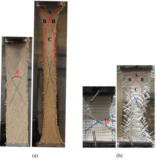
(29) Thèse de Shenglei Xiao, Université de Lille, 2019. Chapter Ⅰ. State of The Art. friction between crossing yarns, so that the in-plane force initially is very small compared to the known in-plane tension values. And then, the in-plane shearing force gradually increases due to contact and laterally compression of intersection yarns. When all the yarns are in contact and compressed, the force increases rapidly, and a critical locking angle is reached [111–113]. There are two principle methods to determine the shear properties of textile reinforcements, bias-extension test and picture frame test, as shown in Fig. 1.10. Such two methods are initially designed since the 1960s and then developed for investigating the inplane shearing properties of woven fabrics [114–117]. The bias-extension test consists of a tensile test on the woven fabric that the warp and weft yarns directions are orientated initially at 45° to the direction of applied tension. The description of bias-extension with respect to its specifications, the geometry of rectangular specimen and different shearing zones, are made by Wang et al. in 1998 [118]. If the shearing zones in the fabric can be seen during the test, the size of the fabrics (reinforcements) must satisfy the certain geometrical conditions, as shown in Fig. 1.10(a). In general, when the length of specimen, L, is more than twice its width, W, and assuming no inextensibility and slippage of yarns, there are three zones distinguished theoretically during the test that the zone A remains undeformed, a pure shearing zone in the centre of fabric (zone C), and a half of shearing zone B near zone A [56,119–122]. It is assumed that the in-plane shearing is constant in each zone. A picture frame test is a hinged frame with four rigid bars with equal length as shown in Fig. 1.10(b). The tension is applied across diagonally opposite corners of the picture frame rig, causing the picture frame to move from an initially square geometry into a lozenge. The specimen within the picture frame is theoretically subjected to a pure and constant in-plane shearing [114,123,124]. Contrasted with such two tests, it is suggested that the bias-extension test lies the advantage in terms of accuracy and convenient, especially for exploring the thermo-characteristics. Consequently, the research on exploring the in-plane shearing based on bias-extension is relatively extensive. Although the other experimental tests have been proposed that a rectangular fabric specimen is clamped on two opposite edges, prescribe an in-plane shear deformation to the woven fabric [112,115], the tests are close to picture frame [125].. 17 © 2019 Tous droits réservés.. lilliad.univ-lille.fr.
(30) Thèse de Shenglei Xiao, Université de Lille, 2019. Chapter Ⅰ. State of The Art. (a). (b). Fig. 1.10. Two principle methods to determine in-plane shearing behaviours of woven fabric: (a) Bias-extension test; (b) Picture frame test [119,126]. Based on the assumptions including no slippage, neglected bending stiffness and inextensibility of yarns, the characteristics in in-plane shearing need to be specified on the kinematic correlation among the in-plane shear angle, shear stress, force and extension of fabric. Thus, the variation of in-plane shearing angle based on the shear load and force has been explored gradually [119,127] and can be directly obtained by optical analysis [128]. However, only explaining the variation of in-plane shearing angle is not enough to characterize the property of in-plane shearing. The shearing force to determine the in-plane shearing angle also needs to be confirmed at least concerning the geometry of specimen [126,129–131]. The shear load to the overall load of test machine were introduced in [114,126]. In addition, the shear moment was studied through the formulation of finite elements [128,132,133], completing the property of in-plane shearing. Other models based on the energetic approach were proposed to clearly specify the characteristics of shearing zones [134]. As the discussion above, the in-plane sharing behaviours are normally determined by dry composite reinforcements. However, for thermoset or thermoplastic prepregs, the mechanical behaviours are significantly different from that of dry textile reinforcements under the temperature variation, which is specially called as thermo-mechanical characterisations, depending on the state of the resin that could substantially modify the properties. In the case of thermoset prepregs, the performing temperature in the test is lower than curing temperature, but the in-plane shearing tests are performed at the temperature slightly over melting point of resin. According to properties of bias-extension and picture frame tests, the bias-extension is 18 © 2019 Tous droits réservés.. lilliad.univ-lille.fr.
(31) Thèse de Shenglei Xiao, Université de Lille, 2019. Chapter Ⅰ. State of The Art. relatively more adaptable for investigating the in-plane shearing at high temperature [129,135]. The loads on the specimen measured for bias-extension tests at a temperature around the melting point (343°C) for a carbon satin/PEEK matrix prepreg suggests that the influence of temperature is strong. The in-plane shear stiffness is much larger at 320°C than at 360°C. Nevertheless, over 360°C, the shear stiffness does not decrease anymore [136]. Besides, the different speeds at various temperatures in the tests also have an impact on the strain rate [136,137], but they are less important than the influence of temperature, possibly due to in the constitutive model [134,138]. According to the researches review above, it can be induced that the exploring of mechanical behaviours recently is primarily focusing on the woven reinforcements, which has been saturated indeed. The braided reinforcements have not been gained enough attraction on mechanical behaviours. The variation of braiding angles, which is considered as one of special parameters distinguished from woven ones, increases the difficulty of mechanical analysis. Thus, the geometrical and mechanical models concerning the braiding angles compared to woven ones are proposed. For examples, a geometrical and micromechanical model was developed by Potluri and Manan [52] for non-orthogonal reinforcements. In this study, the parallel between braided and sheared woven fabrics is established. The increasing of nominal axial strain in function of the braiding angle during tensile tests was experimentally shown on biaxial braids by Harte and Fleck [139]. A predictive model on the mechanical behaviour of biaxial braided fabrics was compared to experimental results in Hristov et al. [140], but in this study, the initial braiding angle of samples is considered as constant. Significant differences (around 20%) between numerical results computed with mechanical model and those obtained experimentally were demonstrated by Dabiryan and Johari[141] on biaxial braids with high braiding angles. Specific materials, as auxetic, were also used in biaxial braided structures and mechanically characterized by Subramani et al.[142]. Rebelo et al. [143] not only investigated the influence of design parameters partly on selected properties of braided stents such as radial compression but also on the various required characteristics such as porosity and cover factor. But this study is limited to biaxial braids with only 16 yarn bobbins. Del Rosso et al [144] described the experimental identification of tensile behaviour of biaxial microbraids (number of yarns lower from 16) made of Kevlar or Dyneema. Their study showed that the braiding angle plays a fundamental role in determining the final properties of the dry microbraids. The higher the braiding angle, the higher the strain to failure. On the other hand, these authors showed that microbraids. 19 © 2019 Tous droits réservés.. lilliad.univ-lille.fr.
(32) Thèse de Shenglei Xiao, Université de Lille, 2019. Chapter Ⅰ. State of The Art. having smaller braid angles have a stiffer response after jamming occurred with respect to those having bigger bias angles. The understanding of the tensile behaviour of braided materials was also the subject of research by Rawal [99,145–147], using the developments of models compared with experimental results. Based on the discussion above, it is suggested that the mechanical behaviour of braided reinforcements cannot be deduced from the numerous studies dedicated to the behaviour of dry woven fabrics. In addition, it is still unclear whether the bias-extension test is adaptable for determination of in-plane shearing for braided fabrics since the geometrical conditions and the in-plane shearing characteristics under the condition of non-orthogonal fabrics are not clearly defined. In this case, the picture frame test is obviously no more adaptable because it would require the design and processing tested hinged frames for each braided angle, which is inconvenient and uneconomical. Furthermore, for triaxial fabrics, adding the yarns along axial direction could change totally mechanical behaviours, which need an in-depth study based on a variation of braiding angles. At last, in order to optimise the manufacturing process, especially for providing the appropriate temperature during forming process, the thermosmechanical behaviours of braided reinforcements should be also explored under temperature variation.. 1.3 The stage of preforming The reinforcements would be beforehand preformed to the desired shapes before resin injecting during manufacturing composites with complex shapes as shown in Fig. 1.11. This stage is defined as the preforming process, which is the first step of the phases in LCM. Mastering the preforming quality of reinforcements is significant because it would heavily influence the properties of final composites. However, the composite reinforcements preforming is a difficult stage including the complex deformability behaviours such as yarns sliding, in-plane shearing behaviour, intra-ply sliding and material draw-in, which are influenced by many process parameters such as the preforming load, the initial orientation of yarns, the properties of yarns and the shape of tools [148]. Hence, it is complicated to precisely characterise the deformability behaviours during preforming stage. Moreover, the preforming defects observed at different scales (mesoscopic and macroscopic scales), such as buckling, wrinkling, and misalignment [149–152], are heavily associated with preforming behaviours. These defects can bring negative influences on the resin impregnation, and critical changes of the in-plane and through-thickness permeability [148,153,154]. 20 © 2019 Tous droits réservés.. lilliad.univ-lille.fr.
(33) Thèse de Shenglei Xiao, Université de Lille, 2019. Chapter Ⅰ. State of The Art. Consequently, in order to produce the complex geometric composites without defects, it is important to acquire the deformability behaviours during the preforming process.. Wrinkling. (a). (b). (c). Fig. 1.11. Some typical preform shapes, (a) Hemisphere, (b) Square and (c) Tetrahedron At present stage, the researches on deformability behaviours associated with defects mainly focus on the relationship between preforming parameters and characteristics presented by different behaviours, and trying to figure out the inherent relation among them then optimizing the preforming process. Wrinkling is one of the most common preforming defects at macroscale, caused by the effects on in-plane shearing and bending [132,155,156]. The methods such as finite element and experimental analysis are utilized to find out the correlation between the processing parameters like blank-holder pressure and wrinkle [132,150,155], and finally to optimise the preforming stage [133,157,158]. But the preforming defects characterised at macroscale or mesoscale are more difficult to quantify, in particular for the complex shapes with high curvatures and large deformations [159,160]. The sliding of the network, which can be defined as inter-ply sliding in multilayers preforming or yarn sliding in monolayer preforming, is another preforming behaviour that probably has a negative influence on the preforming quality. The inter-ply sliding denoted by the relative movements of the plies induces the local wrinkles [161,162]. In contrast, the yarns sliding depending on the blank-holder pressure is experimentally defined in [148] and could lead to the buckles as shown in Fig. 1.12 (b). Gatouillat et al. presented numerically that excessive sliding between warp/weft yarns can lead to a loss of cohesion in the woven network [163]. In this case, the tow or yarn orientation cannot be controlled during the preforming and the local fibre density decreases. Consequently, a decrease in local fibre density can influence the resin impregnation and may lead to the resin-rich zone in final composite parts, the mechanical properties hence are impacted undesirably.. 21 © 2019 Tous droits réservés.. lilliad.univ-lille.fr.
(34) Thèse de Shenglei Xiao, Université de Lille, 2019. Chapter Ⅰ. State of The Art. (a). (b). Fig. 1.12. The performing defects: (a) Local wrinkles and buckles; (b) The amplification of buckles [161]. As same as discussion on mechanical behaviours of reinforcements, the preforming exploration in previous researches mainly concentrates on the woven fabrics, NCF(Noncrimp-Fabrics) or unidirectional prepreg laminates[155,164] with different punch shapes such as hemisphere [165–167], double-dome [158,168,169], eccentric cone [170], tetrahedral and square box [156,171–174]. The deformability behaviours show different magnitudes and profiles in such punched shapes. On the contrary, even though Jacquot et al. [175] compared the deformability behaviours of woven and biaxial braided fabrics manufactured from the same comingled flax/PA12 yarns on the hemispherical punch, there are relatively few research works dealing with the braided reinforcements preforming. Furthermore, as one of important parameters of braided reinforcements, the braiding angle could heavily impact the composites properties in terms of vibration behaviours, tensile strength and energy abortion [176–178]. Thus, it is reasonable to believe that deformability behaviours during preforming process would be varied by braiding angle selected. The optimization to avoid the certain preforming defects related to in-plane shearing behaviour such as wrinkling could be designed according to mechanism of deformability behaviours decided by braiding angle. However, such exploration on variation of deformability behaviours changed by braiding angle during preforming is still absence. In addition, the triaxial braided reinforcements with a specific structure possibly present the different deformability behaviours, compared to the classical biaxial textile fabrics (woven or biaxial braided fabrics). However, due to the lack of research of mechanical characters in deformability behaviours of biaxial fabrics, the difference between biaxial and triaxial fabrics in preforming process does not draw enough attention.. 22 © 2019 Tous droits réservés.. lilliad.univ-lille.fr.
(35) Thèse de Shenglei Xiao, Université de Lille, 2019. Chapter Ⅰ. State of The Art. 1.4 The composites machining by abrasive waterjet (AWJ) The FRPs possess the advantages for lightweight design but also bring challenges to machining process due to anisotropy and abrasive properties. After manufacturing but before assembly process, the FRPs machining is unavoidable in most cases, for instance, drilling or cutting, for the purpose of satisfying the requirements in assembly process. Due to contact between cutting tools and materials, traditional processing technique, which is most common method in FRPs machining by now, probably result in a heat-affect zone which could degrade the fibre or matrix, especially which has the low thermostability. Although the innovations in cutting tools or process could enhance machining quality to some extent, the balance between the efficiency, machining quality and the cost is still the problem that the manufacturing of automobile, aircraft, etc. should reasonably and carefully consider. The non-traditional processing techniques as laser or electric discharge machining are also unadaptable for FRPs machining considering the same problem of the heat-affect zone. Recently, abrasive waterjet (AWJ) processing technique, an emerging versatility and coolmachine method, has been gradually used in FRPs machining. AWJ uses high pressurized water mixed with abrasive particles through small diameter orifice nozzle to strike on and consequently remove materials by means of erosion mechanism. This processing technique could be theoretically fitted with almost all materials, especially for metal and glass which have been extensively studied during the past twenty years. Except for no heat-affect zone, AWJ also provides the advantages including minimal residual stresses and surface hardening on the materials due to small cutting force. Besides, the recyclable abrasives and water further reduce the cost and almost without pollution, attracting more and more attention from the machining field. In recent years, AWJ has been extensively applied into many processing methods such as cutting, turning, drilling and milling. Among them, the cutting processing is still the most widely accepted even though cutting performance including kerf taper or surface quality is undesired in certain cases. Due to the advantages discussed above, AWJ cutting process has been widely studied by many researchers from many aspects. In early investigations of AWJ cutting, Hashish[179] proposed that the two cutting zones exist in processing ductile materials under AWJ based on the erosion mechanisms that were proposed by Finnie and Bitter [180–182]. The cutting zones in kerf wall are easily distinguished because of impacting angle at different angles as shown in Fig. 1.13(a). The upper zone of kerf wall is characterized by impacting at a shallow angle,. 23 © 2019 Tous droits réservés.. lilliad.univ-lille.fr.
Figure


+7


Documents relatifs