A Simplified Rotational Spring Model for Mitral Valve Dynamics
Texte intégral
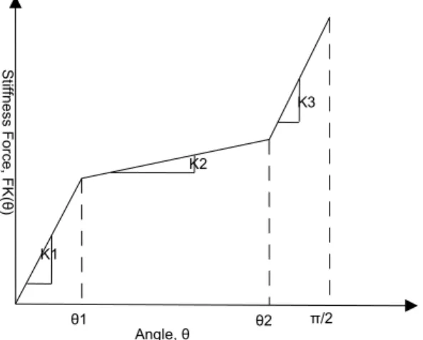
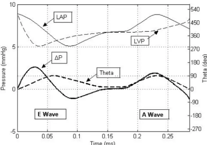
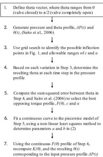
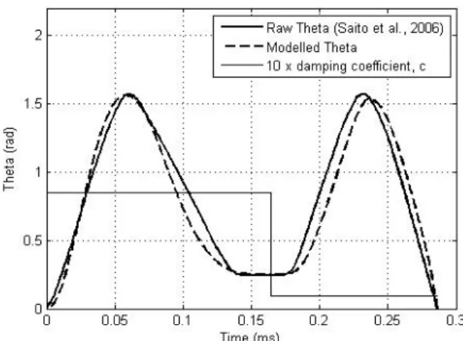
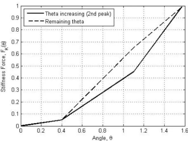
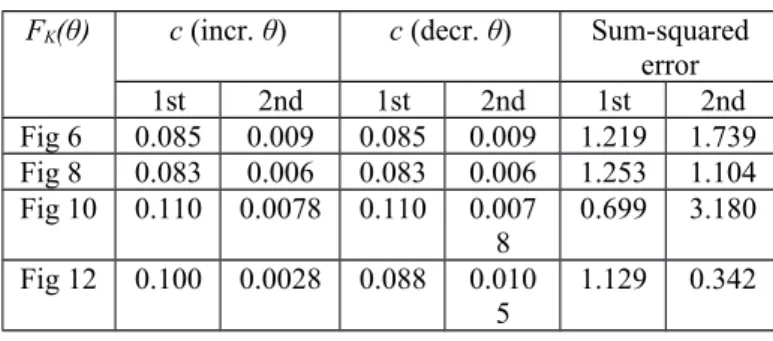
Figure

Documents relatifs
1 - اهتايح لحارم للاخ ةطسوتلماو ةريغصلا تاسسؤملل ةيلالما تاجايتحالا ةلحرم لكل ةطسوتلماو ةريغصلا ةسسؤلما ةايح لحارم نم اهب ةصاخلا اهتاجايتحاو اهتابلطتم ريغتل ارظن
Semi-quantitative RT–PCR performed on RNA isolated from these cells demonstrated that rapamycin treatment reduced transcript levels from all reporter plasmids equally, indicating
Ce qui est opératif, dans toute formation, est d'adopter le point de vue du sujet, et en didactique, « adopter le point de vue du Sujet, c'est tomber tôt ou tard sur deux notions
The variations include: whether the edge set of the graph re- mains fixed or changes over time; whether the graph is undirected or directed; whether the dynamics is continuous
Using the (NUV−r) versus (r−K) rest-frame colour diagram to classify star-forming and quiescent galaxies in our sample, we measured the evolution of the SMFs of the two populations
Des aubes bleues piquetées d'or Un jour se lève à vivre encore Et la brise vient caresser ta peau. Au ciel traînent quelques étoiles La lune se couche sur
These major principles needed to be used not only for the visual design of the website, but also for the Information Architecture design in terms of navigation and structure. This
(1) Cette estimation d'emploi, réalisée par l'Insee à partir des résultats de l'enquête trimestrielle ACEMO et à partir des déclarations mensuelles des entreprises de
