ROBUSTNESS OF BUILDING STRUCTURES
Recent developments and adopted strategyJean-François Demonceau, Ludivine Comeliauand Jean-Pierre Jaspart University of Liège, ArGEnCo department, Belgium
ABSTRACT
Recent events such as natural catastrophes or terrorism attacks have highlighted the necessity to ensure the structural integrity of buildings under an exceptional event. According to the Eurocodes and some different other national design codes, the structural integrity of civil engineering structures should be ensured through appropriate measures but, in most cases, no precise practical guidelines on how to achieve this goal are provided.
At the University of Liège, the robustness of building frames is investigated following the so-called “alternative load path method”, with the final objective to propose design requirements to mitigate the risk of progressive collapse considering the conventional scenario “loss of a column” further to an unspecified event. In particular, a complete analytical procedure has been developed for the verification of the robustness of steel or composite plane frames. For sake of simplicity, these first works have been based on the assumption that the dynamic effects linked to the column loss were limited and could therefore be neglected. More recently, complementary works have been carried out with the objective to address the dynamic effects. Besides, the extension of the static procedure to actual 3D frames is under investigation in Liège. The present paper gives a global overview of the ongoing researches in the field of robustness at the University of Liège and, in particular, the global strategy aiming at deriving design requirements is detailed.
Keywords: robustness, column loss, alternative load path, static and dynamic behaviour, analytical model
1 ADOPTED STRATEGY
The investigations performed at the University of Liège in the field of “robustness of structures” are mainly dedicated to the exceptional scenario “loss of a column” in a steel or steel-concrete composite building structure. The main objective of the conducted investigations is to derive guidelines aiming at ensuring an appropriate behaviour of the structure for the considered scenario. To achieve this goal, simplified analytical procedures are developed to predict the response of the structure further to a column loss; this allows to clearly identify how each structural parameter may influence the structural behaviour. The present section describes the global strategy adopted at the University of Liège.
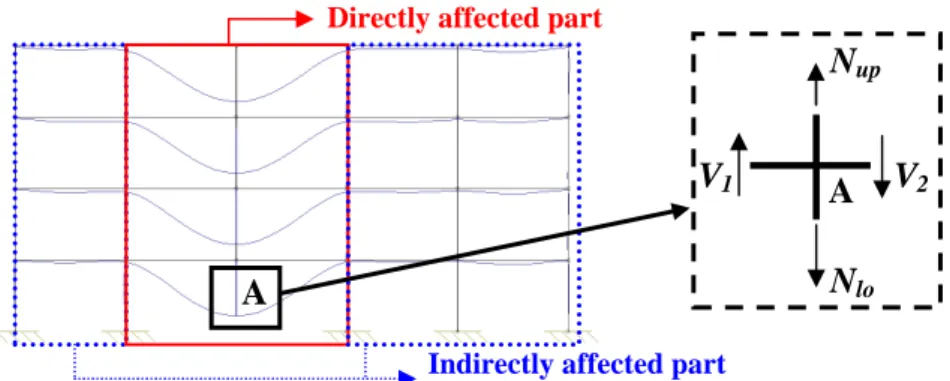
The loss of a column can be associated to different types of exceptional events: explosion, impact of a vehicle, fire… Under many of these exceptional actions, dynamic effects may play an important role. However, let’s first assume that the column loss does not induce dynamic effects; so, the investigations of the structural response may be founded on static approaches. A building structure losing a column can be divided in two main parts, as illustrated in Fig. 1: the directly affected part which represents the part of the building which is directly affected by the column loss, i.e. the beams, the columns and the beam-to-column joints which are just above the failing column; and the indirectly affected part which consists of the rest of the structure. The indirectly affected part is affected by the loads developing within the directly affected part and also influences the development of these loads.
If a cut is realised in the structure at the top of the failing column (see Fig. 1), different internal forces in the vertical direction are identified: (i) the shear loads V1 and V2 at the extremities closed
axial load Nlo in the failing column. The objective of the studies performed at the University of
Liège is to be able to predict the evolution of the vertical displacement of point “A”
∆
A according toNlo, with due account to the eventual membrane forces developing in the structure, in order to know
the requested ductility of the different structural members and to check the resistance of the indirectly affected part loaded by additional loads coming from the directly affected part.
.
Fig. 1.Representation of a frame losing a column and main definitions
In Fig. 2, the curve representing the static evolution of the vertical displacement
∆
A according to thenormal load Nlo in the failing column (see Fig. 1) is illustrated:
- From point (1) to (2) (Phase 1), the design loads are progressively applied, i.e the “conventional” loading is applied to the structure; so, Nlo progressively decreases (Nlo becomes
negative as the column “AB” is subjected to compression) while
∆
A remains approximatelyequal to 0 during this phase. It is assumed that no yielding appears in the investigated frame during this phase, i.e. the frame remains fully elastic.
- From point (2) to (5), the column is progressively removed. Indeed, from point (2), the compression in column “AB” Nlo decreases until it reaches a value equal to 0 at point (5) where
the column is considered as fully destroyed. So, in this zone, the absolute value of Nlo
progressively decreases while the value of
∆
A increases. This part of the graph is divided in twophases as represented in Fig. 2:
o From point (2) to (4) (Phase 2): during this phase, the directly affected part passes from a fully elastic behaviour (from point (2) to (3)) to a global plastic mechanism. At point (3), the first plastic hinges appear in the directly affected part.
o From point (4) to (5) (Phase 3): during this phase, high deformations of the directly affected part are observed and second order effects play an important role. In particular, significant catenary actions develop in the bottom beams of the directly affected part.
Phase 3 Ph ase 2 P h a s e 1 ∆ N (1) (2) (4) (5) (3) lo lo.design N
Fig. 2. Evolution of Nlo according to the vertical displacement at the top of the loss column
It is only possible to reach point (5) if:
Indirectly affected part Directly affected part
V1 V2 Nup Nlo A A A
− the loads which are reported from the directly affected part to the indirectly affected part do not induce the collapse of elements in the latter (for instance, buckling of the columns or formation of a global plastic mechanism in the indirectly affected part);
− the different structural elements have a sufficient ductility to reach the vertical displacement corresponding to point (5).
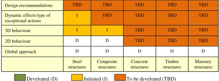
This global approach was first developed for steel and composite structures but may be applied to other typologies of structures, as given in Table 1. In a first step, simplified analytical methods were developed to predict the response of 2D steel and composite frames further to the loss of a column with no dynamic effects; the latter are summarised in section 2. Then, funded on this first step, investigations were initiated to take the 3D behaviour and the dynamic effects into account; the latter are respectively introduced in Section 3 and Section 4. The objective at the end is to have Table 1 fully completed with “D” which would mean that design recommendations have been derived for most typologies of structures and are founded on the same global approach.
Table 1. Steps to be crossed to derive design recommendations
Design recommendations TBD TBD TBD TBD TBD Dynamic effects/type of exceptional actions I TBD TBD TBD TBD 3D behaviour I I TBD TBD TBD 2D behaviour D D TBD TBD TBD Global approach D D D D D Steel structures Composite structures Concrete structures Timber structures Masonry structures
2 STATIC BEHAVIOUR OF 2D FRAMES FURTHER TO A COLUMN LOSS
In two complementary PhD thesis ([1] and [2]), analytical procedures have been derived to predict the response of steel and composite 2D frames during Phase 2 and Phase 3 (see Fig. 1). The performed developments are summarised in [3] and [4].
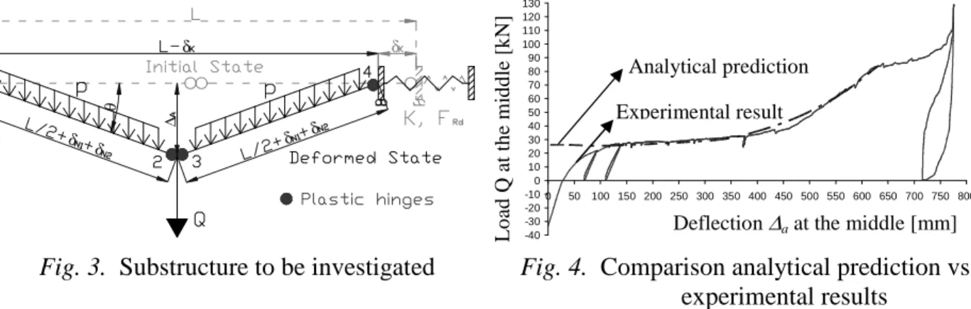
In particular, it was shown in [1], through numerical investigations, that it is possible to extract a simplified substructure (see Fig. 3) able to reproduce the global response of the frame during Phase 3. Accordingly, a simplified analytical method based on a rigid-plastic analysis has been developed to predict the response of the so-defined substructure. Also, as the deformations of the substructure are significant and influence its response, a second-order analysis has been conducted.
The parameters taken into account in the developed procedure are presented in Fig.3:
− p is the (constant) uniformly distributed load applied on the storey modelled by the simplified
substructure and the concentrated load Q simulates the column loss (= Nlo – Nup (see Fig. 1)
with Nup assumed as constant and equal to Nup at point 4 (see Fig. 2) as demonstrated in [2]);
− L is the total initial length of the simplified substructure;
−
∆
Q is the vertical displacement at the concentrated load application point;−
δ
K is the deformation of the horizontal spring simulating the lateral restraint provided by theindirectly affected part while
δ
N1 andδ
N2 are the plastic elongations at each plastic hinge; −θ
is the rotation at the plastic hinges at the beam extremities.In addition, the axial and bending resistances at the plastic hinges NRd1 and MRd1 for plastic hinges 1
and 4 and NRd2 and MRd2 for plastic hinges 2 and 3 have also to be taken into account (it is assumed
that the two plastic hinges 1 and 4 and the two plastic hinges 2 and 3 (see Fig. 3) have respectively
the same resistance curve for M-N interaction).
In order to be able to predict the response of the simplified substructure, the parameters K and FRd
have to be known; these parameters depend of the properties of the indirectly affected part (see Fig.
1). In [2], analytical procedures have been defined to predict these characteristics.
To validate the developed analytical method, the results obtained with the latter have been compared to the results of an experimental test on a substructure performed at the University of Liège ([1] and [5]) as illustrated in Fig. 4. In this figure, it is observed that a very good agreement is obtained between the analytical prediction and the experimental results, which validates the developed method. More details about the developed method are available in [1].
δ δ δ δ δ δ ∆ θ -40 -30 -20 -10 0 10 20 30 40 50 60 70 80 90 100 110 120 130 0 50 100 150 200 250 300 350 400 450 500 550 600 650 700 750 800
Deflection at the middle [mm]
L o a d a t th e j a c k [ k N ] Experimental result Analytical prediction
Fig. 3. Substructure to be investigated Fig. 4. Comparison analytical prediction vs.
experimental results
3 STATIC BEHAVIOUR OF 3D STRUCTURES FURTHER TO A COLUMN LOSS
In a master thesis [6], the behaviour of 3D structures made of steel beams and columns has been investigated. Two different structures have been considered. The dimensions and the elements of these structures are exactly the same (see Fig. 5) except for the joint properties at the extremities of the secondary beams: Structure 1, the secondary beam extremities are fully pinned and Structure 2, these extremities are fully rigid.
For both cases, the column which is considered to be lost is the column exactly at the centre, as illustrated in Fig. 5 (column “BX”).
For each structure, a simplified substructure (see Fig. 6) has been defined and extracted from the full 3D structure with the objective to check the possibility of this substructure to simulate with a sufficient accuracy the behaviour of the real structure when significant membrane forces develop. The procedure followed for the definition of the substructure is the same as the one used for 2D frames (see Section 2 and [1]). This substructure is made of (i) four beams (two primary beams and two secondary beams) which are connected at the top of the failing column in the floor just above the failing column and (ii) the joints at the extremities of these beams.
The influence of the rest of the structure (i.e. the part which is not directly affected by the column loss) is reflected by horizontal springs at the extremities of the so-defined substructure (see Fig. 6), with appropriate stiffness (Kx and Kz).
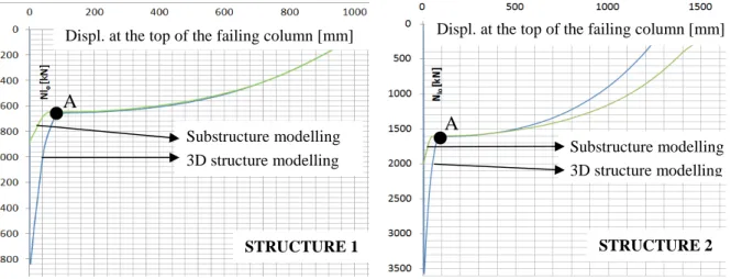
In Figure 7, a comparison between the predictions obtained (i) through a numerical simulation of the global 3D structure losing a column and (ii) through a numerical simulation of the so-defined substructure is given for the two considered structures. The graphs given in Fig. 7 represent the evolution of the axial load Nlo in the failing column according to the vertical displacement at the top
of this column. As the objective with the substructure is to predict the behaviour of the structure when significant membrane forces develop in the system, the predictions can only be compared from point A (see Fig. 7), i.e. when a plastic mechanism is formed in the structure and significant vertical displacements are reached. In Fig. 7, it can be observed that a very good agreement is obtained for Structure 1 while it is not the case for Structure 2. This observation can be explained as follows. The loss of the column is reflected in the substructure modelling through the application of a concentrated load Q (see Figure 6). In practice, this load Q is equal to the difference between Nlo
and Nup (see Fig. 1). For some structures, it was demonstrated through a parametrical study [2] that,
when significant membrane forces are developing in the directly affected beams, the value of Nup
Experimental result Analytical prediction
Deflection ∆a at the middle [mm]
L o ad Q a t th e m id d le [ k N ]
can be assumed as a constant. Accordingly, the variation of Q vs. the deformation of the substructure reflects the variation of Nlo in the global structure. It is the reason why, for 2D
structure, it was possible to reflect the actual behaviour of the 2D frame with the substructure. For Structure 1, Nup also appeared to remain approximately constant after the formation of the plastic
mechanism and thus the substructure approach is valid. But for Structure 2, it was observed that the value of Nup cannot be assumed as a constant and so, the variation of Q according to the vertical
displacement in the substructure modelling does not reflect the evolution of Nlo in the 3D structure.
The fact that Nup is no more constant when significant membrane forces are developing is linked to
the fact that a redistribution of forces takes place between the storeys located above the lost column; this aspect, which has to be explicitly considered in the model, has not been analytically characterised yet but is currently investigated. If the variation of the normal force in the column just above the failing one is introduced in the substructure model, it may be seen that the results are in good agreement with those obtained from the study of the actual full 3D structure.
Fig. 5. Investigated 3D structure
Fig. 6. Substructure extracted from the 3D structure
Fig. 7. Comparisons between the results obtained through numerical simulations (i) of the 3D
structure and (ii) of the substructure Primary beam
Secondary beam
Displ. at the top of the failing column [mm] Displ. at the top of the failing column [mm]
Substructure modelling
3D structure modelling Substructure modelling 3D structure modelling A
A
It is also demonstrated in [6] that the analytical method initially developed for 2D frames [1] and able to predict the response of the “2D” substructure can be easily adapted to predict the response of the “3D” substructure defined in Fig. 6. Accordingly, when a method will be available to predict the influence of the restraint provided by the upper storeys on the normal load in the column just above the failing one, it will be possible to predict analytically the behaviour of the global 3D structure through the substructure modelling.
4 DYNAMIC BEHAVIOUR OF 2D FRAMES FURTHER TO A COLUMN LOSS
In [7] (see also [8]), the dynamic behaviour of 2D steel frames further to a column loss has been investigated. In particular, a simplified model has been developed to predict the dynamic behaviour of the substructure defined in Section 2. No details about the proposed procedure are given in the present paper; this procedure is applied to an example in another paper reported in the Eurosteel 2011 conference proceeding [9].
5 CONCLUSIONS
At the University of Liège, the exceptional scenario “loss of a column” in a building structure has been under investigation for a few years with the final objective to propose design requirements to ensure an appropriate robustness of structures under the considered scenario.
The present paper gives a global overview of the adopted strategy to deal with this scenario, of the achievements in this field so far and of the ongoing research activities. In particular, simplified analytical methods have been developed to predict the static response of 2D steel and composite frames further to a column loss. Investigations are presently in progress to extend these methods to 3D structures. Besides, the dynamic behaviour of 2D structures has been investigated and a procedure has been developed to predict the dynamic response of a simplified substructure. The dynamic behaviour of structures further to a column loss is still under investigation at the University of Liège to improve the model and to adapt it at the end to 3D structures.
REFERENCES
[1] Demonceau, JF, “Steel and composite building frames: sway response under conventional loading and development of membrane effects in beams further to an exceptional action”, PhD thesis presented at
Liège University, 2008 (freely downloadable at http://orbi.ulg.ac.be/handle/2268/2740).
[2] Luu, H.N.N., “Structural response of steel and composite building frames further to an impact leading to the loss of a column”, PhD thesis presented at Liège University, 2008 (freely downloadable at http://bictel.ulg.ac.be/ETD-db/collection/available/ULgetd-01212009-095305/).
[3] Demonceau, JF, Jaspart, JP, “Development of membranar effects in frame beams: experimental and analytical investigations”, EUROSTEEL 2008 “5th International conference on Steel and Composite
Structures”, pp. 1743-148, 2008.
[4] Luu, HNN, Demonceau, JF, Jaspart, JP, “Global structural behaviour of a building frame further to its partial destruction by column loss”, EUROSTEEL 2008 “5th International conference on Steel and
Composite Structures”, pp. 1749-1754, 2008.
[5] Demonceau, JF, Jaspart, JP, “Experimental test simulating a column loss in a composite frame”,
International Journal of Advanced Steel Construction (IJASC), Volume 6, Number 3, pp. 891-913.
[6] Lemaire, F, “Study of the 3D behaviour of steel and composite structures further to a column loss (in French)”, Master thesis presented at Liège University, 2010.
[7] Comeliau, L, “Effects of the dynamic behaviour of steel structures further to a column loss (in French)”.
Master thesis presented at Liège University, 2009 (freely downloadable at
http://hdl.handle.net/2268/32284).
[8] Comeliau, L, Demonceau, JF, and Jaspart, JP, “Robustness of steel and composite buildings under impact loading”, Proceedings of SDSS’ Rio 2010 International Colloquium – Stability and Ductility of
Steel Structures, Vol. 1, pp. 393-400, Rio de Janeiro, 2010.
[9] Comeliau, L, Demonceau, JF, and Jaspart, JP, “Robustness of building frames further to a column loss - Substructure approach with account of dynamic effects”, EUROSTEEL 2011, 2011.
Corresponding author: Demonceau Jean-François Assistant Professor
Liège University, ArGEnCo Department, MS²F Division Chemin des Chevreuils, 1 B52/3, 4000 Liège, Belgium Tél: +32-(0)4-3669358 - Fax: +32-(0)4-3669192