Science Arts & Métiers (SAM)
is an open access repository that collects the work of Arts et Métiers Institute of
Technology researchers and makes it freely available over the web where possible.
This is an author-deposited version published in: https://sam.ensam.eu Handle ID: .http://hdl.handle.net/10985/11760
To cite this version :
Mariana STAIA, A TROCELIS, Amel ZAIRI, M SUAREZ, Eli-Saul PUCHI-CABRERA, Alain IOST, Alex MONTAGNE - Surface Modification Technologies - In: Surface Modification Technologies, Italie, 2016-07-01 - SMT30 - 2016
Any correspondence concerning this service should be sent to the repository Administrator : [email protected]
XXX International Conference on
Surface Modification Technologies (SMT30)
29TH JUNE - 1ST JULY, 2016, MILAN, ITALY
_____________________________ * Corresponding author. Tel.: 0033623582825
E-mail address: [email protected]
ASSESSMENT OF THE MECHANICAL AND TRIBOLOGICAL
PERFORMANCE OF A ZrN PVD COATING
M. H. Staia
a,b*, A. Trocelis
a, A. Zairi
b, M. Suarez
a, E. S. Puchi-Cabrera
a,c,
A. Iost
b, A. Montagne
baEscuela de Ingeniería Metalúrgica y Ciencia de los Materiales, Facultad de Ingeniería, Universidad Central de
Venezuela
bArts et Métiers ParisTech, MSMP, Centre de Lille, 8, Boulevard Louis XIV, 59000 Lille Cedex, France cUniversité Lille Nord de France, UVHC, LAMIH UMR CNRS 8201, F-59313 Valenciennes, France
_________________________________________________________________________________________________________________________________
Abstract
The present work has been conducted in order to assess the mechanical and tribological performance of a ZrN coating deposited onto a H13 steel substrate by means of a closed field unbalanced magnetron-sputtering ion-plating (CFUMSIP) process. The hardness and elastic modulus of the coated system have been determined by means of nanoindentation techniques. Dry and wet sliding wear tests, employing a tribometer under a ball-on-disc configuration, were carried out making use of an alumina ball as counterpart, with an applied normal load of 2 N at a constant speed of 5 cm/s. For the wet wear tests, a 3.5 wt% NaCl solution was used. The resulting wear scars were analyzed by means of both SEM and optical profilometry techniques. It has been determined that, during testing under the corrosive solution, the coating experiences a severe abrasive wear mechanism, due to the combined action of the alumina ball, the hard “debris” and the phenomenon of crevice corrosion. On the other hand, it has also been shown that the coated system is able to increase the wear resistance of the substrate by more than one order of magnitude, if the wear tests are carried out in air under the same conditions.
Keywords: sliding wear; corrosive solution; nanoindentation; ZrN coatings; PVD
_______________________________________________________________________________________________________________________________
1. Introduction
ZrN belongs to the nitride coatings family that has demonstrated the possibility of being used in many applications. Among the interesting properties exhibited by zirconium nitrides are their high hardness and wear resistance, low friction coefficient and high corrosion resistance that are of great interest to different industries in applications such as diffusion barriers in integrated circuits, decorative coatings for jewelry, production of cryogenic thermometers, for power reactors in the aerospace industry and in the cutting tools industry, among others. The main properties of these coatings, their use, as well as the processes employed for their production have been recently reviewed by Ningshen et al. (2013).
ZrN coatings have also been considered as important candidates for the semiconductor IC packaging molding dies protection. It has been shown that CrN, ZrN, and TiAlCrN produced by closed field unbalanced magnetron sputter ion plating (CFUBMSIP) could substitute the hard chromium coating, considering its excellent anti-adhesion properties (Sun et al., 2006). However, additional important issues that arise between the epoxy molding compound and the encapsulation molds are those related to the mold releasing problems and the tribological performance of these coatings (Lina et al., 2006).
Different wear studies at room temperature of ZrN coatings deposited by reactive unbalanced magnetron sputtering against different counterparts such as steel (Fragiel et al., 2008; Valerini et al., 2013), WC-Co (Auger et al., 2007), alumina (Lopez and Staia, 2008) and silicon nitride balls (Singh et al., 2012) have been reported in the literature. Nevertheless, the behavior against the steel ball as counterpart, indicates an adequate performance as long as the ZrN coating has a good adhesion to the substrate, achieved either by optimizing the deposition parameters or by using buffer thin films such as Zr between the coating and the substrate in order to improve it (Chou et al., 2003, Jianxin et al., 2008). It is well known that mass transfer from the steel ball to the coating and back will take place as a consequence of the differences between the hardness values of the mating surfaces. In the case of counterparts exhibiting similar or higher hardness than ZrN coatings, an important abrasion process will occur and the wear process will be enhanced due to the presence of debris.
Few tribocorrosion studies have also been carried out on ZrN coated systems. Ferreira et al., (2006) investigated the behavior of ZrOxNy and ZrN coatings, of 3.2 to 6.2 m thickness deposited on an AISI M2 steel
by magnetron sputtering. Wear testing was carried out under potentiostatic control in an artificial sweat solution. The authors reported that both the amount of material removed and the time needed for the film to be removed from the contact zone depend on the coating thickness. Moreover, it was determined that the dissolution of the substrate governed the degradation of the coated system.
In the present communication, the main results concerning the mechanical and morphological characterization of a ZrN coating produced by a CFUBMSIP process are reported. Buffer films, such as Mo and MoN, were used to improve the coating adhesion to the steel substrate. Wear tests were performed both in air and under the simultaneous action of mechanical wear and a chemical aggressive environment. A correlation of the wear performance of the ZrN coating in both environments with the mechanical, morphological and coated system architecture characteristics is also presented.
2. Experimental
2.1 Materials and coatings deposition
The CFUBMSIP deposition process has been used to produce a ZrN coating of approximately 1.3 m in thickness. The deposition process was carried out industrially at Teer Coatings Ltd., Worcestershire, England. H13 steel substrate samples, of 3 cm diameter, were prepared by using standard metallographic techniques and then cleaned ultrasonically in methanol. Subsequently, they were cleaned in situ prior to the deposition process by means of argon sputter etching. Two metallic targets of Mo and Zr, respectively were employed. The Mo target was used first and allowed the deposition of a very thin metallic Mo layer, aimed at ensuring a proper adhesion between the ZrN coating and the H13 steel substrate. By allowing an Ar-N2 gas mixture inside the
reactor, a thin film of 0.2 m of a molybdenum nitride phase was subsequently formed, before ramping in Zr to form the main ZrN layer of 1.1 m.
2.2 Coating characterization.
Figs. 1a and 1b illustrate the SEM micrographs of the coating surface and its cross section, respectively after being fractured by impact. Fig. 1b shows the cross section of the fractured sample with a morphology that corresponds to the boundary between zone 1 and the T zone of Thornton’s structure zone classification. It is characterized by the presence of dense and not very well defined fibrous crystals, with a small amount of voids between them, typical of PVD processes of relatively low adatom mobilities (Thornton, 1986).
Fig.1. ZrN coating SEM micrographs: a. coating surface morphology; b. coating fractured cross section (22000X)
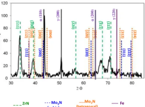
The coating structural characterization was carried out by performing X-ray analysis with a Siemens D5000 diffractometer employing Co-Kα radiation (λ=1.78897), a 0.02° scanning step size, 4 second of count time per step and a 2ϴ angle range between 30° and 90°. The XRD pattern is presented in Fig. 2, where the diffraction lines correspond to ZrN (cubic structure, ICDD PDF#35-0753). It could be observed that the ZrN film has a (111) preferred orientation. The small peaks could be attributed to a Mo2N compound, since its
thickness is very small (200 nm). In this pattern, both tetragonal and cubic structures were indicated (ICDD PDF#24-0768 and ICDD PDF#25-1366, respectively). However, Jauberteau et al. (2006) have already pointed out that it is not easy to differentiate between -Mo2N and -Mo2N by conventional X-ray diffraction techniques.
Therefore, the precise structure of molybdenum nitrides cannot be unambiguously determined. Additionally, characteristics peaks of Fe () and Fe () are also indicated in the pattern.
The surface roughness of the coating was measured by means of optical profilometry, using a Veeco Wyko NT9300 profilometer. The results indicated a smooth appearance with a roughness of 0.03 m. The hardness and elastic modulus of the ZrN coating were determined by means of nanoindentation tests using a MTS XP Nano Indenter under a continuous stiffness measurement mode and equipped with a Berkovich indenter. Prior to indentation, the indenter tip calibration was carried out on fused silica. 25 indentations were
conducted on three different samples and the elastic modulus, E, and hardness, H, were recorded continuously versus the indentation depth, h, up to 2000 nm, at a constant indentation rate of 0.05 s-1. As far as the
computation of the hardness and elastic modulus is concern, the coated system is considered to be composed of a 0.2 m layer of molybdenum nitride and a 1.1 m layer of zirconium nitride.
_ _ _ ZrN - - - Mo2N (cubic) --- Fe ...Mo2N (tetragonal) Θ (1 11 ) (1 12 ) (1 03 ) (2 00 ) (1 1 1 ) (2 0 0 ) (2 0 0 ) (2 2 0 ) (0 0 4 ) (2 20 ) (2 2 0 ) (2 0 4 ) (3 1 1 ) (2 22 ) (3 1 2 ) (3 11 ) (2 2 2 ) (2 2 4 ) (1 10) (200 ) (220) (200 )
Fig.2. XRD pattern of the ZrN coating
2.3. Tribological characterization
The tribological characterization was carried out by means of sliding wear tests, employing a tribometer under a ball-on-disc configuration. The samples were immersed in a special device able to hold the aggressive solution. The wear tests were carried out in the presence of a 3.5 wt% NaCl solution with a pH value = 6.2. In each test, 25 ± 1 ml of the solution was used and the tests were performed by triplicate. For this purpose, a 6 mm diameter alumina ball was used as counterpart, with an applied normal load of 2 N, a sliding distance of 200 m and a constant speed of 5 cm/s.
Prior to each test, the samples were ultrasonically cleaned and dried in air. The worn samples morphologies were evaluated by means of SEM techniques. Optical profilometry was employed to assess the topography of the wear scars and to compute their cross section areas, which are needed to determine the wear volumes.
3. Results
3.1. Mechanical properties
Figures 3(a) and 3(b) illustrate the change both in hardness (H) and elastic modulus (E) with indentation depth (), for the coated system under study. The experimental data include approximately eleven thousand points. In the case of the hardness curve, the data is distributed in a wide scatter band, particularly when 350 nm. In this range of values, H can be considered to be constant, with a magnitude of approximately 25 GPa. As increases, H decreases with the trend of achieving the substrate hardness, of approximately 6 GPa. As can be observed in Figure 1, all the data points for which < 100 nm were disregarded, as indicated by the calibration procedure of the Berkovich indenter that was performed with the fused silica standard.
The H versus curve that was determined experimentally for this bi-layer coating can be readily described by means of the general methodology proposed by Puchi-Cabrera et al. (2015a) for the analysis of the hardness response of multilayer coated systems. Such analytical procedure is founded on the different models previously proposed for the description of the H versus curve for those coated systems which involve monolayer coatings.
Fig. 3. (a) Change in the hardness of the coated system with indentation depth; (b) Change in the elastic modulus of the coated system with indentation depth
Particularly, if the model advanced by Puchi-Cabrera [2002, 2004] for monolayer coatings is extended to the analysis of this bi-layer system, the description of the experimental data would encompass the determination of the intrinsic hardness of both the ZrN and Mo2N layers (HZrN and HMo2N, respectively), as well
as the coating thickness fractions from which the Mo2N film or substrate would start to contribute to the
composite hardness. The different equations that describe the computational instrumentation of this kind of analysis have been reported elsewhere [Puchi-Cabrera et al., 2015a; Staia et al., 2016]. Accordingly, HZrN = 24.2
GPa and HMo2N = 18.2, whereas HH13 = 6.1 GPa. It is important to point out that in this indentation analysis, no
indentation size effect (ISE) either of the films or steel substrate was considered.
Similar hardness values, varying between 23 to 25.1 GPa, for ZrN coatings deposited by ion plating on 316 stainless steel have been reported by Huang et al., (2005), when studying the variation of thickness and its effect on their structure and properties. However, changes in the applied bias, in the range of 0 to -120, during the reactively DC magnetron sputtering process employed, had shown a major influence on the hardness, whose value could change from 22 to 33 GPa, as determined by Pilloud et al. (2003). On the other hand, the relatively lower hardness value determined for the Mo2N, HMo2N = 18.2, points out the presence of -Mo2N in our system
rather than the -Mo2N, as indicated by the hardness value of 12 GPa reported by Jauberteau et al., (2015) for a
-Mo2N film. Figure 3(a) illustrates the description provided by the model, together with the mean curve
corresponding to the experimental data. It can be clearly observed that the model is able to describe quite accurately the change in hardness with indentation depth by considering the above indicated hardness values, as well as the correct sequence in which both films and substrate contribute to the composite hardness.
The computed values of the corresponding volume fractions of the different layers, which encompass the coated system, indicate that the ZrN film determines entirely the hardness of the coated system up to indentation depths in the range of 315 nm, which explains the constant hardness value observed at the beginning of the curve. Subsequently, from indentation depths greater than 315 nm both the Mo2N and substrate start to
contribute almost simultaneously to the composite hardness.
At an indentation depth of approximately 480 nm, the volume fraction of the Mo2N film, which
contributes to the composite hardness, overcomes that of the ZrN film, and reaches its maximum, of about 0.53, at an indentation depth of 630 nm. From an indentation depth of approximately 760 nm, the substrate becomes the predominant constituent of the coated system, contributing to the composite hardness. At indentation depths in the range of approximately 2000 nm, the composite hardness is basically determined by the substrate (fSubst. =
0.95) and to a much lesser extent by the Mo2N film (fZrN = 0.05).
Concerning the change in the elastic modulus of the coated system with indentation depth, Figure 3(b) also illustrates that the experimental results are also encompassed in a wide scatter band. Therefore, together with the experimental data points, the mean experimental curve has also been included in the Figure. For analyzing the change in this elastic property with indentation depth, only the experimental data points determined at indentation depths greater than 30 nm were considered. The points determined at smaller depths were disregarded in view of the results of the calibration procedure conducted with the fused silica standard for this property. Such a procedure indicated that the elastic modulus of the silica standard could be reproduced above indentation depths greater than approximately 7-10 nm.
As shown in Figure 3(b), the mean elastic modulus decreases continuously with indentation depth from an initial value of 420 GPa, with a clear trend of achieving the elastic modulus of the substrate, of 210 GPa, at large indentation depths. By assuming as before that the coated system is composed of two layers, it is possible to model the change in the elastic modulus of the system with indentation depth by means of the extended version of the approach earlier proposed by Doerner and Nix (1986), as it has been suggested by Puchi-Cabrera et al., (2015b). Details of the computational procedure employed for the description of the changes in the elastic modulus of a multilayer coated system with indentation depth and the identification of the individual elastic modulus of each film can be found elsewhere (Puchi-Cabrera et al., 2015b; Staia el al., 2016).
The results of this analysis indicate that the ZrN film has an elastic modulus of 444 GPa, which represents the only contribution to the global modulus of the system in the indentation range of about 30-46 nm. At higher indentation depths, the Mo2N with an elastic modulus of 354 GPa and the substrate start their
contribution to the composite modulus. The maximum contribution of the Mo2N occurs at indentation depths in
the range of 53 nm, at which fMo2N = 0.74. At indentation depths somewhat greater than the latter value and up to
the maximum indentation depths achieved, the global modulus is determined mainly by the steel substrate. Figure 3(b) clearly illustrates that the modified Doerner and Nix model is able to reproduce quite accurately the trend shown by the mean experimental curve. Therefore, it represents a valuable tool for determining accurate and reliable values of the elastic modulus of the different films, which compose the coated system. It is interesting to point out that a similar value of 460 GPa has been determined by Tӧrok et al. (1987), for the elastic modulus of sputtered ZrN coatings, by means of flexural resonance frequency techniques, which was subsequently corroborated by Perry (1990), by means of X-ray residual stress measurements.
It is well known that in order to predict the behavior of the coated system under spherical indentation loading, the change in the von Mises stress from the surface of the coating system, under such loading condition, should also be accurately predicted. However, this is only possible if the change in the global elastic modulus with indentation depth is properly described by means of a sound computational procedure such as that employed in the present work.
3.1.1.Computation of the elastic contact stresses during spherical indentation
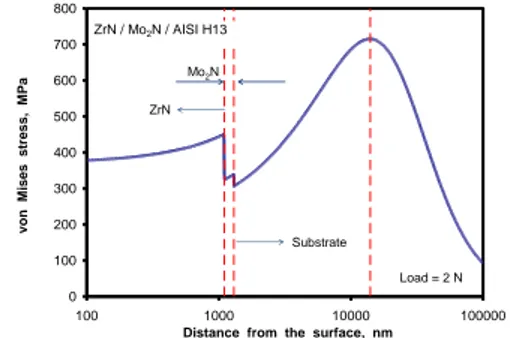
Figure 4 illustrates the predicted change in the von Mises stress with distance measured from the coating surface. In this case, it has been assumed that the coated system is subjected to spherical indentation with an applied load, F = 2 N. The determination of this plot is based on the results presented in Figure 3(b), which describes the change in the elastic modulus of the coated system as a function of indentation depth, as derived from the extended form of the Doerner and Nix model. However, the information concerning the value of the Poisson ratio for the different materials, which encompass the coated system, is also required. Thus, Table 1 summarizes the numerical data employed for conducting the required computations.
Table 1. Mechanical properties of the different materials, which constitute the coated system, employed in the computation of elastic stresses under spherical indentation loading.
ZrN Mo2N AISI H13 steel Al2O3 ball
0.186 (1) 0.3 (2) 0.33 0.231
E, GPa --- --- 210 416
, MPa 8067(*) 4833(*) 1650 (3) ---
(*) It has been assumed that the tensile strength of the coating is equal to 1/3 of its absolute hardness. (1) Perry, A.J, (1990) (2) Pappacena et al., (2012) (3) [www.matweb.com] 0 100 200 300 400 500 600 700 800 100 1000 10000 100000
Distance from the surface, nm
v on M is e s s tres s , M Pa ZrN / Mo2N / AISI H13 ZrN Mo2N Substrate Load = 2 N 0 100 200 300 400 500 600 700 800 100 1000 10000 100000
Distance from the surface, nm
v on M is e s s tres s , M Pa ZrN / Mo2N / AISI H13 ZrN Mo2N Substrate Load = 2 N
Fig. 4. Predicted change in the von Mises stress with the distance measured from the coating surface.
Thus, for a given depth, , measured from the surface of the coated system and taking into account the relationship between such a depth and the contact radius, a, the elastic modulus of the coating is interpolated from the predicted curve determined by means of the extended Doerner and Nix model. Subsequently, taking into consideration the elastic properties of the Al2O3 ball, the value of the reduced elastic modulus, Er(a, Eball,
ball), can be determined. In this way, it is possible to solve the non-linear equation which relates a, Er(a, Eball,
ball), F and the ball diameter, d, in order to compute the correct value of a. Concerning the computation of the
Poisson’s ratio for a given contact radius, which is required in order to determine both the principal stresses and the von Mises stress, a Heaviside step function has been employed.
The change in the von Mises stress with distance from the surface is carried out by employing the Hertzian equations, which correspond to the elastic contact between a spherical indenter and a multi-layer coating. Accordingly, the principal stresses at a given depth are determined as a function of a, the maximum pressure, Pmax, and the corresponding Poisson ratio value. In turn, Pmax depends on the load applied, F, and a.
However, in order to carry out this computation it is of utmost importance to take into consideration the strain compatibility at the ZrN/Mo2N and Mo2N/Substrate interfaces. For this purpose, as a first approximation,
it can be assumed that the principal strains at each interface, computed as a function of the von Mises stress and the elastic constants of the corresponding layer material, remain constant across each interface. Details of the equations employed and the computational procedure that has been followed have already been reported elsewhere (Staia et al., 2016).
Thus, when a normal load of 2 N is applied to this coated system, the contact radius is found to be of approximately 28.5 m and a maximum pressure of approximately 1180 MPa is attained at a depth of about 270 nm. However, the maximum von Mises stress is of approximately 715 MPa and it is located at a depth of 14000
nm, that is to say, well into the substrate. Since the yield strength of the H13 substrate is of approximately 1650 MPa, it will not undergo plastic deformation. Thus, the system is expected to behave elastically and therefore, the integrity of the bi-layer coating will be preserved.
3.2 Tribological performance
Fig. 5 shows the evolution of the friction coefficient for the coated system and for the steel substrate, respectively. This variation was represented only for 100 m of sliding distance although the test was run for 200 m, since after 80 m of the sliding distance, the value of the friction coefficient of the ZrN coated system reached the same value corresponding to the steel substrate.
It is observed that for the steel substrate, an increase in the friction coefficient value to 0.3 at the beginning of the test takes place, typical for the running-in period corresponding to the contact between the alumina ball and the sample. A continuous decrease in its value, due to the wash away process of the wear debris from the contact, takes place until the end of the test, reaching a steady state value of 0.14.
However, for the ZrN coated system it is observed that the friction coefficient increases at the beginning of the test to a value of 0.17 and, subsequently, drops to a constant value of 0.12, which is maintained until 30 m of sliding distance. After this value, the friction coefficient starts to increase as a consequence of the film mechanical damage produced due to the presence of the corrosive solution. It is worth mentioning that, due to the coating morphological characteristics and its small thickness, the penetration of the corrosive solution takes place, which contributes to undermining the coating itself due to a crevice corrosion phenomenon. The latter promotes the substrate dissolution that further weakens the coating under the normal load used during the wear test, due to the reduced load-bearing capacity of the substrate.
3.5% NaCl solution ZrN coated system Steel substrate 30 m
Fig. 5. Friction coefficient variation with the sliding distance for the coated and uncoated H13 steel substrate tested in 3.5 wt% NaCl solution
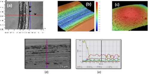
Fig. 6a and b illustrate the 3D profiles of the wear track after testing in the 3.5 wt% NaCl solution, whereas Fig. 6c shows the 3D image profile of the alumina counterpart. The SEM micrograph corresponding to the morphology of the worn ZrN coating is presented in Fig. 6d, indicating that the coating experienced a severe abrasive wear mechanism, due of the combined action of the ball and the hard “debris” products resulting from the coating damage. In some places, however, the existence of the coating it is still observed, a fact that is detected with greater clarity from the EDS line concentration profile performed on this wear track (see Fig. 6 d).
(c) (b)
(a)
(d) (e)
Fig. 6. (a) 3D profile of the wear track after testing in 3.5 wt% NaCl solution; (b) detailed 3D profile of the track; (c) 3D image profile of the alumina counterpart; (d) detailed SEM micrograph of the wear track; (d) EDS line concentration profile of the wear track from (d).
In order to put in evidence the synergistic effect of wear and corrosion, additional wear tests were carried out in air for shorter sliding distances, in order to check the integrity of the bi-layer coating architecture under the contact between the coating and the ball for the same loading conditions, but without the presence of the corrosive solution. These sliding distances were chosen in such a way as to allow the comparison with those distances that corresponded to the coating failure during the wear tests in the corrosive environment.
The results are presented in Fig. 7 and indicate an excellent behavior for the coating at 30 m sliding distance (test A), which corroborated that the integrity of the bi-layer coating was preserved, as predicted in section 3.1.1. As the sliding distance is increased, the debris produced as a consequence of the wear experienced by both counterparts will be present in the contact, contributing to a considerable increase in the friction coefficient value, from 0.2 (test A) to approximately 0.65 (test B). Nevertheless, under these conditions, the coated system still maintains its integrity, since the depth achieved through the coating thickness is not higher than 0.6 m, which is nearly half of its initial thickness. These latter experiments performed only in air, constituted a clear evidence of the deleterious effect of the presence of the corrosive solution, which promotes the substrate dissolution that further weakens the coating under the normal load used during the wear tests.
The SEM micrographs of the wear tracks for the 30 m and 63 m sliding distances, respectively, as well as the 3D profiles of both sample and counterpart for each condition are presented in Fig.8. As can be observed, a small amount of abrasive wear occurred for the sample and counterpart tested for 30 m (see Fig. 8(e)). However, after 63 m, considerable amount of wear debris were deposited on top of the alumina ball (Fig (f).
A
air
B
30m 63m
Fig.7. Friction coefficient variation with the sliding distance for the coated system tested in air. The wear test was stopped for curve: test A- at 30m; test B- at 63 m (e) (a) (c) (b) (d) (f)
Fig.8. (a) SEM micrograph of the wear track of the coated system after the dry test A for 30 m sliding distance; (b) SEM micrograph of the wear track of the coated system after the dry test B for 63 m sliding distance, (c) 3D profile of the wear track corresponding to (a); (d) 3D profile of the wear track corresponding to (b); (e) 3D profile corresponding to the alumina ball surface after 30 m sliding distance; (f) 3D profile corresponding to the alumina ball surface after 63 m sliding distance.
2D surface profiles are shown in Fig. 9 for all the tests, showing in each case a typical example of the cross section profile of the wear track, where both the experimental and computational description of the profile are represented. In order to determine the mean cross-sectional track area, six individual wear profiles were taken into account. The method of calculation is described elsewhere (Staia et al., 2016). The wear volume was
obtained by multiplying the cross-sectional wear track area by the length of the wear track.
The mean worn volume for the immersed coated sample was of 1.5 x10⁻² mm3 ± 0.04 x 10⁻² mm3
Correspondingly, the wear volume for test A was of 0.25 x 10⁻⁴ mm3 ± 0.01 x 10⁻² mm3 and 6 x 10⁻⁴ mm3 ± 0.05
x 10-2 mm3 for test B, both carried out without the presence of the corrosive solution. A specific wear rate, k,
per unit of sliding distance. Values of k of 0.4 x 10⁻¹⁵ m3/N m and 5 x 10-15 m3/N m, respectively, were obtained
indicating an increase of one order of magnitude when the sliding distance is doubled, which shows the effect of the presence of the hard debris in the contact. For comparison, the cross sectional area of the steel substrate tested in the same conditions as test B is also presented, indicating a value of nearly 418 m2 that corresponds to
0.85 x 10⁻¹⁴ m3/N m, that is to say 17 times greater than that corresponding to the coated system.
-5 -4.5 -4 -3.5 -3 -2.5 -2 -1.5 -1 -0.5 0 400 500 600 700 800 900 D is ta n c e fr o m th e s u rfa c e , m Width, m Area = 787 m2 (a) 3.5%NaCl sol. -0.7 -0.6 -0.5 -0.4 -0.3 -0.2 -0.1 0 100 200 300 400 500 600 D e p th , m Width, m Area = 5.94 m2 (b)
Test in air stopped at 30m sliding distance -0.7 -0.6 -0.5 -0.4 -0.3 -0.2 -0.1 0 400 500 600 700 800 900 1000 1100 D ep th , m Width, m Area = 24.6 m2
(c) Test in air stopped at63m sliding distance
-4 -3.5 -3 -2.5 -2 -1.5 -1 -0.5 0 0.5 0 200 400 600 800 1000 1200 1400 D e p th , m Width, m Area = 417.5 m2 Steel substrate (d) substrate
Fig.9. Typical cross section profiles of the wear track corresponding to: (a) wear track of the coated system after test in 3.5 wt% NaCl solution for 200 m; (b) wear track of the coated system after the test A carried out in air for 30 m; (c) wear track of the coated after the test B carried out in air for 60 m; (d) wear track of the substrate after the test carried in air for 60 m
As indicated above, in the present research, the wear tests were carried out by immersing the samples in a corrosive solution. However, Ferreira et al. (2006) have also reported a similar mechanism during wear testing of sputtered ZrOxNy coatings deposited on a M2 steel substrate, carried out under potentiostatic control in an
aggressive solution, such as artificial sweat. As in the present study (see Fig. 5), the value of the friction coefficient of the tested system, measured at the end of the tests, was controlled by the friction coefficient between alumina ball and M2 steel, due to coating damage. These results clearly indicate that, in order to predict the synergistic effect between the two phenomena, simple tests such as those employed in the present work could be conducted, avoiding the need of using more complex experimental setups.
4. Conclusions
In the present paper, the sliding wear performance of a ZrN coating deposited by means of CFUBMSIP has been evaluated in a 3.5 wt% NaCl solution. It has been determined that under the test conditions employed, the coating experienced a severe abrasive wear mechanism, due of the combined action between the alumina ball, the hard “debris” formed as a product of the mechanical damage of the film and to a phenomenon of crevice corrosion. The latter gave rise to the substrate dissolution that further weakened the coating under the normal load used during the wear test, due to the reduced load-bearing capacity of the substrate. An important aspect, which can adversely affect the coating wear performance in the corrosive medium, was that related to its low thickness, which allowed the rapid penetration of the corrosive medium through the defects up to the coating-substrate interface. Nevertheless, it has been shown that the coated system is able to increase the wear resistance of the substrate by more than one order of magnitude if the wear tests are carried out in air under the same conditions. The hardness and elastic modulus of the bi-layer ZrN/Mo2N coated system were determined by
means of nanoindentation techniques and modeled following an analytical approach previously proposed for multilayers coatings. The results of this analysis indicate that for the ZrN coating, HZrN = 24.2 GPa and EZrN =
444 GPa, whereas for the Mo2N coating, HMo2N = 18.2E and EMo2N = 354 GPa, respectively. The analysis of the
elastic stresses under the spherical contact between the ball and the coated system indicates that it is expected to behave elastically and, therefore, that the integrity of the bi-layer coating will be preserved.
Acknowledgements
Professor M. Staia acknowledges the financial support of the Scientific and Humanistic Development Council of the Universidad Central de Venezuela (CDCH-UCV). Professor Puchi-Cabrera acknowledges the financial support of the program Campus France and the infrastructure provided by the Laboratory LAMIH at the University of Valenciennes, France. The authors are also grateful to Teer Coatings (England) for providing the coated samples.
References
Auger, M.A., Araiza, J.J., Falcony, C., Sanchez, O. and Albella, J.M., 2007. Hardness and tribology measurements on ZrN coatings deposited by reactive sputtering technique, Vacuum 81, 1462–1465
Chou, W.-J., Yu, G.-P. and Huang, J.-H.,2003, Corrosion resistance of ZrN films on AISI 304 stainless steel substrate, Surface and Coatings Technology, 167., 59-67.
Doerner, M. F. and Nix, W. D., 1986, A method for interpreting the data from depth-sensing indentation instruments, Journal of Materials Research, 1, 601-609.
Ferreira, S.C., Ariza,E., Rocha, L.A., Gomes, J.R., Carvalho, P., Vaz, F., Fernandes, A.C., Rebouta, L., Cunha, L., Alves, E., Goudeau, Ph. and Rivière, J.P., 2006, Tribocorrosion behaviour of ZrOxNy thin films for decorative applications, Surface & Coatings Technology 200, 6634- 6639
Fragiel, A., Staia, M.H., Muñoz-Saldaña, J., Puchi-Cabrera, E.S., Cortes-Escobedo, C. and Cota, L.,2008, Influence of the N2 partial pressure on the mechanical properties and tribological behavior of zirconium nitride deposited by reactive magnetron sputtering, Surface & Coatings Technology 202 , 3653 – 3660
Huang, J.-H., Yang, H.-C., Guo, X.-J. and Yu, G.-P., 2005, Effect of film thickness on the structure and properties of nanocrystalline ZrN thin films produced by ion plating, Surface & Coatings Technology 195, 204– 213
Jauberteau, I., Bessaudou, A., Mayet, R., Cornette, J., Jauberteau J. L., Carles, P. and Merle-Méjean,T., 2015, Molybdenum Nitride Films: Crystal Structures, Synthesis, Mechanical, Electrical and Some Other Properties, Coatings 2015, 5, 656-687; doi:10.3390/coatings5040656
Jianxin, D., Jianhua, L., Jinlong, J .and Wenlong, S., 2008, Wear mechanisms of PVD ZrN coated tools in machining International Journal of Refractory Metals & Hard Materials 26, 164–172
Lina, C.-C., Leeb, J.-W., Changa, K.-L., Hsieha, W.-J., Wanga, C.-Y., Changa, Y.-S., Shiha, H. C., 2006, Surface & Coatings Technology 200, 2679 – 2685.
Lopez G. and Staia M.H., 2005, High-temperature tribological characterization of zirconium nitride coatings, Surface & Coatings Technology 200 (2005) 2092–2099
Ningshen, S., Gupta, R. K., Kamal S., Chawla, V., Chandra, R., Mudal, U. K., 2013, Corrosion Study of ZrN deposited on 304L Stainless Steel, Surface Engineering 29, 4, p.264-270.
Pappacena, K.E., Singh, D., Ajayi, O.O., Routbort, J.L., Erilymaz, O.L., Demas, N.G. and Chen, G, Residual stresses, interfacial adhesion and tribological properties of MoN/Cu composite coatings,Wear 278– 279 (2012) 62– 70
Perry, A.J, 1990, Thin Solid Films 193/194, 463-471
D. Pilloud, A.S. Dehlinger, J.F. Pierson, A. Roman and L. Pichon, 2003, Reactively sputtered zirconium nitride coatings: structural, mechanical,optical and electrical characteristics, Surface and Coatings Technology 174 –175, 338–344
Puchi-Cabrera, E. S., 2002, A new model for the computation of the composite hardness of coated systems, Surface and Coatings Technology, 160, 177-186.
Puchi-Cabrera, E. S., 2004, Computation of composite hardness of coated systems, Surface. Engineering, Vol. 20, No. 5, 332-344.
Puchi-Cabrera, E. S., Staia, M. H. and Iost, A., 2015, Modeling the composite hardness of multilayer coated systems, Thin Solid Films 578, 53–62.
Puchi-Cabrera, E. S., Staia, M. H. and Iost, A., 2015, A description of the composite elastic modulus of multilayer coated systems, Thin Solid Films 583, 177–193.
Singh, A., Kumar, N., Kuppusami, P., Prasanthi, T.N., Chandramohan, P., Dash, S., Srinivasan, M.P., Mohandas, E., and Tyagi, A.K., 2012, Tribological properties of sputter deposited ZrN coatings on titanium modified austenitic stainless steel, Wear 280– 281, 22– 27 M.H. Staia, E.S. Puchi-Cabrera, A. Iost, E. Carrasquero, Y.Y. Santana Mendez, J.G. La Barbera Sosa, D. Chicot, A. Van Gorp, 2013,
Sliding wear of a-C:H coatings against alumina in corrosive media, Diamond and Related Materials, Volume 38, Pages 139–14 Staia, M.H., Dubar, L., Dubar, M., Puchi Cabrera, E.S., Iost, A., De Baets, P., and Dubois, A., 2016 Mechanical characterization of a
prototype a-C:Cr,Si and its tribological behavior at high temperature, Tribology International, http: //dx.doi.org/10.1016/ j.triboint.2016.01.048
Sun, C.-.C, Lee, S.-C. , Hwang, W.-C., Hwang, J.-S., Tang, I-T., Fu, Y.-S., 2006, Surface Free Energy of Alloy Nitride Coatings Deposited Using Closed Field Unbalanced Magnetron Sputter Ion Plating, Materials Transactions, The Japan Institute of Metals, Vol. 47, No. 10, 2533 to 2539.
Thornton, J.A.,1986, The microstructure of sputter-deposited coatings, Vac. Sci. Technol. A 4 (6), 3059-3063
Tӧrok E, Perry A.J., Cholet L., Sproul W.D.,1987, Young´s modulus of TiN, TiC, ZrN and HfN, Thin Solid Films 153, 37-43
Valerini, D., Signore, M.A., Tapfer, L., Piscopiello,E., Galietti ,U. and Rizzo , A., 2013, Adhesion and wear of ZrN films sputtered on tungsten carbide substrates, Thin Solid Films 538, 42–47