Science Arts & Métiers (SAM)
is an open access repository that collects the work of Arts et Métiers Institute of Technology researchers and makes it freely available over the web where possible.
This is an author-deposited version published in: https://sam.ensam.eu
Handle ID: .http://hdl.handle.net/10985/11617
To cite this version :
Karim BENOUARETH, Pascal TRISTANT, Cédric JAOUL, Christophe LE NINIVEN, Corinne NOUVEAU, Christelle DUBLANCHE-TEXIER, Abderrahman BOUABELLOU - Study of the interaction between a Zirconium thin film and an EN C100 steel substrate: temperature effect -Vacuum - Vol. 125, p.234-239 - 2016
Elsevier Editorial System(tm) for Vacuum Manuscript Draft
Manuscript Number: VAC-D-15-00218R1
Title: Study of the interaction between a Zirconium thin film and an EN C100 steel substrate: temperature effect.
Article Type: Full Length Article
Keywords: Zirconium Carbide; Sputtering; heat treatment; Diffusion; Hardness. Corresponding Author: Mr. karim benouareth,
Corresponding Author's Institution: First Author: karim benouareth
Order of Authors: karim benouareth; Tristant Pascal, prof.; Jaoul Cedric; Le Niniven Christophe; Nouveau Corinne ; Dublanche-Tixier Christelle; Bouabellou Abderrahman
Abstract: Zirconium thin films were grown on high carbon steel substrates EN C100 (1 %wt. of carbon) by RF magnetron sputtering. In order to study the reactivity of the film/substrate system as a function of the temperature, one hour vacuum annealing was carried out for different temperatures between 600°C and 1100°C. The films were then analyzed by X-ray diffraction, scanning electron microscopy, glow discharge optical emission spectroscopy (GDOES) and nanoindentation.
The obtained results showed a progressive transformation of zirconium film to zirconium carbide. Carbon atoms diffusion from substrate toward the film induced this transformation. The sample annealed at 900°C exhibited the best mechanicals properties (H =17 GPa and E = 220 GPa). Samples treated at higher temperature were affected by oxidation and high microporosity. Even if the conversion is uncomplete, annealing significantly promotes adhesion of the film on the substrate. Suggested Reviewers: Rizzo Antonella
Department of Advanced Physical Technologies and New Materials, Italian National Agency for New Technologies,Energy and the Environment (ENEA), CR Brindisi, S.S. 7 Appia, 72100 Brindisi, Italy antonella.rizzo@brindisi.enea.it
she worked a lot on zirconium layers chicot didier
Université de Lille 1 didier.chicot@univ-lille1.fr
Good Evening
We have revised the manuscript based on the comments of the editorial board Firstly, we would like to inform you that the study takes as a model the reactivity between a Zirconium coating and a carbon-rich substrate.
The nuance of substrate (EN C100) was not selected for its applications but because it is rich in carbon.
For the first point,
Hard coatings fabricated by habitual physical vapor deposition have a poor film quality due to porous microstructure and weak adhesion[2]. Also, adhesion problems related to the different thermal expansion coefficients of the coating and substrate material were also observed [3]. Many researches were done to make hard coatings with high adhesion by using controlled arc plasma deposition [4], plasma focus device [5] or through deposition by combined magnetron deposition and ion implantation [6] and by thermo-reactive diffusion deposition[7].
Relying on the process of the thermally activated atomic interdiffusion between the chemical elements at the coating/substrate interface, we try to manufacture, in the current work, a zirconium carbide hard coating with good adhesion and mechanical properties by conversion from a zirconium film deposited on high carbon steel. This transformation is likely to occur based on the role of carbon diffusing from the substrate into the film through a post-deposition annealing of the coating/substrate system at different temperatures (600°C – 1100°C). The zirconium, which is in the IV group of transition elements, is chosen because its alloys have excellent properties such as a low thermal expansion, and they are strongly heat resistant [8]. Zirconium is widely employed in industrial devices being used in aerospace, optoelectronics, and chemistry [9]. Its high melting point and low thermal neutrons capture cross section allows it to be used in nuclear reactor installations [8, 10]. Zirconium is applied as an alloy or ceramic in medical implants because it is biocompatible in the human body [11]. The carbide form, ZrC, is widely employed in industry because of its good properties (thermal, chemical, optoelectronical), and excellent corrosion and wear resistances [10, 12-14].
For the second point;
The hardness of the substrate for the unannealed specimen is between 3 and 4 GPa. It remains in the same range after annealing between 600 and 800°C, in the contrary to the annealing at higher temperatures, 900 to 1100°C, where the hardness rises to values between 5 and 6 GPa, Fig.8. On the other hand, there is no observed significant decrease in the level of carbon signal at substrate in GDOES analyses after heat treatment in comparison to the pristine substrate, Fig.3. This indicates that there is no considerable carbon depletion gradient in the uppermost region of the substrates. These observations prove that the diffusing carbon atoms in the film does not result in the decreases in mechanical properties of the substrate. The thickness of the film is lesser 10-3 times than the substrate thickness, which confirms our conclusions.
The pristine substrate has a microstructure formed of ferrite and globular cementite, which indicates that the steel has undergone a spheroidizing treatment. This treatment is used to improve the ability to cold deformation of steel. It has a purpose to enhance the ability to use steels by making possible the application of high cutting speeds and insuring a very well state of surface.
By annealing an hypereutectoid steel (content of carbon is upper to 0,77 wt.%), when the temperature rises just above the eutectoid (727°C), the ferrite transforms to austenite by the diffusion of carbon from cementite grains. If the temperature continues to rise, the austenite may dissolve more carbon until a temperature slightly higher than 800°C, where all the ferrite and cementite are transformed in austenite. By cooling, the inverse phenomenon happens; the austenite transforms to pearlite and cementite. The pearlite is the heterogeneous mixture (aggregate) of ferrite and cementite. Consequently, the microstructure of steel changes from globular to lamellar cementite, this later microstructure is harder which results in the noticed rise of the substrate hardness values after the thermal cycle.
The microstructure and properties of the steel depends on the cooling rate. Quenching to be considered, if we wanted to optimize.
Hope that we have answered your comments. Best Regards
References
[1] S. T. Oyama, The Chemistry of Transition Metal Carbides and Nitrides, Blackie A & P, First edition, London, UK, 1996, 535 p.
[3] J. Brockner, T. Mantyla Surface and Coatings Technology, 59 (1993) 166—170 [4] J.-D. Gu, P.-L. Chen, Surface & Coatings Technology 200 (2006) 3341 – 3346
[5] I.A. Khan, S. Jabbar, T. Hussain, M. Hassan, R. Ahmad, M. Zakaullah, R.S. Rawat, Nucl. Instrum. Meth. Phys. Res. B 268 (2010) 2228.
[6] E. Grigore, C. Ruset, K. Short, D. Hoeft, H. Dong, X.Y. Li, T. Bell, Surf. Coat. Technol. 200 (2005) 744 [7] A. OrjuelaG., R. Rincón, J. J. Olaya, Surface & Coatings Technology 259 (2014) 667–675
[8] Y.C. Kang, M.M. Milovancev, D.A. Clauss, M.A. Lange, R.D. Ramsier, Journal of Nuclear Materials 281 (2000) 57-64. [9] L. Pichon, T. Girardeau, F. Lignou, A. Straboni, Thin Solid Films 342 (1999) 93-99.
[10] G. Murtaza, S.S. Hussain, N.U. Rehman, S. Naseer, M. Shafiq, M. Zakaullah, Surface & Coatings Technology, 205 (2011), 3012–3019.
[11] N. Ozkucur, C. Wetzel, F. Hollstein, E. Richter, R. H. W. Funk, T. K. Monsees, Journal of Biomedical Materials Research Part A.
[12] D. Craciun, D. Craciun, G. Socol, N. Stefan, I.N. Mihailescu, G. Bourne, V. Craciun, Surface & Coatings Technology, 203 (2009), pp.1055–1058.
[13] C.-S. Chen, C.-P. Liu, C.-Y.A. Tsao, Thin Solid Films, 479 (2005), p. 130–136. [14] K. Nakamura, M. Yashima, Materials Science and Engineering B 148 (2008) 69–72.
Zr thin films of 3.5 µm were deposited by RF magnetron sputtering on EN C100 steel. Specimens were vacuum annealed for one hour from 600 to 1100 °C.
The structural and mechanical properties of the coatings were then studied.
The annealing has induced a progressive transformation of Zirconium film to Zirconium carbide. This transformation is induced by carbon atoms diffusion from substrate into film.
Study of the interaction between a Zirconium thin film and an
EN C100 steel substrate: temperature effect.
Karim Benouaretha,b,*, Pascal Tristantb, Cedric Jaoulb, Christophe Le Ninivenb, Corinne Nouveauc, Christelle Dublanche-Tixierb, Abderrahman Bouabelloua
aUnité de Recherche de Physique des Matériaux et Applications, Université de Constantine 1, Route de Ain El-bey,
25000, Constantine, Algérie.
bScience des Procédés Céramiques et Traitements de Surface, SPCTS, UMR CNRS 7315, Université de Limoges, ENSIL, 16 rue Atlantis,
87068 Limoges, France.
cLaboratoire Bourguignon des Matériaux et Procédés, LaBoMAP, Centre Arts et Métiers de Cluny, Rue porte deParis,
71250 Cluny, France. * Corresponding author. Tel.: +213 55 4124365; Fax: +213 31 818664;
E-mail address: kariarth@yahoo.fr (K. Benouareth).
Abstract
Zirconium thin films were grown on high carbon steel substrates EN C100 (1 %wt. of carbon) by RF magnetron sputtering. In order to study the reactivity of the film/substrate system as a function of the temperature, one hour vacuum annealing was carried out for different temperatures between 600°C and 1100°C. The films were then analyzed by X-ray diffraction, scanning electron microscopy, glow discharge optical emission spectroscopy (GDOES) and nanoindentation.
The obtained results showed a progressive transformation of zirconium film to zirconium carbide. Carbon atoms diffusion from substrate toward the film induced this transformation. The sample annealed at 900°C exhibited the best mechanicals properties (H =17 GPa and E = 220 GPa). Samples treated at higher temperature were affected by oxidation and high microporosity. Even if the conversion is uncomplete, annealing significantly promotes adhesion of the film on the substrate.
Keywords: Zirconium Carbide; Sputtering; heat treatment; Diffusion; Hardness.
1. Introduction
Nowadays, the materials surface properties have more and more important roles in many industrial applications. For example, for metallic parts of tools (fabricated with steel commonly) undergoing mechanical solicitations or those submitted to aggressive environments, it is possible to increase their resistance to corrosion or wear by modifying the material's surface. One of most applicable techniques is to coat the surface with a film. The metallic matrix provides the structural properties *Manuscript
whereas the film brings the surface properties. The thin film (thickness less than 10 µm) can be enough to increase the life expectancy of these elements. However, a good adhesion of the coating to the substrate is essential for a successful application [1]. Hard coatings fabricated by habitual physical vapor deposition have a poor film quality due to porous microstructure and weak adhesion [2]. Also, adhesion problems related to the different thermal expansion coefficients of the coating and substrate material were also observed [3]. Many researches were done to make hard coatings with high adhesion by using controlled arc plasma deposition [4], plasma focus device [5] or through deposition by combined magnetron deposition and ion implantation [6]and by thermo-reactive diffusion deposition[7].
Relying on the process of the thermally activated atomic interdiffusion between the chemical elements at the coating/substrate interface, we try to manufacture, in the current work, a zirconium carbide hard coating with good adhesion and mechanical properties by conversion from a zirconium film deposited on high carbon steel. This transformation is likely to occur based on the role of carbon diffusing from the substrate into the film through a post-deposition annealing of the coating/substrate system at different temperatures (600°C – 1100°C). The zirconium, which is in the IV group of transition elements, is chosen because its alloys have excellent properties such as a low thermal expansion, and they are strongly heat resistant [8]. Zirconium is widely employed in industrial devices being used in aerospace, optoelectronics, and chemistry [9]. Its high melting point and low thermal neutrons capture cross section allows it to be used in nuclear reactor installations [8, 10]. Zirconium is applied as an alloy or ceramic in medical implants because it is biocompatible in the human body [11]. The carbide form, ZrC, is widely employed in industry because of its good properties (thermal, chemical, optoelectronical), and excellent corrosion and wear resistances [10, 12-14].
2. Experimental
2.1. Films Preparation
Pure Zr thin films of 3.5 µm thickness were deposited by RF magnetron sputtering. The distance between the target of pure Zr and the substrate holder was fixed at 100 mm. The base vacuum of the chamber was kept at 10-5 Pa. During deposition, the working pressure was fixed at 0.3 Pa with a carrier gas of Argon (99.99 % purity). The deposition duration is 250 minutes, the RF power is 400 W with a target polarization of -900 V and a substrate temperature of 200 °C.
High carbon steel (EN C100 or AISI 1095), 1 %wt. of carbon, in the spheoridized state was chosen as the substrate. The disk shape substrates, of 30 mm in diameter and 4 mm in thickness, are firstly
polished using a BUEHLER EcoMet 250 polishing machine. To obtain an average roughness Ra of about 20 nm, a precision polishing was carried by 2400 SiC papers. Substrates were then ultrasonically cleaned for 10 min in ethanol, followed by 10 min in acetone. Prior to deposition, the surface of the substrate was cleaned 10 min by high purity (99.99 %) Argon plasma at a pressure (1 Pa). The ion bombardment induced by the polarization of the samples (-954 V) allowed to remove impurities and native oxides at the surface.
2.2. Post-deposition treatment
Zr/C100 specimens were vacuum annealed for one hour at temperatures ranging from 600 to 1100 °C, in a tubular furnace. The pressure of 10-2 Pa was ensured by a diffusion pump. Heating rate was set at 10 °C/min, while that of cooling was 20°C/min.
2.3. Characterization and analysis
The structure and phase composition of the coatings were assessed by X-ray diffraction (XRD) using a conventional Siemens D5000 diffractometer with Cu Kα radiation operating in the Bragg– Brentano configuration. Measurements were performed at room temperature after thermal treatments. Surface and cross section morphology were examined with a Scanning Electron Microscope (SEM). To investigate the phenomena occurring at the film/substrate interface, glow discharge optical emission spectroscopy (GDOES) experiments were performed using a Horiba Jobin Yvon RF GD Profiler equipped with a 4 mm diameter anode and operating at a typical radio frequency discharge pressure of 650 Pa and a power of 20 W.
Hardness and elastic modulus were determined by load–displacement data obtained using a XP nanoindenter model MTS Systems equipped with Berkovich tip, by means of 40 indents per sample for the surface nanohardness. The depth nanohardness measurements were performed on specimen's cross-sections (perpendicularly to the films surface) going from the film surface to the substrate where each indent is spaced by 0.7 μm from the other. The nanohardness value for each depth position is obtained by averaging 4 indents.
3. Results and discussion
3.1. Morphology
The Zr/C100 pristine sample surface shows a reflecting metallic gray appearance while samples treated at high temperatures have a dull blackish brown aspect. The surface of the deposited film has a smooth uniform morphology, Fig. 1-a, with a microstructure characterized by fine grains in nano-domes form, with diameters of a few tens of nanometers, but polishing scratches are still visible. This morphology is characteristic of a growth developed by agglomeration of atoms. The cross section observation of the same sample, Fig. 2-a, shows the existence of a columnar structure which is typical to the zone II according to Thornton’s model. This zone is described by a homogeneous structure along the film thickness composed of straight columns, elongated perpendicularly to the substrate surface, from the bottom to the top of the film without intercolumnar voids [15]. In spite of the very low deposition temperature (200 ºC) compared to the melting point for Zr (1855 ºC), the observed morphology is denser than Thornton prediction. This densification is observed for films deposited by PVD under high energy conditions characterized by an intense ion bombardment, limited mobility conditions and high deposition rates [16, 17].
The deposited film suffers from a poor adherence due to the low deposition temperature. This is highlighted in Fig. 2-a where the film is detached from the substrate after the cross section preparation.
After annealing at moderate temperatures, 600-800 °C, the film surface appears smoother with denser microstructure (not shown in this paper). The heat treatment leads to the growth and coalescence of grains, and the annihilation or the displacement to the grain boundaries of the structural defects (voids, gaps). The film adheres perfectly to the substrate due to diffusion that increases the film hooking to substrate. All these observations reflect a better crystallinity of the film after annealing.
At higher temperatures, Fig. 1-c, the surface morphology becomes rough and porous with nodular bigger grains. The film surface is more homogeneous by the disappearance of polishing scratches observed for lower annealing temperature. Although the grain size increases after annealing, the grains are formed of clusters composed of small crystallites, specifically for annealing at 1100 °C (greatest magnification of the Fig. 1-b and 1-c).
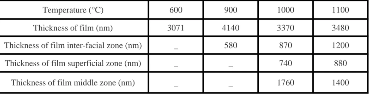
At 900 °C, from the SEM cross-sectional images, a different (darker) contrast zone of 580 nm thick appears in the film close to the interface (film/substrate), especially using backscattered electrons mode (Zone 1, Fig. 2-b). While the other part of the film still with the same aspect as those of lesser annealing temperature (Zone 2, Fig. 2-b). Another area with the same (darker) contrast appears near
the film surface at 1000 °C and at the same time, the surface roughness increases. The film surface appears very rough and very porous (Zone 3, Fig 2-c). These two zones increase in thickness when the annealing temperature increases (Table 1). Between the tow peripherals dark zones, the film middle zone appears bright with a decreasing width by rising annealing temperature. These observations will be later discussed.
After annealing, the samples do not show any cracks on the surface or in the thickness for the different temperatures studied. These cracks, usually observed after annealing and cooling of the whole coating/substrate, are related to the mismatch of the heat expansion coefficients between the two components. In our case, the creation of an inter-facial connection zone between the coating and the substrate absorbs the mismatch. This is also connected to the film low grains size and the high concentration of grain boundaries having the effect of relaxing the stress, which prevents cracks propagation.
3.2. Qualitative analysis by glow discharge optical emission spectroscopy (GDOES)
The GDOES of unannealed Zr/C100 sample analysis, Fig. 3-a, shows that the raw film does not contain carbon. It is clear that signals of both oxygen and carbon are slightly higher at film surface, this comes from the inevitable contamination by impurities before performing analysis.
After annealing at 600 °C, on the carbon signal, a small hump develops at the interface coating/substrate (in the film side) indicating the beginning of its diffusion. By rising the annealing temperature, the film carbon signal gains in intensity and depth in this region (zone 1), Fig.3-b, but it also increases in the middle region (zone 2), and reaches progressively, at higher temperatures, the surface region (zone 3) , Fig.3-c , confirming that the diffusion of carbon atoms from substrate to the Zr film is thermally activated. At the same time, the intensity of zirconium signal decrease by increasing annealing temperature, which suggests its reaction with the carbon to form the carbide. The interface zone is favoured by diffusion because it is close to carbon atoms source (i.e. substrate), for this reason we observe that this region (zone 1) receive always the greatest amount of carbon atoms. Another factor promoting the carbon diffusion is the film microstructure composed of columnar grains of nanometric size with grain boundaries elongated perpendicularly to film surface.
Each time we elevate the annealing temperature, the film uppermost surface is subject of light contamination by oxygen and carbon, which is testified by the increase of their signals in this region, (Zone 3), Fig. 3-b. However, it is clear that the contamination with carbon is more important in the uppermost surface at 1000 °C and especially 1100 °C, while the oxygen contamination progress in the film thickness and reach gradually the middle of the film (Zone 2), Fig 3-c. It seems
that it is due to the higher reactivity of oxygen with zirconium than carbon. After annealing, the GDOES elements signals flatten confirming the interdiffusion and the reaction of the film with the substrate, thus logically the adhesion rises.
The superimposition of these results with those of SEM observations, show that the first darker contrast region (zone 1, Fig. 3-b and , Fig. 3-c) is due to the diffusion of carbon, while the second darker contrast region (zone 3, Fig.3-c) is the imprint of the contamination by oxygen and carbon. The bright contrast region in the middle (zone 2, Fig. 3-c) contains less interstitial elements (i.e. carbon and oxygen) than the two first regions. The carbon in this later zone may not be due to the carbon diffusion, as the carbon atoms cannot cross the middle zone and diffuses directly to the surface. We will confirm this conclusion in the next section. The source of carbon contamination may be due to the backstreaming of the oil from the diffusion pump that could decompose in the annealing furnace at high temperature.
3.3. XRD analysis
X-ray diffraction patterns of Zr/C100 samples as deposited and annealed at temperatures ranging from 600 to 1100 °C are presented in Fig. 4. For the pristine sample, only the hexagonal zirconium alpha phase is detected, as an additional peak attributed to the substrate (alpha iron). The diffraction peaks are wide, which is associated with a small crystallite size (grain fineness), and large microstrain due to the presence of structural defects. An anisotropic shape is observed that can be caused by stress, this also indicates that the crystallites have an anisotropy shape [18].
The zirconium X-rays diffraction pattern becomes narrower and more intense after annealing at 600 °C. This is explained by the increase in the crystallite size and an improvement in the film crystallinity and density: partial removal of structural defects, and a stress relaxation in the film. From 700 °C, the zirconium peaks intensities begin to decrease and disappear completely at 1100 °C.
At 600 °C, in addition to the peak of zirconium and substrate, a new small peak appears, identified as the plane (111) of the FCC substoichiometric ZrC0.6 zirconium carbide phase, which confirms the beginning of carbon atoms diffusing from substrate to the film. This diffusion leads to the formation of grains of the carbide phase at the interface of the film. Two phases, zirconium carbide and zirconium coexist between 600 and 1000 °C. Though the zirconium carbide phase is the minor phase at low temperature annealing, by raising temperature, it becomes the predominant phase at 900 °C and remains the only phase at 1100 °C. This reflects a gradual transformation of the zirconium film to zirconium carbide. Every time we raise the temperature, we stimulate a greater amount of carbon atoms to migrate to the film, which leads to the observed increase of the
zirconium carbide peaks intensities. This is in good agreement with other works, where coatings of transition metal carbides have been successfully manufactured from transition metals thin films deposited on high carbon steel [19-21].
Typically, it is known that transition metals are highly reactive; they are not stable in chemical environments containing light elements. Since the zirconium carbide is an interstitial compound, the inclusion of carbon in zirconium lattice is produced by its incorporation into interstitial sites of the lattice. It has a much smaller radius compared to the zirconium atom and this is manifested by increased stability and moderate chemical reactivity of the system [22].
By rising the annealing temperature, the carbide diffraction peak shift to lower diffraction angles (towards the stoichiometric ZrC theoretical position); see for example (111) peak presented in Fig. 5. This suggests a cell expansion due to the incorporation of more carbon atoms in the zirconium lattice. From 900 °C, the carbide (111) peak position is between the theoretical position of ZrC0.6 (2θ=33.186°, according to JCPDS card No. 65-9886) and that of the stoichiometric ZrC (2θ=33.040°, according to JCPDS card No. 35-0784). Even if the (111) peak of the two phases are very close, their overlap show that a mixture of ZrC0.6 and ZrC phases coexist at high annealing temperature. The same conclusion has been reported by E. Grigore et al. [23]. The total volume of substoichiometric carbide grains in the film is more important than that of stoichiometric carbide, since the position of the (111) diffraction peak is always closer to the substoichiometric phase. From 600 to 1100 °C, Fig. 4, two peaks from the substrate (the alpha phase of iron) are present with a nearly constant intensity, which means that all the film is analysed.
At 1100 °C, low intensity diffraction peaks are detected at low angles and are attributed to the zirconium oxide ZrO2 monoclinic phase according to JCPDS card No. 04-4339, with the arrival of the main peak at the angle 28.2° as the (-111) plane in agreement with the work of Kato et al. [24]. The monoclinic phase is the stable zirconium oxide phase at room temperature up to 1170°C. Zirconium substoichiometric carbide is certainly subject to oxidation, which can be deduced from the heats of formation of ZrC (-202.0 kJ mol-1) and ZrO2 (-1101.3 kJ mol-1). The reacting oxygen probably comes from the inevitable outgassing of the walls of the vacuum system for high annealing temperatures which provides steam oxygen in the vacuum chamber atmosphere. In the literature, the presence of zirconium oxide is still observed in zirconium films deposited by PVD whatever the vacuum used during the operation of the depositing [12, 22, 26-28], and after vacuum annealing of bulk zirconium [29]. S.-W. Yeh et al. showed that the deposition under a vacuum of 6.7×10⁻² Pa, leads to the formation of zirconium oxide for a 350°C substrate temperature. At 450 °C, the cubic zirconium oxide phase is observed [25]. Even, small amounts of oxides are detected in the zirconium films after the subsequent annealing at 700°C for 45 min under a pressure of 5×10⁻²
Pa, with the injection of a hydrogen gas flow [9]. This could be attributed to the higher affinity of zirconium for oxygen than that for carbon.
For the higher annealing temperature, the zirconium film was not completely converted to stoichiometric zirconium carbide, as the carbon signal is not uniform in the film (GDOES results). This can be explained by the deficiency of the diffusing flux of the carbon from the substrate to occupy all the octahedral sites in the zirconium lattice, and by the oxygen contamination at higher temperatures which could hinder the diffusion of carbon. An annealing treatment at 900°C for a longer time would be necessary to completely convert the zirconium film into zirconium carbide and to avoid the oxide phase formation.
It is difficult to detect oxycarbide phase formation by XRD because both ZrCO and ZrC have the same FCC structures with negligible difference in their lattice parameters [30]. In our case, the formation of ZrCO phase is favoured by the vacant octahedrals sites in ZrC0.6 cell, which accommodate the oxygen atoms. Researchers have noted that oxygen could dissolve in ZrC, leading to oxycarbide formation in which carbon and oxygen incorporate randomly into the interstitial sites in the zirconium lattice [30-34]. A recent study shown that oxygen atoms are incorporated either in the ZrC lattice or in an amorphous phase at the grains boundaries [32].
By superposition of XRD results with those of SEM and GDOES, we can conclude that the different contrast zone in the interface is the imprint of carbon diffusion, since this zone appears for the region where the intensity of GDOES carbon signal becomes high. This is simultaneous to the predominance of the carbide phase in the X-ray diffraction spectra at 900 °C together with the stoichiometric carbide formation. Despite of the carbide formation between 600 and 800 °C, it was noted that there is no observation of different contrast zone, on the contrary to higher annealing temperature. Thus, the stoiciometric carbide, not the substoichiometric one, causes the darker contrast zone in the interface.
The other different contrast region (zone 3) on the surface is caused by oxygen diffusion from the surface. Because the apparition of this zone, from 1000°C, is simultaneous to the apparition of ZrO2 peaks at high annealing temperatures, Fig. 4, together with the high contamination by oxygen observed by GDOES in the zone 3, Fig.3-c , where the oxygen signal is more important than the carbon one. Since an area with light elements appears darker than the heavier ones, the middle film (bright zone) contains less light interstitial elements than external zones, in good agreement with GDOES analysis. As unreacted zirconium was not obviously present in the XRD patterns at high temperature annealing, the film middle zone is composed of ZrC0.6 and ZrCxOy.
3.3.1. Cell parameters
The lattice constants were calculated according to the well-known relations: 1/ d2hkl= 4(h2+hk+k2)/3a2+l2/c2 for the zirconium carbide phase (hexagonal structure), and the
relation a = dhkl (h2+k2+l2)½ for the zirconium phase (cubic structure), where h, k and l are Miller indices.
We have chosen the (100) and (002) peaks for the calculation of the constants, a and c, of the hexagonal phase, respectively. The (111) peak is selected for the calculation of the cell parameter of the cubic phase.
The dhkl interplanar distance is defined by Bragg’s law.
Both lattice parameters (a and c) of the zirconium hexagonal phase evaluated for the unannealed sample are higher than the bulk parameters, a = (3.254±0.008)Å, c = (5.176±0.012)Å, this corresponds to a larger volume lattice, this may be related to the incorporation of foreign atoms in the lattice, or to microstructural defects. It is known that the substrate temperature is the major factor that affects the final structure of a PVD coating during deposition operation. If it is low, there is not enough energy for the mobility of zirconium adatoms to rearrange on the surface [16, 17]. Nevertheless, the ratio c/a is lower than the one of bulk zirconium. This could be caused by compressive stress in the perpendicular plane to the film surface (plane c) induced by plasma intense bombardment used during deposition.
Researchers have found, by varying substrate temperature from 25 to 600 ºC for zirconium films prepared by pulsed magnetron sputtering, that lattice parameters were always higher than the bulk lattice parameters which is attributed to the presence of compressive stress in the films [35]. The same interpretation has been reported in other works [36, 37].
After annealing, the parameters a and c are reduced due to, stress relaxation, defects elimination and atoms best rearrangement, however they remain higher. For example, at 800°C they become: a = (3.261±0.007)Å and c = (5.184±0.011)Å, this result is due to the inclusion of carbon atoms, coming from substrate (and eventually oxygen contamination) in zirconium lattice. This insertion increases gradually as the annealing temperature rises.
When the temperature reaches 863 °C, the structure of zirconium changes from hexagonal Zr-α to to body-centered cubic Zr-β. The latter structure is not suitable to accommodate the important flow of carbon atoms from the substrate in its small octahedral sites [38]. Therefore, to form carbide, the metal lattice must change to a compact structure (FCC or HCP), which provides larger octahedral sites for hosting carbon atoms; the compact structure being in turn stabilized by the interstitials atoms [38, 39].
The calculated lattice parameter for the FCC zirconium carbide phase for the sample annealed at 800°C is 4.666±0.009 Å, which corresponds to the theoretical value of the carbide ZrC0.6 (JCPDS file No. 65-9886). The formation of the substoichiometric phase means that the diffusing carbon atoms of the substrate do not fill the zirconium cells already occupied by a few atoms of zirconium, but diffuses to other grains and occupy zirconium lattices that have all, or almost, of their octahedral sites empty.
After annealing, the lattice parameter rises continuously with a value of 4.679±0.003 Å at 1100 °C, showing the expansion of zirconium lattice due to the insertion of more carbon atoms. The latter value is lower than the bulk zirconium carbide and higher than that of substoichiometric (ZrC0.6), which indicates the presence of the two phases at higher temperatures, as discussed previously. A lower lattice parameter was observed for ZrC film deposited by sol gel [31]. The most credible interpretation here is that there are vacant octahedral sites in the zirconium cell. The same interpretation has been reported for ZrN [40] and TiN films [28], which both possess the same FCC structure as ZrC. The ZrC lattice parameter depends considerably on composition, it increases with increasing C/Zr ratio and reaches a maximum for C/Zr~0.83, then it decreases [34]. Moreover, from JCPDS files, the stoichiometric zirconium carbide, which corresponds to the filling of all octahedral sites, has a larger lattice parameter than that of the substoichiometric carbide in ZrC0.6. At the same time, inserted oxygen is known to reduces the lattice parameter in ZrC by substituting carbon atoms, as the atomic radius of oxygen (rO = 0.66 Å) is inferior to that of carbon (rC = 0.76 Å). In addition, it has been reported that the amount of lattice vacancies increases together with the oxygen content in zirconium oxycarbide [33].
3.3.2. Grains size
The crystallites size is estimated using Scherrer's formula: cos 9 . 0 d (1) λ is the wavelength of the incident beam; β is full width at half maxima (in radian) of the peak and θ is the angle of the peak.
We have used the (002) peak for Zirconium phase and the (111) peak for Carbide phase. The results show that the grain size of both phases Zr and ZrC is in nanometrical order, Fig. 6. Annealing leads to an increase in grain size for zirconium. The rise of annealing temperature induces greater mobility of grains and grain boundaries, which results in grain coalescence.
For ZrC grains size, which is less than that of zirconium, annealing does not affect the grains size. After carbon diffusion to the film, ZrC grains nucleate and begin to grow in Zr grains boundaries.
This growth may be hindered by the subsistence of zirconium grains, by the formation of ZrO2 phase and by the presence of carbon and oxygen atoms in grains boundaries. Recrystallized nuclei may grow up to a certain critical size in preferred orientations with respect to original grains [17]. A similar phenomenon was reported for ZrC thin films deposited by cathode sputtering with the increasing temperature of the substrate [13], which is explained by the fact that, a high temperature diffusion of carbon atoms is faster than zirconium ones, and can easily move through octahedral sites of the zirconium lattice. The zirconium acts as catalyst and carbon covers the surface of growing grains, serving as new nucleation sites. Thus, grain growth is hindered and growth proceeds by continuous renucleation [13, 26, 31].
Due to the difference in the trend of grain size evolution between Zr and ZrC, the direct transformation of grains from Zr to carbide cannot be considered. However, we think that the transformation is faster through grain boundaries and then the transformation progresses inside grains.
As discussed above, the grains of carbide phase are present in the interface after annealing at intermediates temperatures, 600 to 900 ºC, while the rest of the film is composed of Zirconium grains. Nevertheless, after annealing at higher temperatures, 1000 and 1100 ºC, the growth of carbide grains displace progressively across the film towards the surface, and the carbide grains are formed at the interface and in the middle zone of the film.
3.3.3. Texture
The texture of the samples was quantified from X-ray diffraction spectra using texture coefficient T(hkl), which is given by the ratio:
n m m hkl I hkl I n hkl I hkl I hkl T 1 0 0 ) ( / ) ( 1 ) ( / ) ( ) ( (2)Where Im (hkl) is the integrated intensity of the corresponding (hkl) Bragg's peak, I0 (hkl) is the standard intensity of the peak for random oriented grains given from JCPDS files and n is the total number of reflections measured. The calculation was made for each phase separately (metal and carbide) using the three more intense peaks. A value close to one corresponds to a random orientation, a value higher than one indicates the orientation degree to the (hkl) plane, and conversely a value between zero to one results from a low (hkl) orientation.
The thin films preferential orientation results from the minimization of total energy and is determined by the competition between two thermodynamic parameters, the free surface energy and the strain energy. At a sufficiently low thickness, the layer exhibits an orientation corresponding to
that with the lowest surface free energy. With the increase of thickness, the strain energy in the film increases linearly. Thus, at larger film thicknesses, the strain energy will eventually exceed the surface energy. [31, 31]
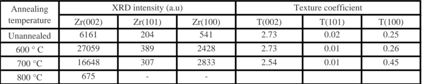
The texture coefficients values calculated for the zirconium phase are shown in the Table 2. They hardly change depending on the annealing temperature; T(002) has a value higher than one, while T(101) and T(100) have values close to zero. This shows that the films have a strong orientation in the (002) planes. For Zrα phase, which has a hexagonal structure, the (002) plane is the most compact and has the lower surface energy [18]. This indicates that the zirconium phase texture is always governed by surface energy minimization. The later conclusion confirms that the microstructure of deposited film is of zone II according to the structure zone model [17]. This confirms that high energy flux was impinging the growing film during the sputtering deposition of Zr. This result is coherent with other works where the (002) orientation is also observed for r.f. ion beam sputtering zirconium films deposited in a vacuum of 6.7×10⁻² Pa, on glass substrates (Ts = 200). However, a quasi-amorphous film was obtained when the deposition was performed at room temperature [25]. Recently, the same texture was reported for polycrystalline zirconium films of 1.2-1.5 μm deposited with a pulse power of 100 W, prepared by pulsed magnetron sputtering at room temperature. This orientation decrease slightly when the substrate temperature increases [35]. The texture of very thin polycrystalline zirconium films was studied as a function of thickness. The substrate temperature does not exceed 50 °C and the magnetron power was fixed at 118 W. The texture of the films is still (002), which is the densest plane parallel to the surface, for thicknesses between 12 and 180 nm. For 240 nm, a development of new fiber axis with majority of the grains having {109} planes parallel to the sample surface [18].
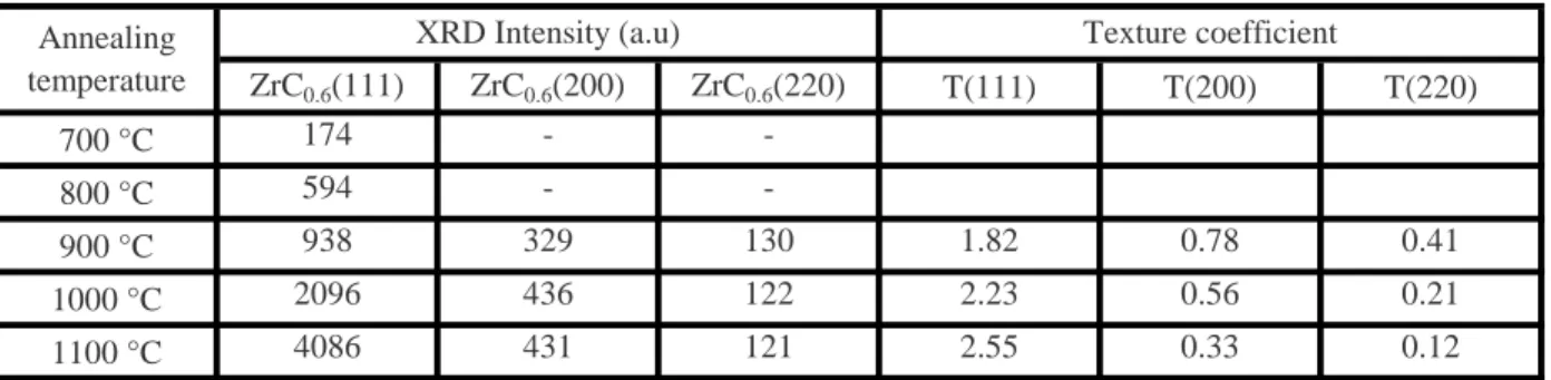
Table 3 shows the values of texture coefficients calculated for the zirconium carbide phase. At 900 °C, the calculated values of texture coefficients show an orientation according to the plan (111), but with a low degree compared to higher temperatures. This means that the carbide grains are almost randomly oriented but tend to orientate within the (111) planes. These observations show that the first carbide germs have almost random orientation, which is due to the fact that these germs begin to grow randomly on zirconium grain boundaries.
By raising the annealing temperature the degree of orientation to (111) plane, which is the more compact plane, became stronger to the detriment of the two planes (200) and (220). This texturation is due to carbide phase thickness increasing in the zirconium coating, and to the increase of the thermal stresses level induced by annealing, which implies that the mechanism that imposes the preferred orientation of carbide phase is the strain energy minimization. The same orientation is observed for nanocrystalline ZrC films deposited by sputtering with a DC power of 100 W deposited at 290ºC, which is attributed to more thermodynamic favorability [13]. The texture of
ZrC thin films deposited, at temperatures between 700 ºC - 850 ºC, by pulsed laser deposition has been studied. They grew along the [001] axis on (001) Si while they grew along the [111] axis on (111) Si and (001) sapphire [42]. In NaCl-type structure, the (200) plane has the lowest surface energy while the (111) plane has the lowest strain energy [43].
3.4. Mechanical properties
3.4.1. Surface mechanical properties
Mechanical properties of zirconium thin films are seldomly treated compared to films of zirconium carbides, nitrides, oxides, or even ternary compounds of the three. Carbon, nitrogen, and oxygen elements with zirconium are widely studied because of their excellent mechanical qualities.
The surface hardness of untreated zirconium film is about 7 GPa, Fig. 7. Recently, hardness values between 6.4 and 10.5 GPa have been reported for Zirconium films grown on Si(111) substrates by pulsed magnetron sputtering, at 500 °C and 300 °C, respectively [35]. This is in good agreement with our result. Our value is far above the value found in the literature for bulk zirconium of 0.84 GPa [10, 44, 45], this difference comes from the difference in microstructure between bulk zirconium characterized by large grains and the film consists of nanometer-sized grains in agreement with Hall-Petch relationship. During the growth, the zirconium film undergoes a particles bombardment, which contributes to the increase of the stress state and subsequently the film hardness.
From 600 to 800 °C, hardness increases with increasing annealing temperature. At 600° C, the XRD results do not indicate a significant formation of carbide in the film. We connect this increase in hardness to the improvement of film state after annealing, due to the organizing of the microstructure and reduction of structural defects, thus increasing the film compactness. However, the hardening observed at 800°C is caused by the formation of ZrC0.6 grains in the film.
From 900 to 1100 °C, despite the formation of stoichiometric carbide, the hardness drops a little, this can be attributed to the sample’s high microporosity (revealed by SEM) and the high surfaces roughness (Ra ~ 80 nm), which appears very steep, thus disturbing the measures and compromising measurement accuracy as the indenter size is small. This also, can be attributed to oxidation. It is known that zirconium oxide hardness is less than that of carbide [39, 45]. Therefore, zirconium oxide formation in zirconium carbide leads to a reduction in the overall hardness [22, 32, 46]. It has been reported that ZrC film hardness is lower for deposits made under residual vacuum pressure (<2×10⁻⁴ Pa) than for those deposited under CH4 atmosphere pressure (2×10⁻³ - 2×10⁻² Pa) [12].
The modulus of elasticity is a measure of material stiffness, it is about 140 GPa for surface of the unannealed sample, and this value is above the Young's modulus value of 98 GPa for bulk zirconium [44]. The variation of Young's modulus according to the annealing temperature follows exactly the same trend as the hardness, with 230 GPa at 1100 °C. Usually, E increases with the increase in rigidity due to the substitution of Zr bonds by more rigid C bonds (and even Zr-O).
3.4.2. Depth mechanical properties
The depth mechanical properties of the sample annealed at 900 °C are shown in the Fig. 8. The hardness values vary between 17 at the film interface and surface, and 13 GPa in the middle. The replacement of Zr-Zr bonds by stiffer Zr-C and Zr-O bonds caused the film hardening, a consequence of the carbide and oxide or even oxycarbide grains formation. This proves that the film middle zone contains less light interstitial elements than peripheral zones. This is in good agreement with our previous results. The formation of a second phase (carbide) adjacent to the parent phase (Zirconium), hinders dislocation motion also leading to the increase in hardness [47].
Furthermore, the maximum measured hardness (17 GPa) is low compared to the values reported in the literature for ZrC films deposited by different PVD methods. The values ranging between 26 and 36 GPa [13, 42, 48, 49]. This can be explained by the fact that the carbide phase that is formed for our films is mainly a substoichiometric phase (ZrC0.6), while the works found in literature deal with the stoichiometric phase. It is known that hardness is a function of carbon to metal ratio and that increases rapidly as it approaches the stoichiometric phase [38]. Likewise, D. Ferro et al. [50] have indicated that a decrease of carbon content can lower the hardness of refractory carbides with group IV elements (ZrC). On the other hand, this lower value can also be related to film contamination with oxygen (formation of oxide and oxycarbide phase). Given that the hardness of zirconium oxide is lower than the carbide, and the oxygen incorporation in ZrC crystal lattice would weaken the covalent character of the Zr–C bonding and favour of the more ionic character of the Zr–O bounding resulting in a decrease in the mechanical properties [30, 33].
The elasticity modulus values vary between 180 and 230 GPa. These values are smaller than values reported by several authors for zirconium carbide films, which vary between 325 and 450 GPa [13, 42, 44]. This is related to fewer Zr-C bonds in ZrC0.6 cell compared to ZrC [33].
The mechanical properties of the samples cross-sections are higher than those of films surfaces, which can be attributed to the difference in crystallographic orientation and grains alignment. The mechanical properties are anisotropic in nature and they heavily rely on structural parameters [1, 44].
The hardness of the substrate for the unannealed specimen is between 3 and 4 GPa. It remains in the same range after annealing between 600 and 800°C, in the contrary to the annealing at higher temperatures, 900 to 1100°C, where the hardness rises to values between 5 and 6 GPa, Fig.8. On the other hand, there is no observed significant decrease in the level of carbon signal at substrate in GDOES analyses after heat treatment in comparison to the pristine substrate, Fig.3. This indicates that there is no considerable carbon depletion gradient in the uppermost region of the substrates. These observations prove that the diffusing carbon atoms in the film does not result in the decreases in mechanical properties of the substrate.
The pristine substrate has a microstructure formed of ferrite and globular cementite, which indicates that the steel has undergone a spheroidizing treatment. This treatment is used to improve the ability to cold deformation of steel. It has a purpose to enhance the ability to use steels by making possible the application of high cutting speeds and insuring a very well state of surface.
By annealing an hypereutectoid steel (content of carbon is upper to 0,77 wt.%), when the temperature rises just above the eutectoid (727°C), the ferrite transforms to austenite by the diffusion of carbon from cementite grains. If the temperature continues to rise, the austenite may dissolve more carbon until a temperature slightly higher than 800°C, where all the ferrite and cementite are transformed in austenite. By cooling, the inverse phenomenon happens; the austenite transforms to pearlite and cementite. The pearlite is the heterogeneous mixture (aggregate) of ferrite and cementite. Consequently, the microstructure of steel changes from globular to lamellar cementite, this later microstructure is harder which results in the noticed rise of the substrate hardness values after the thermal cycle.
4. Conclusion
The evolution of the structural and mechanical properties of zirconium films deposited on C100 steel as a function of annealing temperature under vacuum was investigated. Results indicate a gradual transformation of the metallic film into zirconium carbide. The two phases coexist between 600 and 1000 °C. At 600 °C, zirconium phase is the predominant phase, but by raising the annealing temperature, the carbide phase becomes the major phase at 900 °C and remains the main crystallized phase at 1100 °C. This transformation is induced by the diffusion of carbon atoms from the substrate into the film. The results show also, the formation of ZrO2 on the surface for the higher temperature and a small amount of oxycarbide phase at intermediate temperatures could be expected. It seems that it is due to the higher reactivity of oxygen with zirconium than carbon. The measured lattice parameters (a and c) of Zr phase for the untreated sample are higher than the bulk parameters. They decrease after annealing due to stress relaxation, defects elimination and
atoms best rearrangement. The calculated lattice parameter for the carbide phase for the sample annealed at 800°C corresponds to the theoretical value of the substoichiometric carbide (ZrC0.6). After annealing, it rises continuously, showing the expansion of zirconium lattice due to the insertion of more carbon atoms. The lattice parameter calculated at higher temperatures is between the substoichiometric and the bulk parameters, which indicates the presence of the two phases. The grain size of both phases Zr and ZrC is in nanometrical order. Annealing leads to an increase in grain size for zirconium, they have always a strong orientation according to the plane (002). For ZrC phase, annealing does not affect the grains size, they are orientated within the (111) planes. The grains of carbide phase are present in the interface after annealing at intermediates temperatures, 600 to 900 ºC, while the rest of the film is composed of Zirconium grains. By rising annealing temperature, the growth of carbide grains displace progressively, across the film towards the surface.
The mechanical properties of the film are closely related to internal structure, density, structural defects and amount of phases present in the film: From the unannealed sample to the one annealed at 600 °C, the hardness rises from 7 GPa to 11 GPa. Simultaneously, Young's modulus changes from 140 to 170 GPa. The film consists of a single phase of zirconium and the hardening (despite larger grains) is caused by film densification and removal of defects. At 800 °C, the film is formed from Zr and ZrC0.6 grains. The hardness climbs to 14 and Young's modulus grows to 220 GPa. The improvement of film mechanical properties is related to the formation of harder and more rigid carbide phase. Diffusing carbons atoms from the substrate does not result in loses in the mechanicals properties of the substrate.
In order to achieve the whole conversion of the metallic film into stochiometric carbide with interesting mechanical properties, a longer annealing time at 900°C would be necessary.
References
[1] S. T. Oyama, The Chemistry of Transition Metal Carbides and Nitrides, Blackie A & P, First edition, London, UK, 1996, 535 p. [2] B. Navinsek, P. Panjan, A. Cvelbar, Surf. Coat. Technol. 74– 75 (1995) 155
[3] J. Brockner, T. Mantyla Surface and Coatings Technology, 59 (1993) 166—170 [4] J.-D. Gu, P.-L. Chen, Surface & Coatings Technology 200 (2006) 3341 – 3346
[5] I.A. Khan, S. Jabbar, T. Hussain, M. Hassan, R. Ahmad, M. Zakaullah, R.S. Rawat, Nucl. Instrum. Meth. Phys. Res. B 268 (2010) 2228. [6] E. Grigore, C. Ruset, K. Short, D. Hoeft, H. Dong, X.Y. Li, T. Bell, Surf. Coat. Technol. 200 (2005) 744
[7] A. OrjuelaG., R. Rincón, J. J. Olaya, Surface & Coatings Technology 259 (2014) 667–675
[8] Y.C. Kang, M.M. Milovancev, D.A. Clauss, M.A. Lange, R.D. Ramsier, Journal of Nuclear Materials 281 (2000) 57-64. [9] L. Pichon, T. Girardeau, F. Lignou, A. Straboni, Thin Solid Films 342 (1999) 93-99.
[10] G. Murtaza, S.S. Hussain, N.U. Rehman, S. Naseer, M. Shafiq, M. Zakaullah, Surface & Coatings Technology, 205 (2011), 3012–3019. [11] N. Ozkucur, C. Wetzel, F. Hollstein, E. Richter, R. H. W. Funk, T. K. Monsees, Journal of Biomedical Materials Research Part A. [12] D. Craciun, D. Craciun, G. Socol, N. Stefan, I.N. Mihailescu, G. Bourne, V. Craciun, Surface & Coatings Technology, 203 (2009), pp.1055– 1058.
[13] C.-S. Chen, C.-P. Liu, C.-Y.A. Tsao, Thin Solid Films, 479 (2005), p. 130–136. [14] K. Nakamura, M. Yashima, Materials Science and Engineering B 148 (2008) 69–72.
[15] J.A. Thornton, Annu. Rev. Mater. Sci. 7 (1977) 239. [16] P.B. Barna, M. Adamik, Thin Solid Films 317, 1998, 27–33.
[17] S. Mahieu, P. Ghekiere, D. Depla, R. De Gryse, Thin Solid Films 515 (2006) 1229–1249.
[18] J. Chakraborty, K. Kishor Kumar, S. Mukherjee, S.K. Ray, Thin Solid Films 516 (2008) 8479–8486. [19] B. Wendler, Materials Science and Engineering, A163 (1993) 215-217
[20] Y. Benarioua, J. Lesage, E. Bemporad, D. Chicot, Surface & Coatings Technology 200 (2006) 5447– 5454 [21] Y. Benarioua, R. Boubaaya, J. Lesage, D. Chicot, Surface & Coatings Technology 227 (2013) 65–69 [22] J. A. Rodriguez and P. Liu, PHYSICAL REVIEW B 72, 075427 (2005).
[23]E. Grigore, C. Ruset, X. Li, H. Dong, Surface & Coatings Technology 204 (2010) 1889–1892.
[24] K. Kato, T. Saito, S. Shibayama, M. Sakashita, W. Takeuchi, N. Taoka, O. Nakatsuka, S. Zaima, Thin Solid Films 557 (2014) 192–196 [25] S.-W. Yeh, T.-Y. Hsieh, S.-W. Mao, D. Gan, P. Shen, Mater. Chem. Phys. 105 (2007), p. 127–135.
[26] E. Silva, M. Rebelo de Figueiredo, R. Franz, R. Escobar Galindo, C. Palacio, A. Espinosa, S. Calderon V, C. Mitterer, S. Carvalho, Surface & Coatings Technology 205 (2010) pp.2134–2141.
[27] M. Kuhn, P.W. Gold, J. Loos, Surface & Coatings Technology, 177 –178 (2004), pp.469– 476. [28] D.F. Arias, Y.C. Arango, A. Devia, Applied Surface Science 253 (2006) pp.1683–1690. [29] J. Bloch I. Jacob and M.H. Mintz, Journal of Alloys and Compounds, 191 (1993) 179-186
[30] A. Bellucci, D. Gozzi, T. Kimura, T. Noda, S. Otani, Surface & Coatings Technology 197 (2005) 294–302.
[31] M. Dollé, D. Gosset, C. Bogicevic, F. Karolak, D. Simeone, G. Baldinozzi, J. Eur. Ceram. Soc., 27 (2007), p. 2061–2067. [32] V. Craciun, E.J. McCumiskey, M. Hanna, C.R. Taylor, Journal of the European Ceramic Society 33 (2013) 2223–2226. [33] M. Gendre, A. Maître, G. Trolliard, Journal of the European Ceramic Society 31 (2011) 2377–2385.
[34] Y. Katoh, G. Vasudevamurthy, T. Nozawa, L. L. Snead, Journal of Nuclear Materials 441 (2013) 718–742.
[35] A. Singh, P. Kuppusami, R. Thirumurugesan, R. Ramaseshan, M. Kamruddin, S. Dashb, V. Ganesan, E. Mohandas, Applied Surface Science, 257 (2011) 9909– 9914.
[36] F.Vaz, P. Carvalho, L. Cunha, L. Rebouta, C. Moura, E. Alves, A.R. Ramos, A. Cavaleiro, Ph. Goudeau, J.P. Rivière, Thin Solid Films, 469–470 (2004) 11–17.
[37] A. Singh, N. Kumar, P. Kuppusami, T.N. Prasanthi, P. Chandramohan, S. Dash, M.P. Srinivasan, E. Mohandas, A.K. Tyagi, Wear, 280– 281, (2012) 22– 27.
[38] L. E. Toth, Transition Metal Carbides and Nitrides, Academic Press, New York United States Of America, 279 p. 1971.
[39] H. O. Pierson, Handbook of Refractory Carbides and Nitrides, Properties, Characteristics, Processing and Applications, Noyes publications, New Jersey, USA, 1996, 340 p.
[40] K. Ashok, B. Subramanian, P. Kuppusami, and M. Jayachandran, Cryst. Res. Technol., 44, No. 5, (2009), p. 511–516. [41] J.P. Manaud, A. Poulon, S. Gomez, Y. Le Petitcorps, Surface & Coatings Technology 202 (2007) 222–231.
[42]A. J. Woo, G. Bourne, V. Craciun, D. Craciun, R. K. Singh, Journal Of Optoelectronics And Advanced Materials Vol. 8, No. 1, February 2006, p. 20 – 23.
[43] D. Roman, J. Bernardi, C. L.G. de Amorim, F. S. de Souza, A. Spinelli, C. Giacomelli, C. A. Figueroa, I.J.R. Baumvol, R. L.O. Basso, Materials Chemistry and Physics 130 (2011) 147– 153.
[44] E. A. Brandes, G. B. Brook, Smithells Metals Reference Book, Seventh Edition, Butterworth-Heinemann, Oxford, 1992.
[45] I.A. Khan, M. Hassan, R. Ahmad, A. Qayyum, G. Murtaza, M. Zakaullah, R.S. Rawat, Thin Solid Films, 516, (2008), p. 8255–8263. [46] M.M. Larijani, Sh. Norouzian, R. Afzalzadeh, P. Balashabadi, H. Dibaji, Surface & Coatings Technology 203 (2009) 2486–2489. [47] P. H. Mayrhofer, C. Mitterer, L. Hultman, H. Clemens, Progress in Materials Science 51 (2006) 1032–1114.
[48] D. Ferro, S.M. Barinov, J.V. Rau, A. Latini, R. Scandurra, B. Brunetti, Surf. Coat. Tech., 200 (2006), p. 4701– 4707. [49] D. Ferro, R. Teghil, S.M. Barinov, L. D’Alessio, G. De Maria, Materials Chemistry and Physics 87 (2004) 233–236.
Fig. 1: SEM images of Zirconium films surfaces, in SE mode: (a) untreated, (b) annealed at 900°C and (c) annealed at 1100°C.
Fig. 2: SEM images of Zr/C100 samples cross-sections: (a) untreated (SE mode), (b) annealed at 900°C (BSE mode) and (c) annealed at 1100°C (BSE mode).
Fig. 3: GDOES specters of Zr/C100 samples as a function of annaling temperature: (a) untreated, (b) annealed at 900°C and (c) annealed at 1100°C.
Fig. 4: XRD patterns of pristine Zirconium film (a), and vacuum treated at various temperatures, (b to e).
Fig. 5: XRD patterns representing the shifts of (111) peak of carbide phase by rising annealing temperature.
Fig. 6: Grains size evolution of the films as a function of annealing temperature.
Fig. 7: Variation of films surfaces mechanical properties according to annealing temperature.
Figure 1
Figure 2
Figure 3
Figure 4
Figure 5
Figure 6
Figure 7
Figure 8
Temperature (°C) 600 900 1000 1100
Thickness of film (nm) 3071 4140 3370 3480
Thickness of film inter-facial zone (nm) _ 580 870 1200
Thickness of film superficial zone (nm) _ _ 740 880
Thickness of film middle zone (nm) _ _ 1760 1400
Table 1: Thickness variations of different zones of zirconium film as a function of annealing temperature.
Zr(002) Zr(101) Zr(100) T(002) T(101) T(100)
Unannealed 6161 204 541 2.73 0.02 0.25
600 ° C 27059 389 2428 2.73 0.01 0.26
700 °C 16648 307 2833 2.54 0.01 0.45
800 °C 675 -
-Table 2: XRD intensities values of zirconium peaks (002), (100) and (101)
according to annealing temperature, and texture coefficients values of each peak.
Annealing temperature
XRD intensity (a.u) Texture coefficient
ZrC0.6(111) ZrC0.6(200) ZrC0.6(220) T(111) T(200) T(220) 700 °C 174 - -800 °C 594 - -900 °C 938 329 130 1.82 0.78 0.41 1000 °C 2096 436 122 2.23 0.56 0.21 1100 °C 4086 431 121 2.55 0.33 0.12
Table 3: XRD intensities values of zirconium carbide peaks (111), (200) and (200) according to annealing temperature, and texture coefficients values of each peak.
Annealing temperature
XRD Intensity (a.u) Texture coefficient