Analysis and Design of Electrochemically-Mediated
Carbon Dioxide Separation
by
Aly Eldeen 0. Eltayeb
B.S. Chemical Engineering, Cairo University, 2007
M.Sc. Chemical Engineering, Illinois Institute of Technology, 2010
M.S. Chemical Engineering Practice, Massachusetts Institute of Technology, 2011
SUBMITTED TO THE DEPARTMENT OF CHEMICAL ENGINEERING IN PARTIAL
FULFILLMENT OF THE REQUIREMENTS FOR THE DEGREE OF
DOCTOR OF PHILOSOPHY IN CHEMICAL ENGINEERING
AT THE
MASSACHUSETTS INSTITUTE OF TECHNOLOGY
.setemer2-
&
Crvne
'0om?]
C 2015 Massachusetts Institute of Technology. All rights reserved.
Signature of Author:
.Signature
redacted
Signature
Certified by:
5iT~p ent of Chemical Engineering
red acted
September
1 0 th,2015
lvT. Alan Hatton
Ralph Landau Professor of Chemical Engineering
Accepted
by:
Signature redacted
MA SSACHUSETTS INSTITUTE OF TECHNOLOGY
JUN 19
2017
LIBRARIES
ARCHIVES
Thesis Supervisor
Daniel Blankschtein
Professor of Chemical Engineering
Chairman, Committee for Graduate Students
Design of Electrochemically-Mediated Carbon Dioxide
Separation
By
Aly Eldeen 0. Eltayeb
Submitted to the Department of Chemical Engineering
on September 1
5th,2015 in Partial Fulfillment of the
Requirements for the Degree of Doctor of Philosophy
in Chemical Engineering.
ABSTRACT
Large-scale carbon dioxide (C0
2) separation is essential in the efforts to curb climate change, with
applications in power stations, natural gas purification and enhanced oil recovery. Current CO2
capture technology is energetically intensive, and challenging to deploy in existing power stations.
Electrochemical CO
2separation is a novel technology that has the potential to reduce C02 capture
costs. By cycling of metal ions to modulate the C02 affinity of amine sorbents, energy and capital
requirements can be significantly cut. The feasibility of this approach was previously demonstrated
with a proof-of-concept device, but was limited by low energy efficiency and instability. This
thesis describes a systematic effort to optimize this technology by exploring its design space, and
identifying conditions for robust, energy efficient operation.
The large effect of electrolytes on activation kinetics was explored via galvanostatic pulse
voltammetry and bench-scale experiments. In the presence of halide electrolytes, energy efficiency
was improved for short times, but bench-scale experiments showed an increase in resistance for
longer operation, possibly due to electrolyte inclusion in the metal deposit. For the set of the
electrolytes tested, nitrates were found to drive the most stable kinetics at moderate energy
efficiencies.
To explore the electrochemical cell performance for a range of designs and operating conditions,
a modeling framework combining thermodynamics, electrode reactions and mass transfer was
developed. Model predictions suggest the cell will operate in a mixed kinetic-mass transfer regime
at the desired current densities. Model results further predict that introducing flow field
disturbances to induce mixing between the bulk and boundary layer will improve energy efficiency
significantly.
A bench-scale system with modular internals was constructed and used to investigate performance
effects of flow field designs. Model predictions were found to be in good qualitative agreement
with experimental results. Under optimized conditions, an almost 70% lower voltage at 50 A/m
2was demonstrated. Electrochemical impedance spectroscopy experiments provide further evidence
to the mixed kinetics-mass transfer regime of operation. A detailed energy and cost analysis was
performed, and results suggest that this technology can cut capture costs significantly if the
performance improvement can be sustained for longer operation.
Thesis Supervisor: T. Alan Hatton, Ralph Landau Professor of Chemical Engineering
3-2011
-l
I
l
3
4-Acknowledgements
"Drinking from the firehose of knowledge" is a reasonable description of my overall MIT experience. I came to MIT driven by a desire to learn how science and technology can create impact in the world, and to then put that knowledge to practice. Along this journey way, I have been incredibly fortunate with the support, education, and help I received. There were many times, where this unwavering generosity carried the day, and for that I am infinitely grateful.
I am grateful to Professor T. Alan Hatton for my wonderful PhD experience in his lab. Throughout my
tenure, I left every progress meeting with Alan feeling energized, motivated and armed with an important learning. At every turn, Alan empowered me to pursue my intellectual curiosity and to develop personally and professionally, whether it was learning a new skill, diving deep into a domain, or getting first-hand experience in technology commercialization. Working with Alan taught me numerous lessons, but one stands out as a trademark of Alan's style: high quality and kindness frequently go hand in hand. I am grateful to have him as an advisor, a mentor, and a friend.
I am also grateful to my thesis committee members. Professor Bill Green posed key questions that strongly
shaped my research direction, and offered insights on the effect of additives on kinetics that were tremendously helpful. Professor Fikile Brushett's electrochemistry knowledge has been an invaluable resource, one that he generously made available. Howard Herzog's world-class expertise, and rigorous knowledge on the bigger picture of carbon dioxide capture taught me valuable lessons that will remain with me on the impact of policy on technology.
I am also grateful to all the members of the Hatton Lab: Demetra Achilleos for her mentorship on
experimental electrochemistry, and for sharing the struggle as a Mediterranean in Boston's winter; Mikhil Ranka for our creative work in deriving equations and documenting life lessons on lab windows, and for sharing a consistent curiosity about new technologies; Xiao Su for being our ChemE soccer coach, and for his inspiring enthusiasm for science; Lev Bromberg for sharing an office and having an incredible sense of humor; and Takuya, Paul, Wenda, Mao, Yinying, Sahag and everyone in the Hatton lab for many fun dinners, trips and valuable group meetings. I am also grateful to my talented UROPs: Hannah Capponi, Francesca Majluf, and Joanna Han.
I am also grateful for the access to other ChemE Faculty who made my experience richer. Professor Kristala
Prather played a central role in my MIT experience, and I am truly grateful to her for unwavcring support. Professor Martin Bazant offered a critical eye and important insights on modeling electrochemical flow. Professor James Swan helped me develop a framework to evaluate the impact of bubbles on electrode reactions. I am also grateful to Professors Hatton, Doyle, Brushett, Tisdale and Chung for their mentorship throughout my TA tenure. Through multiple TAing experiences, I had the opportunity to interact closely with ChemE class 18', and I will cherish this teaching experience going forward.
My ChemE cohort was a major source of delight, inspiration and, I hope, life-long friendships. Carl
Schoellhammer, Justin Kleingartner, Aditya Kunjapur, Mark Kiebler, Vik Adalstennson, Mark Molaro and my entire ChemE, thank you for all the fun times. I am also grateful to my larger ChemE family, particularly the ChemE soccer team for the friendship on the field and beyond.
The MIT Energy Club has been an integral part of my graduate school experience, professionally and personally. Josh Lehman taught me much about leadership, while generously allowing me to experiment
-with his nicknames. I am also grateful to Sergio Castellanos for an incredible team experience and for a friendship that spans thesis writing in Cambridge to urban explorations in Berkeley. I am grateful to Mustafa Ali, Akshar Wunnava, Onyeka Obassi, Ben Magolan, Libby Delucia, and many others in the Energy Club Community.
My life in Boston was beautifully colored by my Egyptian community. Amr Abdelbaki, Ahmed Magdy,
Rana Elkahwaji, Mohamed Zagho, Farida Mortada, Murad Alim, Youssef Sadeq and Tamer Elshayal: thank you for being home away from home. I am also grateful to my friends in Egypt for decades of a family-like friendship that keeps growing stronger: Zahran, Hesham, Hussein, Mohamed, Sherif, Monir, Zizo, Ibrahim, Karim, Ashraf, Hassan and Azmi.
I am also grateful for the friendship of my Sloan MBA class of 2017, with whom I shared many meaningful
experiences and wonderful adventures. Thank you for the opportunity to learn about the world through your diverse viewpoints, and for the inspiring moments throughout our experience.
Over the years, I have been blessed with mentors who have shaped my world view and offered me life changing opportunities. At the Illinois Institute of Technology, I had the privilege to be advised by Professor Fouad Teymour. His kindness, creativity and help inspired me to continue following my curiosity for science and technology. His many talents, as a writer and director, deeply impacted my view of what a full, multi-dimensional life means. On my first day at Cairo University, I accidentally walked into a lecture by Dr. Ahmed Gaber. By the end of it, I knew I will embark on a lifelong journey in Chemical Engineering. Dr. Gaber, thank you for being a mentor and role model, for teaching me how engineering can touch the
lives of millions, and for believing in me against significant odds -I am forever indebted.
To my family, thank you for the unlimited and unconditional love in the ups just as much as in the downs; for believing in me and supporting me through this journey; and for being a true north I could count on, always. Nermeen, Magdy, Seif, Omar, Amr and Yomna: I am incredibly lucky to have you in my life. To my father: your hard work, infinite curiosity and courage continues to inspire and challenge me to bring my best self to the world. Thank you, Baba for being my role model. Finally, to my late mother, a Chemical Engineering PhD, whose kindness and service set the highest standard for empathy, integrity and character.
I hope my efforts, plans and dreams, will make you proud.
-6-Table of Contents
1. Introduction...-
17
-Executive Sum m ary ...- 17
-M otivation ...- 21
-Carbon Dioxide Separation ...- 26
-EM A R Developm ent Challenges ...- 32
-Specific A im s ...- 37
-2. Electrochemical Kinetics under Additives ...-
38
-Additives and M etal Deposition and Dissolution Kinetics ...- 38
-Experim ental M ethods ...- 40
-Effect of Electrolytes on Com plexation Therm odynam ics ...- 48
-Effect of A dditives on Electrochem ical Kinetics ...- 50
-Bench-scale Experim ents ...- 53
-Data Fitting ...
56-M echanistic Analysis ...- 57
-Conclusions ...-
59-3. Cell Prototype Modeling Framework...-
61
-Electrochem ical Flow M odeling ...- 61
-M odel Overview ...- 63
-Species concentration distribution...- 64
-Initial and Boundary Conditions ... a... ...- 66
-EM AR Therm odynam ic Analysis ...- 67
-Electrochem ical K inetics...- 74
-7-Half-cell coupling ...
75-Bubble resistance ...
76-Solution Approach ...
78-M odel A ssum ptions ...
79-M odel Results ...
80-Conclusions ...
89-4. B ench-Scale P rototypes
...
91
-Prototype Components and Functions ... 91
-EM AR 4.0 - Previous Prototype Design ... 93
-Challenges with ENL4,R 4.0 ...
93-EM AR 5.0 - M odular Internals and Stable Configuration ...
96-EM AR 6.0 - M ulti-electrode Analytical Cell ...
98-EM AR 7.0 - High Pressure System ...
101-Peripherals ...
103-Autom ation ... 104
-Conclusions ... .
105-5. Bench-Scale Device Experiments
...
107-EM AR 5.0: Straight Channel Tests ...
107-Design Optim ization ...
115-Electrochem ical Im pedance Spectroscopy ... 122
-Role of M em brane ... 131
-EM AR 6.0 ... .133
-Conclusions ... .134
-6. P erform ance A nalysis
...
136
-M otivation and m ethodology ... 136-
-8-Energy Effi ciency ... . 137-Cost Estimation ... . 143-Conclusions ... .153
-7. Future D irections
...
155
-O v erview ... .155 -Optimization Targets ... . 156-Scale-up Demonstration ...159-Exploring Other Chemistries ...
160-Extension to Acid Gases ... 161
-8. C onclusions
...
164
-9. C apstone Paper
...
167
-Executive Summary ... . 167-Conclusions ... .194-10. R eferences
...
195
--9-List of Figures
Figure 1-1: Global land-ocean Temperature Index from 1880 till present. ...- 21
-Figure 1-2: Average atmospheric CO2 concentration, as measured by Mauna Loa Observatory ... 22
-Figure 1-3: US primary energy consumption by fuel, 1980-2040...- 23
-Figure 1-4: Schematic of CO2 Enhanced Oil Recovery ...- 25
-Figure 1-5: Summary of approaches to capture CO2 in power plants and industrial settings. ... 27
-Figure 1-6: Schematic of thermal amine scrubbing process...- 28
-Figure 1-7: Fluor's Econamine Process Flow Diagram...- 29
-Figure 1-8 Schem atic of the EM A R process ...- 31
-Figure 1-9: Cathode of proof-of-Concept device after a short duration of operation...- 33
-Figure 1-10: Electrochemical Capture Energy Consumption Profile...- 33
-Figure 1-11 shows a schematic of the electrochemical cell processes...- 33
-Figure 1-12: Schematic of Electrochemical Cell Processes ...- 35
-Figure 2-1: Current and potential as a function of time for a series of galvanostatic pulses from 1250 A/m2 to 12 5 A /m 2...- 43
-Figure 2-2: Equivalent Circuits. (Top): The equivalent circuit proposed to fit the charge resistance of the system. (Bottom): Simplified equivalent circuit used to fit pulse dynamics data to estimate kinetic p aram eters...- 44
-Figure 2-3: Short time response model fitted to experimental data for I M EDA, 0.25M copper nitrate and
IM sodium chloride at 55'C for three pulses (1250, 1000 and 500 A/m2)...-
45
-10-Figure 2-4: Dynamic pulse resistance values for IM EDA, 0.25M copper nitrate and IM sodium chloride
at 55'C, fit to the equivalent circuit model proposed, showing good agreement.. ...- 46
-Figure 2-5: Open circuit potentials for electrolytes in the presence and absence of CO2. ... . .. . . .. . . .- 49
-Figure 2-6: UV Spectra of Copper/EDA complex and free copper ions in absence of electrolyte...- 49
-Figure 2-7: Effect of Additives on UV-VIS Spectra. (Left): Copper/EDA complex. (Right): Uncomplexed
copp er ion s. ...- 50
-Figure 2-8: Effect of additives on EDA-complexed copper deposition and dissolution activation
overpotentials (Left): Under CO2. (Right): Under Argon. ...- 51
-Figure 2-9: Effect of temperatures from 25 - 75*C on the activation overpotential for EDA-complexed
copper deposition and dissolution activation overpotentials in KCl. (Left): Under Argon. (Right): Under
C 0 2...- 5 2
-Figure 2-10: Effect of temperatures from 25 - 754C on the activation overpotential for EDA-complexed
copper deposition and dissolution activation overpotentials in NaBr. (Left): Under Argon. (Right): Under
C O 2...- 5 2 -Figure 2-11: Applied potential difference change with time in NaBr electrolyte system tested at the
bench-scale. Solution consists of in I M EDA, 0.25M Cu(N03)2 and I M NaBr...- 53
-Figure 2-12: XPS results for bench-scale cell cathode with NaBr electrolyte. Solution: IM EDA, 0.25M
Cu(N 03)2 and IM N aBr at 55*C ...- 54
-Figure 2-13: Steady-state voltage-current density profile in NaNO3. Solution contained IM EDA, 0.25M
Cu(N03)2 and IM NaNO3 at 550C. ... ...- 55
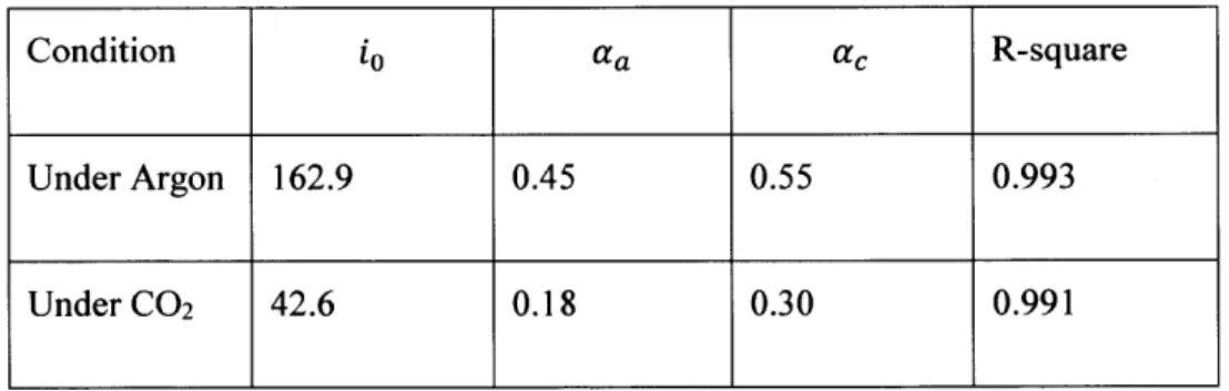
-Figure 2-14: EMAR anodic and cathodic kinetics under NaNO3 electrolyte, fit to the Butler-Volmer
equation. (R ight): A rgon. (Left):CO 2. ...- 57
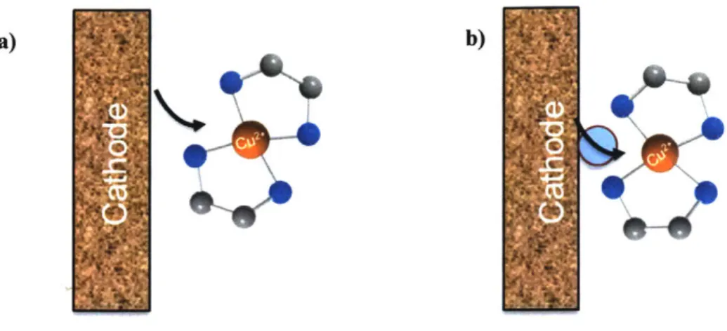
-Figure 2-15: Schematic contrasting two modes of charge transfer a) Outer-sphere b) Inner-sphere...- 58
-Figure 3-1: Schematic of model physics describing the two dimensional treatment of the two electrode
compartments to be dominated by a convective axial flow and a diffusive lateral flux...- 66
-Figure 3-2: Pourbaix diagram for copper/EDA system with EDA concentrations one order of magnitude higher than copper ion at 25'C, reproduced from work by Aksu and Doyle (52). Red dotted lines correspond to w ater splitting reactions...- 69
-Figure 3-3: Experimental measurement of EDA aqueous solution pH vs. CO2 loading, for a IM EDA so lution ...- 74
-Figure 3-4: Sample model run results. (Top): Current density and equilibrium potential. (Bottom): Anode activation overpotentials...- 81
-Figure 3-5: Sample model run results, showing the axial variation of laterally-averaged concentration of copp er ion s. ...- 82
-Figure 3-6: Sample model run results, showing the cathode concentration distribution along the lateral d irection . ...- 83
-Figure 3-7: Modeling predictions of effect of superficial velocity on polarization curves for flowrates betw een 75 - 300 m L/m in...- 84
-Figure 3-8: Model predictions of superficial velocity effect on axial variation of cell variables, for flowrates between 75 - 300 mL/min and 0.35V (kinetics-mass transfer controlled zone)...- 86
-Figure 3-9: Model predictions of superficial velocity effect on lateral distribution of copper concentration in the cathode compartment, for flowrates between 75 - 300 mL/min and 0.35V (kinetics-mass transfer controlled zone)...- 88
-Figure 4-1: EMAR 4.0 - previous generation of bench-scale cell prototype and system...- 95
-Figure 4-2: Clam ped prototype assem bly... - 97
-Figure 4-3: EMAR 5.0 - Photo of Assembled Cell ...- 98
12-Figure 4-4: EMAR 6.0: CAD sketches of design. (Top): Front view along an axial cross-section of unassembled cell. (Middle): Isometric view of cross-section along center axis of cell. (Bottom): Isometric view of an electrode segm ent...- 100
-Figure 4-5: EMAR 6.0 - Photograph of Cell. (Top): Assembled cell. (Bottom): Front view of
multi-electrodes held inside pockets in polypropylene layer...- 101
-Figure 4-6: EMAR 7.0 -High Pressure Prototype (Top): Sketch. (Bottom): Assembled Cell...- 103
-Figure 4-7: Bench-scale system with peripherals...- 103
-Figure 4-8: Bench-Scale Control Platform. (Top): Photograph of breadboard with control circuits.
(Bottom): Schematic of breadboard control scheme. ... - 105
-Figure 5-1: Straight Flow field used in initial EMAR 5.0 experiments. ...- 108 -Figure 5-2: Polarization curves for straight-flow channels with decreasing depths. (Top): Depth of 1/8". (Bottom): Depth of 1/16". Lines are for purpose of showing trends only. Experiments are at 55*C, IM EDA,
0.25M Cu(N0 3)2 and
IM NaNO
3... . . .. . . .. . . .. . . . .. . . .. . . . .. . . . .. . . .. . . . ..- 110-Figure 5-3: Effect of channel depth on polarization curves - comparing 1/16" and 1/8" channel depths under
the sam e flow rate...- 112
-Figure 5-4: Effect of channel depth at equal superficial velocity on polarization curves -comparing 1/16"
(blue) and 1/8" (maroon) channel depths at the same superficial velocity of 10.3 and 20.6 mm/sec. .- 113
-Figure 5-5: Flowrate vs. voltage. (Top): 1/8" depth channel. (Bottom): 1/16" depth channel. Experiments
are at 55'C, IM EDA, 0.25M Cu(N03)2 and IM NaNO3.... .. . . . .. . . .. . . . .. . . .. . . ..- 114
-Figure 5-6: Polarization curve for a 1/32" depth channel. Lines are for purpose of showing trends only.
Experiments are at 55'C,
IM
EDA, 0.25M Cu(N03)2 andIM
NaNO3.. . . . - 115-Figure 5-7: Model results contrasting straight and serpentine channel designs. (Left): Straight channel
design. (Right): Serpentine channel design ...- 117
-Figure 5-8: Samples of flow fields tested. a) Vertical serpentine arrangement. b) Short baffles perpendicular
to flow. c) Protruding baffles perpendicular to flow. ...- 118
-Figure 5-9: Cell anode post-operation hour using a long baffled channel, with removed layer...- 119
-Figure 5-10: Polarization curve for long baffled 1/16" depth channel...- 120
-Figure 5-11: Effect of temperature on performance in a 1/16" long baffle cell...- 121
-Figure 5-12: EIS results for EMAR 5.0 under static conditions...- 124
-Figure 5-13: EIS results for EM AR 5.0 w ith flow ... - 124
-Figure 5-14: Effect of flowrate on EIS results... ...- 125
-Figure 5-15: Comparing static and flow EIS results for 1/16" depth long baffle channel.. ...- 126
-Figure 5-16: Flowrate effects on EIS results for long baffle 1/16" depth channel...- 127
-Figure 5-17: EIS experiments centered around -0.lV vs. OCP for long baffle 1/16" depth channel...- 128
-Figure 5-18: EIS experiments centered around -0.1 V vs. OCP for long baffle 1/16" depth channel and higher flow rates...- 129
-Figure 5-19: Randles equivalent circuit utilized in analyzing EIS results...- 130
-Figure 5-20: Effect of membrane porosity on polarization curve in a 1/32" depth channel... ...- 132
-Figure 5-21: EIS testing of membrane porosity effect in a 1/32" depth channel. ...- 133
-Figure 5-22: Multi-electrode prototype bench-scale experiments; showing the change in current vs. axial location .. ...- 134
-Figure 6-1: Upper bound EMAR energy efficiency using Cu/EDA chemistry with nitrate electrolyte as function of current density...- 139
-Figure 6-2: Demonstrated bench-scale EMAR energy efficiency...- 140
-Figure 6-3: Ideal pumping and compression energy requirements for the electrochemical process operating
at different anode pressures...- 142
-Figure 6-4: Energy Efficiency Com parison...- 143
-Figure 6-5: Cost of energy as a function of energy consumption...- 149
-Figure 6-6: Membrane area required vs. current density...- 150
-Figure 6-7: Total cost of CO2 capture as function of energy consumption...- 151
-Figure 6-8: Sensitivity of CO2 capture cost to electricity price...- 152
-Figure 6-9: Sensitivity of capture cost to lifetime of project...- 153
-Figure 9-1: Breakdown of Current Demand for Utilization of CO2. ... . . . . .. . . . .. . . .. . . .. . .- 17 3 -Figure 9-2: Enhanced Oil Recovery with C02: high pressure gas is injected into the well, displaces the oil w hile reducing its viscosity.. ...- 174
-Figure 9-3: Enhanced Oil Recovery with C02: existing infrastructure in Gulf of Mexico area...- 175
-Figure 9-4: : A schematic depiction of the large-scale electrochemical CO2 capture process deployed dow nstream of a pow er station...- 180
-Figure 9-5: Point source CO2 Management Revenue Forecast. ...- 182
-Figure 9-6: Breakdown of stationary point-source production of CO2. ... . . . . .. . . .. . . .. . .. .- 183
-Figure 9-7: Breakdown of CO2 sources for utilization globally...- 184
-Figure 9-8: European Union Emissions Trading System Prices over the period 2006 - 2016. ...- 187
15-List of Tables
Table 1: Butler-Volmer parameters for the EMAR system under CO2 and argon with NaNO3 electrolyte.
Solution contained IM EDA, 0.25M Cu(N03)2 and IM NaNO3 at 55'C...- 56
Table 2: Values of physical parameters used in the simulations, for a temperature of 55'C... 79
-Table 3: Equivalent circuit fitted parameters for the 1/32" depth channel with flowrates of 75 and 150
m L /m in ...- 130
-Table 4: Comparison of EMAR with thermal and pressure-driven CO2 separation technologies- 189
-Table 5: M ajor U S CO 2Operators ...- 193
-16-Chapter 1
Introduction
Executive Summary
As the world population grows and standards of living improve, providing low cost energy to drive the global economy while addressing risks associated with climate change becomes more challenging. Current greenhouse gas emission rates from fossil fuel-based energy infrastructure run the risk of exceeding the
world's carbon budget, the limit for total emissions to keep atmospheric carbon dioxide (C02)
concentrations below levels predicted to cause significant climate change. The transition of energy generation infrastructure to renewable sources will occur over decades, exacerbating the climate change
challenge. This thesis focuses on developing a novel, electrochemical CO2 separation technology that has
the potential to allow for cost-effective energy from existing infrastructure at a fraction of emissions.
Cost-effective separation of C02, the most prevalent greenhouse gas, and its subsequent utilization or
sequestration, can open a path to a low carbon economy with existing energy infrastructure. However,
current technologies for CO2 separation suffer from low energy efficiencies and massive capital
requirements, which hinders their large-scale deployment beyond natural gas separations. Thermal amine
scrubbing, the defacto state-of-the-art CO2 separation technology, uses amine sorbents to reversibly bind
C02 molecules from gas mixtures, followed by a temperature swing to regenerate the sorbent and produce
a pure CO2 stream. Thermal amine scrubbing shows excellent performance with high selectivity and
durability, but requires massive amounts of steam for operation, limiting the technology's utility in capturing emissions from power plants and industrial sources.
Electrochemically-mediated Amine Regeneration (EMAR) technology offers an alternative approach to sorbent regeneration that can potentially cut capture costs significantly. The reversible binding of metal
17-ions with amine sorbents under a voltage swing was shown to effectively control the capture and release of
CO2. The process costs are intrinsically competitive: commodity materials, amine sorbents and copper
metal, are controlled by a targeted electrical current in a potentially high energy process that eliminates the
need for expensive modifications to existing CO2 sources for deployment.
A proof-of-concept device demonstrated the feasibility of the EMAR technology: copper ions generated at
the anode of a simple electrochemical cell strongly bind a polyamine sorbent loaded with C02, forcing gas
release and bubble formation, and at the cathode side of the cell, these copper ions were redeposited from
their polyamine complex, and the rate of CO2 generation was controlled by applied current.
This thesis provides a systematic exploration of the EMAR technology's design space, combining modeling and experiments to understand underlying processes and optimize process performance. The proof-of-concept device design suffered major limitations, resulting in energy consumption significantly higher than required for feasible operation. An analysis of the electrochemical cell performance suggests a significant opportunity for improvement by design optimization. The design space for the technology is vast, and requires a systematic effort to evaluate various energy contributions, a modeling framework to explore design parameters effects on performance, and high throughput experiments to test designs.
Chapter 2 is focused on the evaluation of possible electrolytes for the process, and their significant effects on stability and energy performance. Small-scale three-electrode experiments are used to explore the effect of electrolytes and their behavior as additives. Open circuit experiments supported by UV-VIS spectroscopy suggest electrolytes have no appreciable impact on copper/amine complex formation, and that their mechanism of action is kinetic in nature. Galvanostatic pulse experiments are used to probe the activation overpotentials at various current densities for a set of electrolytes. Results demonstrate a significant change in behavior under EMAR anodic and cathodic conditions. Bromide salts are found to reduce activation overpotentials, while nitrates and chloride salts show a slower but reasonable performance. Bench-scale testing of bromide salts finds their enhancement effect to subside quickly. XPS analysis of the formed copper deposit suggests that the electrolyte is co-deposited and is possibly causing an increase in contact
18-resistance. Nitrate salts are found to have more stable performance, and are utilized in further studies. A mechanistic discussion suggests that electrolytes act to modulate activation overpotentials by acting as ligand-bridges for an inner-sphere electron transfer mechanism. Further screening of a larger set of electrolytes guided by this hypothesis is recommended.
Chapter 3 develops an analysis of the effects of design and operating parameters on the electrochemical cell performance. A two dimensional modeling framework is built to explore those effects, tracking the copper ion concentration in each electrode compartment. Electrochemical thermodynamics are modelled through the Nernst equation, and activation kinetics are represented by the semi-empirical Butler-Volmer equation with experimentally derived parameters. Ohmic losses are modeled by a linear solution and contact resistance measured using Electrochemical Impedance Spectroscopy. Bubble overpotentials are included through an estimate of their electrode blocking effects. Half-cell coupling is achieved through a constraint on applied voltage distribution. The system equations are solved numerically, and a parametric study is performed. Model predictions suggest large mass transfer limitations, manifesting in a large difference in concentration at the electrode surface and in the bulk and a thick boundary layer. Higher superficial velocities, through smaller channel depth and higher flowrates, will improve mass transfer and lower thermodynamic penalties, but result in lower utilization. The design rules inferred from modeling
predictions are used to guide prototype optimization.
Chapter 4 critically assesses the current EMAR cell design, and discusses design improvements aimed at
facilitating high throughput design testing and stable operation. An upgraded modular design, EMAR 5.0,
is designed and constructed with the purpose allowing rapid design changes and tests. A multi-electrode prototype, EMAR 6.0, is developed to allow spatial resolution of current distribution and allow further probing of internal cell processes. Finally, a high pressure operation prototype, EMAR 7.0, is designed as
a step towards demonstrating the technology's ability to capture and release compressed CO2 by pumping
the electrochemical cell to higher pressures.
19-Chapter 5 explores the performance of bench-scale prototypes designs through their polarization curves and electrochemical impedance spectra. Parametric studies of channel depth and operating flowrate effects qualitatively confirm model predictions, and show high energy efficiency for maximized superficial velocity. Experimental trends suggest cell operation at desired current-densities is in a mixed mass-transfer/activation control regime. To limit the loss of utilization for higher superficial velocity, an optimization strategy utilizing serpentine flow fields is tested. Modeling predictions suggest that efficient remixing of bulk and surface streams inside the cell will improve performance significantly. Serpentine flow fields are tested, and shown to successfully improve energy efficiency, demonstrating a record 30
kJ/mole CO2 captured at a current density of 50 A/m
2
. Electrochemical Impedance Spectroscopy experiments at the bench-scale provide further evidence on the mixed regime operation of the process, and the effect of flowrate on performance. A short-study of membrane effects suggests an important effect of membrane pore size on performance, indicating a potential electrolyte migration effect can be important, particularly at higher current densities.
Chapter 6 serves to combine the modeling and experimental results into a holistic performance analysis of the EMAR technology. Energy performance and capture costs are analyzed for an upper bound scenario assuming no mass transfer limitations, and a scenario building on bench-scale results. The analysis finds that the EMAR process, if long stable operation is feasible, can potentially cut capture costs significantly.
A sensitivity analysis shows that the cost structure is most sensitive to energy costs and project lifetime.
Chapter 7 provides an outlook of the EMAR technology, and the major priorities for further research and development. Optimization targets for the current prototype generation are outlined. A scaled-up version of the cell to demonstrate cell stacking is discussed. Exploration of other promising chemistries and extension to other Sulphur acid gases are also proposed. Chapter 8 reiterates the main conclusions of this work, and Chapter 9 complements it with a financial and business analysis of industrial deployment contexts and a potential go-to-market strategy.
-The remainder of this chapter provides a more detailed motivation for cost-effective CO2 separations technology, analyzing the climate change challenge and the role of existing energy infrastructure. A short discussion of existing CO2 separation technologies contrasts the state-of-the-art with the potential
advantages of the EMAR technology. An analysis of previous EMAR development efforts serves to bring context to the work performed in this thesis, and to outline its guiding methodology.
Motivation
Climate Change and Carbon Dioxide
Climate change is one of the most critical global challenges in the 2 1st century. Scientific consensus on the
effect of anthropogenic carbon dioxide emissions on climate change is strong. Numerous studies and reports, including by the Intergovernmental Panel on Climate Change (IPCC) (1) and the National Academy of Sciences (2), critically compiled and assessed scientific evidence and concluded that greenhouse gas emissions from human industrial activity are the main driving force for climate change (3).
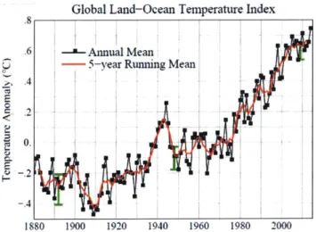
Since 1970, the rate of global temperature increase has nearly tripled from pre-industrial rates, to 0. 160C per decade (4). Figure 1-1 shows historical mean temperatures by the National Aeronautics and Space Agency (NASA), demonstrating a clear upwards trend.
Global Land-Ocean Temperature Index
.8
.6 Annual Mean - 5-year Running Mean .4
E
LV 0.
1880 1900 1920 1940 1960 1980 2000
Figure 1-1: Global land-ocean Temperature Index from 1880 till present. Data by NASA's Goddard Institute for Space Studies, reproduced from (5)
-21-Greenhouse gases, like C02, accumulate in the atmosphere and alter the earth's ability to undergo radiative cooling, gradually causing changes in surface and ocean temperatures (6), thought to be irreversible (7). Major climate changes include change in extremes in temperature and precipitation, increase of sea levels (8) and water CO2 concentrations, and many other secondary effects (9). Atmospheric CO2 concentration
has risen from 280 ppm before industrialization and reached 400 ppm in May 2013; Figure 1-2 shows the historical trends. Anthropogenic CO2 emissions from energy infrastructure and industrial activity are the
major driver for this increase in CO2 concentration (10).
120 40 100 30 E 140 20 .10 20 0 Prekosla value: 280 ppm 10 1980 1990 2000 2010
Figure 1-2: Average atmospheric CO2 concentration, as measured by Mauna Loa Observatory, Hawaii. Figure reproduced from data the National Oceanic and Atmospheric Administration (NOAA).
Continued increase in global temperature and climate change at current rates is predicted to have a massive negative global impact (11). Agricultural yields are predicted to be dramatically affected. For example, corn and soybeans production in the United States which currently account for about 40% of the world's production of these crops, can fall by up to 30%-50% under the slowest warming scenario (12). A potential increase in the frequency of occurrence of extreme weather events, like hurricanes, floods and droughts, will result in massive economic losses (13). Overall ocean acidification due to CO2 absorption, around 0.1 pH unit since preindustrial periods, will significantly reduce aquatic diversity and disrupt marine ecosystems (14).
-Energy Infrastructure and Emissions
Thus, significant reduction in carbon emissions, primarily from fossil fuels, is necessary to avoid the adverse effects of climate change (15) (16). However, current global energy infrastructure is dominated by fossil fuels, and various outlooks and analyses predict that a shift to renewable energy will require several decades to occur (17) (18). The US Energy Information Administration (EIA) outlook predicts that by 2040 fossil fuels will continue to supply more than 75% of the US primary energy needs (19).
120 100 80
60
40 20 0 1980 1990 History 2013 Projections 1990 2000 2013 2020 2030 2040Figure 1-3: US primary energy consumption by fuel, 1980-2040. Reproduced from (19).
For example, coal-fired power plants, responsible for 40% of US missions (20), will remain an important component of electricity production, and are projected to account for 38% of electricity generation in 2035
(21). At current emissions levels, the 20C threshold for global temperature increase (the limit predicted to
precede massive climate change effects) will be exceeded.
Carbon Capture and Sequestration
Emissions from existing infrastructure must therefore be addressed in the interim period as the global energy infrastructure transitions to low emission sources. To that end, carbon capture and sequestration
-(CCS) is a critical component of environmental policy aimed at curbing greenhouse gas emissions in the
next few decades (22). Analysis by the International Energy Agency predicts that over 100 GW of
coal-fired power plant capacity must be retrofitted with CCS to achieve climate change mitigation objectives
(23). The IPCC report on CCS provides a detailed analysis of the importance and feasibility of this approach in contributing to the transition to a low carbon economy (24).
CCS relies on cost-effective separation of CO2 from flue or industrial gases, compression (to around 150
bars) and transport via pipeline to a sequestration site. Sequestration can also involve transformation, and
a growing body of literature exists for development of technologies to convert CO2 to higher value products,
including reduction to carbon monoxide, methanol and formate among other target molecules (25) (26). However, given the billions of tons of C02 that must be sequestered, larger-scale approaches are necessary, as the markets for high value-added chemical can quickly become saturated with the massive possible
amounts of CO2 based products. Sequestration of captured CO2 into deep saline aquifers is feasible in terms
of scale (25), but economically challenging without significant government subsidies.
A more economically feasible approach is the sequestration of CO2 in mature oil fields. The pressurized
gas can serve to extract large volumes of oil from existing oil fields at a competitive cost. Figure 1-4 shows
a schematic of the process. Supercritical CO2 injected into a mature oil reservoir becomes miscible with oil.
A component of the injected CO2 dissolves in the crude, reduces its viscosity and increases its flow, but the
majority of the gas remains in the oil reservoir (26).
The subsequent combustion of oil implies the substitution of higher carbon-footprint from traditional
reservoirs with oil from CO2 EOR, cutting the carbon footprint of oil by more than two-thirds (27). CCS
coupled with enhanced oil recovery (EOR) can sequester massive amounts of CO2 by producing low carbon
footprint oil using existing infrastructure (28).
-Prdw~ WW
"N"wa
-I- i-T
hec.;Iad O3 W2 A"d Od eq dardsrM W *Nw" 6"4d ON1A M~ i d01ih pmd. ,A
Figure 1-4: Schematic of C02 Enhanced Oil Recovery. Figure reproduced from US Department of Energy's Office of Fossil Fuels (http://energy.gov/fe/science-innovation/oil-gas-research/enhanced-oil-recovery)
CO
2Separation in Natural Gas Purification
In addition to being a centerpiece technology for CCS applications, separation of CO2 from gas mixtures is
important in a number of other contexts that are worthwhile to outline briefly. The most prominent application is in natural gas purification, where the acid gas must be removed before natural gas is transported by pipeline or in liquefied form, to avoid corrosion and solid formation, respectively. This application has been historically the driving force for the inception and development of carbon dioxide separation technologies. Today, a large number of commercial scale plants exist to purify natural gas by
removal of CO2.
-Carbon Dioxide Separation
The previous section outlined the necessity for addressing the climate change challenge, and the importance of minimizing greenhouse gas emissions from existing energy infrastructure, as we transition to a renewable energy world. In this section, we further motivate this thesis by briefly analyzing existing carbon dioxide separation technologies and their limitations.
The CO2 separation challenge involves developing means to effectively remove CO2 from associated gas
mixtures with the highest selectivity, and deliver it in a pure form for further use, sequestration, or venting (in natural and fuel gas applications). The most relevant gas mixtures are coal-fired power plant flue gases
where CO2 concentration is between 0.12 and 0.15 on a molar basis. For gas-fired flue gas, CO2
concentration is in the range of 0.05 molar. Other important gas mixtures include natural gas, where CO2
concentrations range from less than 1% by volume, to more than 20% for reserves in Malaysia and Indonesia.
From a thermodynamic perspective, separating CO2 from a gas mixture can be thought of as a de-mixing
process, where the entropy of an ensemble of molecules system is reduced, and thus a net energy input is required to drive this separation.
The fundamental energy consumption limit for CO2 separation is the Gibbs free energy arising from the
entropic penalty of separating a gas into its components, which can be computed as:
Wuim = RT Exi in xi
where R is the Universal Gas Constant, T is the operating temperature and xi is the mole fraction of gas.
For coal-fired power plant flue gas, this penalty amounts to 7-9 kJ/mole CO2 captured. This presents a lower
bound for energy consumption for any CO2 separation process.
A number of different approaches for carbon dioxide separation in power plants and industrial settings have
been developed, and are summarized in Figure 1-5. Pre-combustion and oxyfuel are promising approaches,
-but relevant only in the case of new power plants, as they require fundamental modifications to the
combustion and power generation processes. Post-combustion capture is an approach where CO
2is
separated from flue gas after oxidation in a boiler and power generation, and is the most promising approach
relevant to CCS applications.
N2 02 coalcPost combustion
Ga
AirC2Pre combustion GasIf0on RefoNu & N202
a 00aSsN"
Oxyfuel & P tow
Maro -- O"T eato
Industrial processes
an0Raw nintsrbl G0. Ammronia. Stot
Figure
1-5: Summary ofapproaches
tocapture
C02in power plants and industrial settings. Reproduced
from (24)Many post-combustion technologies are in development, and can be categorized according to the separation
mechanism to thermal swings, pressure swings and membrane separation. Thermal swing technologies, the
most prevalent category, involve capturing CO
2chemically by a sorbent molecule that undergoes a large
change in its C02 affinity
between
two temperatures. At the absorption temperature, the sorbent readily
takes up CO, from a gas mixture, and subsequently releases CO
2at a higher desorption temperature. From
a molecular perspective, a thermal swing relies on an increase in entropic effects with higher temperatures
to dominate enthalphic interactions. Pressure swing processes rely on a large change in partial pressure of
CO
2to force the gas into and out of a capture material, through a physical or chemical mechanism.
Membrane processes utilize materials with high CO
2selectivity and reduced permeability for other gases
-27
to capture a pure gas stream from a pressurized mixture. A large number of candidate sorbents and processes have been developed and proposed, and a full review is outside the scope of this work. The interested reader is directed to a number of comprehensive reviews (31) (32) (33) (34).
The state-of-the-art technology in CO2 separation for CCS applications is by far thermal amine scrubbing, a technology that has been commercially deployed since before mid-201 century, as early as 1930 (35) (35). Since then, the technology has witnessed wide-scale deployment in the natural gas industry and in refineries across the world, due to its ability to generate CO2 streams of high purity and remove the gas from mixtures
to the very low specifications required for natural gas transport. A molecular schematic of the process is shown in Figure 1-6. Due to their basicity, amines have a high affinity for the weakly acidic CO2, and together they form a stable complex that is dissociated at high temperature to release pure CO2 and regenerate the amine solvent.
Amine
Cool
4
Amine/CO
2Complex
Heat
Amine
Figure 1-6: Schematic of thermal amine scrubbing process
At the process scale, thermal amine scrubbing benefits from decades of equipment optimization, commercial operation and in-depth modeling, and is thought to be rapidly approaching its performance
-28
-Co2
Co2
limits. Proprietary processes have been developed by many companies including Fluor, Alstom, Siemens, and Mitsubishi, differing primarily in capture agent solution. Figure 1-7 shows an example process flow diagram, featuring Fluor's Econamine process. In a lower temperature absorber, lean amine is contacted
with flue gas to enable CO2 capture. The C02-bound amine then goes to a high temperature stripper, where
an entropic driving force facilitates solvent regeneration and the release of a pure CO2 stream.
Thermal amine scrubbing technology, however, suffers high costs of capture in CCS contexts, especially in retrofit applications (29). This high cost is the result of large energy consumption that significantly derates the power plant electrical output, and high capital cost associated in part with power plant modifications required to enable extraction of low pressure steam for the stripping operation (30) (31). In addition, deploying thermal amine scrubbing in high emission industrial settings where steam is not readily available, such as steel, aluminum and cement plants, presents a further challenge and requires dedicated steam generation equipment.
Thus, a novel post-combustion technology that combines the excellent removal and durability properties of thermal amine scrubbing with electrically-driven operation at high energy efficiency would present a powerful combination and promising approach.
r - 1PRODUCT CO,
aRBER VEN T
Figure 1-7: Fluor's Econamine Process Flow Diagram
-Electrochemically Mediated Amine Recovery (EMAR)
We recently proposed a novel approach to C02 capture that has the potential to significantly improve the economics of CCS. This approach, Electrochemically-Mediated Amine Regeneration (EMAR), is an
electrically-driven, highly targeted approach to CO2 capture that does not require large-scale steam
extraction or any expensive power plant modifications. Instead, the EMAR process utilizes redox
responsive metal ions to modulate the affinity of amine solvents for CO2 by competitive complexation. The
steam-free nature of the EMAR process eliminates the need for expensive retrofits, and provides for a plug-and-play, drop-in solution. In addition, due to its more targeted nature and ability to operate under high liquid pressures, the electrochemical approach can potentially be more energy efficient than thermal stripping options.
The EMAR technology replaces thermal stripping operation in an amine-based CO2 flue gas scrubbing
process, and relies on almost isothermal electrochemical cycles rather than the large temperature swings required in conventional absorption/stripping processes. In the stripper, the C02 is released upon the acidification of the absorbent stream through the oxidative addition of Lewis acid transition metal cations
from a metal anode. Once the released CO2 is removed, the amines themselves are regenerated for recycle
to the absorber by reduction of the metals on electrode surfaces in a cathode chamber, recycling the metal. The flow directions and the polarity of the two electrodes are switched after a period of time to maintain the integrity of the electrodes.
A previously tested EMAR chemistry uses a polyamine solvent to capture CO2 from flue gas in an absorber
operating at a relatively low temperature. To regenerate the solvent and provide a pure stream of C02, the
C02-loaded polyamine solution is pumped to the anode side of an electrochemical cell, where copper ions are generated by electrochemical dissolution. The copper ions formed chelate strongly with the polyamine
molecules, releasing CO2 in the form of gas bubbles by a competitive complexation mechanism. The CO2
gas is flashed off at the exit to the anode chamber. After the gas bubbles are removed, the copper-loaded amine solution is recycled to the cathode side of the electrochemical cell. At the cathode, copper ions are
-30-removed from their amine complex by electrochemical deposition. The lean amine solvent is then pumped to the absorber where it performs further separations. The cycle is described schematically in Figure 1-8.
CO
2Remove
CO
2Amine
A++
Amine/Metal
Complex
Amine/CO
2Complex
Add M**
0
Figure 1-8 Schematic of the EMAR process, showing the competitive complexation of the amine solvent by meta ions formed by electrodissolution, followed by removal of metal ions by electrodeposition. There are several advantages to the EMAR process:
1. Direct targeting of electroactive metal ions that modulate amine/C02 affinity results in higher
energy efficiency, in contrast to thermal cycling where significant entropic losses occur as heat is added to the entire medium.
2. Due to the electrically-driven nature of the EMAR process, integration with existing CO2 sources
is straightforward, eliminating the need for expensive retrofits to deliver steam.
3. The electrochemical cell can potentially operate at high pressures, with the CO2 released as a
compressed gas. In the context of power station emissions, captured CO2 needs to be compressed
to around 150 bars to facilitate transportation to a final sequestration site. Since the pumping of a liquid to raise the pressure is significantly more energetically favorable than the compression of a
-31-Metal
gas, high liquid pressure operation of the EMAR process can result in significant savings in
downstream compression requirements (32).
With a focus on copper metal and polyamines, previous development work showed that the thermodynamics of electrochemically-controlled copper-amine complexation can be energetically efficient and highly favorable. The electrochemical kinetics of copper ion formation and subsequent deposition from its amine complex were studied experimentally for a range of polyamines, and shown to be most facile with ethylenediamine (EDA) (34). A proof-of-concept system was developed and demonstrated, with sustained
control of CO2 capture rate with cycling of electric current (33). There remains, however, a number of
challenges that must be addressed to develop the EMAR technology further.
EMAR Development Challenges
Early proof-of-concept prototypes were successful in demonstrating the feasibility of the EMAR technology. Fundamental thermodynamic analysis and open circuit experiments for the EMAR system using copper/ethylenediamine chemistry predict high efficiencies that have the potential to significantly change the economic feasibility of large scale CCS in power stations. However, the proof-of-concept prototype operates at significantly lower energy efficiencies than economically feasible for large-scale applications. In addition, the prototype features dendrite formation and transport limitations at high flowrates. Figure 1-9 shows a post-operation cathode for the proof-of-concept system, where copper deposition is on top of a cloth covering the cathode and meant to support the separator. The resulting uneven deposition of copper powder on top of the fabric lead to dendrite formation and caused short-circuiting of the cell.
-32--p
Figure 1-9: Cathode of proof-of-Concept device after a short duration of operation. The electrode surface is covered with a fabric covered in deposited copper to prevent collapse of separator onto electrode. Such a design imposes a significant limit on stability: Reproduced from (34)
Figure 1-10 shows the current proof-of-concept system energy consumption compared with the thermodynamic limit of the process, based on open circuit potential measurements. The thermodynamic
energy penalty using copper/EDA chemistry is only around 15 Id/mole C02; however, the proof-of-concept
device operates at around 100 kJ/mole at a moderate current density of 50 A/m2.
Economic Feasibility
Prototype
-100 kJ/mole 0Minimum
-10-15 kJ/mole S | I I I I 0 20 40 60 80 100 120 Capture Energy (kJ/mole)Figure 1-10: Electrochemical Capture Energy Consumption Profile. Proof-of-concept device consumes more than 100 kJ/mole CO2 at 50A/m2, significantly higher than the minimum thermodynamic penalty for the
EMAR process, 10-15 kJ/mole. The estimated limit for economic feasibility is around 55-65 kJ/mole.
Bridging the performance gap between the working prototype and theoretical predictions is critical to the continued development of the EMAR process and in bringing it closer to commercial application. It is instructive here to analyze the major processes occurring in the electrochemical cell to understand potential sources of energy inefficiencies and the methodology applied in this work.
Figure 1-11 shows a schematic of the electrochemical cell processes. At the anode side, copper ions are
-formed by electrodissolution at the electrode, and must diffuse to the bulk to react with the aqueous C02 -loaded EDA solution according to the reactions:
Cu -> Cu+2 + 2e (1-1) Cu2
+ + 2EDA. CO2 -> Cu2+(EDA)2 + 2CO2 (1-2)
The first reaction is thought to occur through a two-step mechanism and to be charge-transfer controlled. The second reaction is much faster, due to the large driving force offered by the strong chelation between
copper and EDA. As the dissolved CO2 concentration increases above supersaturation levels, bubbles form
spontaneously and are entrained with the flow. The anode outlet solution thus consists of a two-phase mixture with the aqueous phase containing both C02-loaded and copper-loaded EDA. Gas bubbles are disengaged in an external flash tank, and the aqueous solution reenters the cell at the cathode side. Copper/EDA complex ions must diffuse to the electrode surface where copper is deposited on the surface as per the reaction:
Cu2+(EDA)
2 + 2e- -+ Cu + 2EDA (1-3)
Finally, the regenerated EDA solution is sent to the absorber to once again be available to bind CO2.
-34-
V-$1
To Absorber
- 0-Co2Bubbles
000so.
0
0*
T
From Absorber
Figure 1-12: Schematic of Electrochemical Cell Processes
For a perfectly reversible thermodynamic process, the major energy penalty in this process is the EDA/CO2
decomplexation energy, since other reactions in the system are reversible and, theoretically, no net change in copper ion concentration should occur at steady state. However, additional thermodynamic losses due to Nemstian concentration terms (i.e. copper concentration differences between the two electrode compartments) occur, as discussed in detail in Chapter 3.
The electrochemical reactions at the anode and cathode will also require an energy input (an activation overpotential) to drive the large currents necessary for industrial operation. As the current density is ramped up, reactant and product concentration profiles will develop, changing the surface concentrations and, consequently, the thermodynamics and kinetics of the process.
The system and cell design parameters can have major nonlinear effects; the flow field (planar in the proof-of-concept device), electrolyte and membrane choices will affect mass transfer and thereby change the
-35-I ~ ~. A A ~ ~' 1
P
*1/ V ;~.mm--V-thermodynamic and kinetic behavior of the cell. Operating conditions, like temperature and flowrate, will change the solution properties, including conductivity and viscosity.
Methodology
The energy performance of the EMAR system is the nonlinear product of thermodynamics, kinetics and mass transfer properties of the system. The large number of design decisions, including selection of electrolytes, cell flow field and operating conditions, requires a systematic framework to evaluate these choices. The focus of this work, therefore, is to develop a consistent methodology to evaluate energy sinks and their underlying mechanisms, and to link them with the design space. Through a systematic investigation of parameter effects, guided by a modeling framework, the optimization of process energy consumption and stability can be addressed.
The Cu/EDA chemistry demonstrated efficient thermodynamic energy needs, with a minimum energy of less than 15 kJ/mole and compares favorably to the fundamental entropic limit of 7-9 kJ/mole. In addition, Cu/EDA chemistry has a linear behavior at a range of loadings, with stable complexation properties that are conducive to effective operation. For those reasons, this chemistry is used throughout this work, with recommendations for future work to evaluate other potential sorbents. The electrochemical kinetics of copper, and indeed of many metal ion systems, is a strong function of the electrolyte utilized. A logical starting point for this work is to explore this effect, and identify optimum electrolytes that drive stable and energy efficient kinetics. This is explored in Chapter 2, using both small-scale experiments to isolate and quantify activation kinetics, followed by larger bench-scale experiments to evaluate performance at longer time scales.
Building on models of thermodynamics (guided by a Pourbaix diagram for the Cu/EDA system) and kinetics, a cell modeling framework is then developed to improve our understanding of how the electrochemical reaction rates are coupled with flow and mass transfer. Chapter 4 develops this framework, and numerical solution to the developed model with a parametric study of major cell design and operating