HAL Id: hal-02416244
https://hal.archives-ouvertes.fr/hal-02416244
Submitted on 17 Dec 2019
HAL is a multi-disciplinary open access
archive for the deposit and dissemination of sci-entific research documents, whether they are pub-lished or not. The documents may come from teaching and research institutions in France or abroad, or from public or private research centers.
L’archive ouverte pluridisciplinaire HAL, est destinée au dépôt et à la diffusion de documents scientifiques de niveau recherche, publiés ou non, émanant des établissements d’enseignement et de recherche français ou étrangers, des laboratoires publics ou privés.
Uncertainty assessment on the prediction of the CABRI
power transients
O. Clamens, P. Blaise, Jp. Hudelot, J. Lecerf, B. Biard
To cite this version:
O. Clamens, P. Blaise, Jp. Hudelot, J. Lecerf, B. Biard. Uncertainty assessment on the prediction of the CABRI power transients. PHYSOR 2018 - Reactor Physics paving the way towards more efficient systems, Apr 2018, Cancun, Mexico. �hal-02416244�
UNCERTAINTY ASSESSMENT ON THE PREDICTION OF
THE CABRI POWER TRANSIENTS
Olivier Clamens1, Patrick Blaise1, Jean-Pascal Hudelot1, Johann Lecerf1, Bruno Biard2
1CEA, DEN, CAD/DER/SPESI/LP2E
Cadarache, F-13108 Saint Paul les Durance, France
2IRSN/PSN-RES/SEREX/L2EP
Cadarache, BP3 13115 Saint-Paul-Lez-Durance Cedex, France olivier.clamens@cea.fr, johann.lecerf@cea.fr, jean-pascal.hudelot@cea.fr,
patrick.blaise@cea.fr, bruno.biard@irsn.fr
ABSTRACT
CABRI is an experimental pulse reactor, funded by the French Nuclear Safety and Ra-dioprotection Institute (IRSN) and operated by CEA at the Cadarache research center. It is designed to study fuel behavior under RIA (Reactivity Initiated Accident) conditions.
Reactivity is injected by depressurization of a neutron absorber (3He) situated in the
so-called “transient rods” inside the reactor core. A multiphysics code, so-called SPARTE (Sim-ulation, Prediction and Analysis for RIA Transients and Excursions), was developed and designed to predict the CABRI power transients. This paper presents a method for uncer-tainty assessment on the the CABRI power transients prediction with the SPARTE code. It is based on a BEPU (Best Estimates Plus Uncertainties) approach.
The SPARTE code includes surrogate models based on Best Estimates simulations and experimental analysis. The surrogate models were developed through the ROOT-based
URANIE uncertainty platform. Specific models were developed for 3He
depressuriza-tion,3He reactivity function of the pressure, Doppler coefficient variation, prompt neutron
generation time, axial profile of neutron flux determination and rod dropping reactivity insertion. Those models are now included in the SPARTE code and are being experimen-taly validated. Coupled with the platform URANIE, SPARTE is optimized for uncertainty analysis thanks to an adapted dataset and a short simulation time (below 1 min).
The uncertainty propagation method consists, first, in building a design of experiments (DOE) based on the Sobol sequence with normal distributions of the parameters around their nominal values. From every simulation, we extract the characteristics of the power transients (maximum power, peak time, energy, Full Width at Half Maximum (FWHM)). Mean values and standard deviations for each output are extracted from the results of hundreds of simulations. This method allows the uncertainties evaluation linked to the prediction of a specific CABRI power transient. The paper gives an overview of driving parameters as a function of the CABRI transient type.
1. INTRODUCTION
CABRI is an experimental pulse reactor funded by the French Nuclear Safety and
Radioprotec-tion Institute (IRSN) and operated by CEA (Commissariat `a l’ ´Energie Atomique et aux ´Energies
Alternatives) at the Cadarache research center. Since 1978, the experimental programs have been aiming at studying the fuel behavior under Reactivity Initiated Accident (RIA) conditions. In or-der to study PWR high burn up fuel and new cladding materials behavior unor-der such transients, the facility was modified to accept a pressurized water loop in its central part able to reproduce thermal-hydraulics characteristics representative of PWR nominal operating conditions (155 bar,
300◦C). This project, which began in 2003 and supported first commissioning power tests from
October 2015 to March 2017, was driven within a broader scope including both an overall facility refurbishment and a complete safety review. The global modifications have been conducted by the CEA project team and funded by IRSN, which is operating and managing the CIP experimental program (CABRI International Program), in the framework of an OECD/NEA agreement. The CIP program will investigate several fresh and burnt UOx and MOX LWR fuel samples with new cladding materials under RIA conditions, with a foreseen completion by the end of 2023. Power transients are generated by a dedicated so-called transient rods system [1] allowing the very fast
depressurization of3He tubes positioned inside the CABRI core.
This study uses a Best Estimates Plus Uncertainty (BEPU) approach in order to analyse prediction of the CABRI power transients. The first goal is to improve the CABRI power transients prediction. And the second one, is to estimate the uncertainties associated with those predictions. In this paper, we describe our method of uncertainty propagation with our SPARTE [2,3] (Simulation, Prediction and Analysis for RIA Transients and Excursions) multiphysics code, based on the URANIE [4] uncertainty platform.
2. MATERIAL AND METHODS 2.1. The SPARTE code
SPARTE is a multi-physics code developed to improve the prediction of the CABRI power tran-sients. The power transients are calculated by a point kinetics algorithm, the same as DULCI-NEE [5]. Point kinetics is adapted to our problem as CABRI is a small reactor, the reactivity is injected in an homogeneous way as the transient rods are disposed at the 4 corners of the core and the RIA phenomenon is very fast. The injected reactivity is defined at the beginning of the simu-lation, whereas feedback reactivities are computed at each time step. Heat transfers are computed by Fourier equations and thermal hydraulics by continuum equations. A dataset describes the ge-ometry, kinetic parameters, meshing, of the CABRI core. This dataset was updated in the SPARTE code, in order to take into account the last studies (neutronics, core material balance). Moreover models were added [3], in order to take into account a variable Doppler coefficient during
tran-sients (due to neutron spectrum and high fuel temperatures variations),3He density variation into
the transient rods, updated law for3He reactivity and other models. During power transients, an
effect of supplementary reactivity can happen, due to the heating of 3He, it is named “TOP”
ef-fect [2]. A surrogate model was created, in order to take into account this efef-fect. It allows us to
better predict some transients with high initial 3He pressure. The SPARTE calculations are
SPARTE calculation lasts between 10 and 60 s on a Linux 3.40GHz processor. This relatively fast calculation time allows the realization of uncertainties studies for different transients.
2.2. The URANIE uncertainty platform
URANIE is an uncertainty platform based on ROOT [6]. It is used to make DOEs, to create surrogate models, to launch codes in series or parallel and get the outputs, for sensitivity analysis and uncertainty evaluation (SU). A lot of methods are implemented in the platform like Sobol indexes, Morris screening for sensitivity analysis and artificial neuronal networks for surrogate models creation.
2.3. CABRI reactivity injection system
Outer graphite reflector Hf control rod 3He Transient rod Test cell Hodoscope channel Fuel assembly Discharge reservoir (~1000 l) Control valve VABT04
Fast opening valve VABT02
Sensor for pressure measurement 4 Transient rods Control valve VABT03 Fast opening valve VABT01 Collector
Figure 1: CABRI transient rods system
The key feature of the CABRI reactor is its unique reactivity injection system [1]. This device
allows the very fast depressurization of the 3He (strong neutron absorber) into a discharge tank.
The CABRI transient rods system is made of the following main components (see figure 1): • 4 fuel assemblies (7x7 pins) equipped on their periphery with 24 tubes instead of 24 fuel rods.
These tubes are connected together in the upper part of each assembly in order to join a collecting line leading to a main collector.
• From the top of this collector, two flow channels (low and high flow rates) lead to a 1000 l discharge tank set under vacuum before operation. Both channels are equipped with a fast-opening valve (respectively with small and large diameters) followed by a controlled valve. • A specific control device that triggers the different orders of the experimental sequence as for
the opening time of the two fast-opening valves and the shutdown of the reactor control rods. The transient rods depressurization causes the absorber ejection that induces a reactivity injection reaching up to 3.9 $ in few milliseconds. The characteristics of the transient (maximum power, Full Width at Half Maximum (FWHM) and energy deposit) depend on the experimental sequence applied to the fast valves and on the adjustment of the associated controlled valves. Short FWHM power transients, so called “natural transients”, will be generated by the fast opening of the unique
high flow rate channel. In order to be representative of other LWR accidental conditions, an in-crease of the transient pulse FWHM is necessary. This can be done by successively opening the fast opening valves of the low-flow and then the high-flow rate channels. In this paper, a “natural” and a “structured” transient [2] (see figure 2) will be studied.
0 0.5 1 1.5 2 2.5 3 0 0.1 0.2 0.3 0.4 0.5 0 2000 4000 6000 8000 10000 12000 14000 16000 Density (kg/m3) / Reactivity ($) Power (MW) Time (s) 3He density injected reactivity Core power 0 0.5 1 1.5 2 2.5 3 3.5 0 0.1 0.2 0.3 0.4 0.5 0 1000 2000 3000 4000 5000 6000 Density (kg/m3) / Reactivity ($) Power (MW) Time (s) 3He density injected reactivity Core power
Figure 2: Calculated “natural” transient (left) and “structured” transient (right) with SPARTE
3. EVALUATION OF THE OUTPUTS UNCERTAINTIES
In this part, we will evaluate the uncertainties associated to the prediction of each power transient by uncertainty propagation through the SPARTE code.
The first part of this work is to evaluate the uncertainty associated to each experimental parameter (linked to the instrumentation sensitivity) and surrogate models. Then, with the URANIE platform, a DOE on the uncertain parameters following the Sobol sequence (space filling DOE) is created. It is composed of hundreds of datasets, in order to have a good estimation of the output’s standard deviation. Every parameter is defined with a central value and a standard deviation with a normal distribution. Then, SPARTE is launched according to the DOE. Finally, the results are analyzed by watching the mean values and standard deviations for maximum power, deposited energy, FWHM and peak instant.
There are two types of uncertainties to study: uncertainties linked to the measure of input parame-ters and uncertainties linked to the surrogate models or calculated parameparame-ters. There are measured input that have uncertainties coming from the transducers precision:
• H03 (mm), σ = 0.12 mm, the aperture of the high flow-rate channel control valve;
• H04 (mm), σ = 0.06 mm, the aperture of the low flow-rate channel control valve (“structured” transients);
• P0 (bar), σ = 1 %, the initial3He pressure;
The3He purity is controlled every year by a pollution test: pur (%), the3He purity is about 99 % with a standard deviation σ = 0.25 %.
The stabilized power before the transient is measured by fission chambers and boron ionization chambers. The thermal assessment [7] shows a good linearity of the chambers: power (W), σ = 1.5 %.
For “structured” transients the time between the 2 openings of the fast valves is mastered with a
maximal precision. Electronics, detection precision and time steps lead to: topen (ms), σ = 1 ms.
The kinetics parameters are calculated by the IFP [8] method with the Monte-Carlo TRIPOLI4 [9] code and the JEFF-3.1.1 [10] library. An expert [11] recommendation leads to:
• βef f (pcm) (beta), σ = 3 %, the effective delayed neutron fraction;
• Λef f (µs) (dlamb), σ = 5 %, the prompt neutron generation time, dlamb is the uncertainty on
the calculated Λef f.
The comparison between neutronics calculations and measures and the propagation on measure uncertainties on the determination of reactivity effects lead to:
• ρ3He(pcm) (drho), σ = 4 %, the injected3he reactivity, drho is the uncertainty on the calculated
ρ3He;
• ρDop (pcm) (ddop), σ = 5 %, the Doppler feedback reactivity, ddop is the uncertainty on the
calculated ρDop.
The last uncertainties are linked to the depressurization model. The model is based on a physical
law and was validated by CFD assessment [2] of the3He depressurization. The uncertainties come
from comparisons to the experiments and are increased to take into account the low amount of informations on some phenomenon (TOP effect particularly):
• ∆tcdtdepr, σ = 5 %, the uncertainty on the calculated depressurization speed;
• ∆T OP dtop, σ = 10 %, the uncertainty on the TOP effect amplitude;
• dfinal, σ = 5 %, the uncertainty on the final3He density.
The Sobol sequence has a good coverage of the input space, it is used to make the DOE for the uncertainties propagation. An example of sampling is represented on figure 3, we can observe a good space filling sample with a normal distribution of the inputs. It needs less assessments of the code than a classical random sampling to determinate a estimation of the mean values and standard deviations of the outputs. 960 simulations are launched for the “natural” and 1120 for the “structured” power transient. It is equal to 80 simulations per input parameter. They are resumed in the table 1 (“natural” transient) and the table 2 (“structured” transient).
2018-01-24 10:46:07 htemp Entries 960 Mean 7.001 RMS 0.06964 P0 6.8 6.85 6.9 6.95 7 7.05 7.1 7.15 7.2 7.25 0 5 10 15 20 25 htemp Entries 960 Mean 7.001 RMS 0.06964 Histogram P0 pur 0.982 0.984 0.986 0.988 0.99 0.992 0.994 0.996 0.998 P0 6.8 6.85 6.9 6.95 7 7.05 7.1 7.15 7.2 Scatterplot P0:pur H03 28.5 28.6 28.7 28.8 28.9 29 29.1 29.2 29.3 P0 6.8 6.85 6.9 6.95 7 7.05 7.1 7.15 7.2 Scatterplot P0:H03 P0 6.8 6.85 6.9 6.95 7 7.05 7.1 7.15 7.2 pur 0.982 0.984 0.986 0.988 0.99 0.992 0.994 0.996 0.998 Scatterplot pur:P0 htemp Entries 960 Mean 0.99 RMS 0.002487 pur 0.982 0.984 0.986 0.988 0.99 0.992 0.994 0.996 0.998 0 5 10 15 20 25 30 htemp Entries 960 Mean 0.99 RMS 0.002487 Histogram pur H03 28.5 28.6 28.7 28.8 28.9 29 29.1 29.2 29.3 pur 0.982 0.984 0.986 0.988 0.99 0.992 0.994 0.996 0.998 Scatterplot pur:H03 P0 6.8 6.85 6.9 6.95 7 7.05 7.1 7.15 7.2 H03 28.5 28.6 28.7 28.8 28.9 29 29.1 29.2 29.3 Scatterplot H03:P0 pur 0.982 0.984 0.986 0.988 0.99 0.992 0.994 0.996 0.998 H03 28.5 28.6 28.7 28.8 28.9 29 29.1 29.2 29.3 Scatterplot H03:pur htemp Entries 960 Mean 28.88 RMS 0.1191 H03 28.5 28.6 28.7 28.8 28.9 29 29.1 29.2 29.3 0 5 10 15 20 25 htemp Entries 960 Mean 28.88 RMS 0.1191 Histogram H03
Figure 3: 960 points Sobol sampling of the first 3 driving parameters
Table 1: “Natural” transient with a 7 bar initial pressure
Min Max Mean σ
Pmax(M W ) 10100 23200 15900 2100 F W HM (ms) 8.00 12.48 9.92 0.62 Energy (M J ) 152 254 195 18 tpeak(ms) 57.5 79.2 67.9 3.1 0 50 100 150 200 250 0 5000 10000 15000 20000 25000 0 0.05 0.1 0.15 0.2 0.25 Ener gy [M J] P ow er [ M W] Time [s]
Power Mean Power - 2 std Power + 2 std Energy Mean Energy -2 std Energy + 2 std
Figure 4: Time dependence of core power and energy deposit by a CABRI “natural” power transient calculated with SPARTE with uncertainties
From table 1 and simulation data, figure 4 was built. It represents the mean power transient with the associated plus and minus 2 σ uncertainty power curves. Uncertainties on maximum power and peak time are reproduced on the figure.
Table 2: “structured” transient with a 14.5 bar initial pressure
Min Max Mean σ
Pmax(M W ) 3310 9500 5300 860
F W HM (ms) 14.2 34.4 24.4 2.7
Energy (M J ) 155 292 219 22
tpeak(ms) 313 473 381 23
This method allows us to predict the CABRI power transient characteristics and give the associated uncertainties. From those tables, we can observe that the uncertainties on prediction depend on the type of power transient (natural or structured). A sensitivity study will help us to understand which parameters are the most sensible on the outputs values.
4. THE SENSITIVITY ANALYSIS
The goal of the sensitivity analysis is to inform experimenters and programmers on the influence of each parameter and to advise them on improvement tracks. The sensitivity analysis is divided in two parts. The first one consists in a qualitative analysis, allowing the classification of the pa-rameters importances and separate the less influent ones. The second one is a quantitative analysis allowing the evaluation of the variances associated to each parameter.
4.1. Description of the sensitivity analysis methods
The Morris screening method [12] is an effective screening procedure. It consists in ordering the input variables according to their influence on the output variables. This method consists in varying every input parameters 5 to 10 times with randomly chosen starting points in the input parameters space. It leads to r(n + 1) code assessments where n is the number of input parameters and r is an entire number between 5 and 10. Then, elementary effects are computed. It is possible to compute basic statistics on the elementary effects computed for every input parameter.
µi = 1 r r X t=1 EEit, µ∗i = 1 r r X t=1 |EEt i|, σ 2 i = 1 r − 1 r X t=1 (EEit− µi)2 (1)
µi and σi represent respectively the mean and standard deviation of the parameter elementary
effect. µ∗i is the mean of the absolute values of the EEt
i and is called the screening importance.
The results are visualized in the (µ∗, σ) plane, allowing to sort the inputs in 3 different categories.
Some factors have negligible effect on the output with both µ∗ and σ small. Other factors have
linear effects, without interactions with other inputs with large µ∗ and small σ. The last ones have
non linear effects and/or interaction with other inputs: both µ∗ and σ are large.
This method requires a low computational cost, but the obtained information is insufficient to estimate each input of model uncertainty contribution to the output uncertainty. A more precise method is needed for that.
Olivier Clamens et al., Uncertainty propagation for CABRI power transients analysis The Sobol indexes method produces numerical values for the Sobol indexes. The first order sensi-tivity index (2) describes the contribution to the output variance (Y ) of the main effect of the input
Xi. It measured the effect of Xivarying alone.
Si =
V ar[E[Y |Xi]]
V ar[Y ] (2)
The total-order index (3) measures the contribution to the output variance of Xi, including all
variances caused by its interactions, of any order, with any other input variables.
ST i =
E(V ar[Y |Xi])
V ar[Y ] (3)
It requires a higher numerical cost as numerous code assessments are needed (100 to 1000 times the number of input parameters). The method is optimized in URANIE with the Saltelli resolution scheme [13]. SPARTE is fast enough for this method (∼ 1-2 days calculation).
4.2. Sensitivity analysis for the “natural” transient
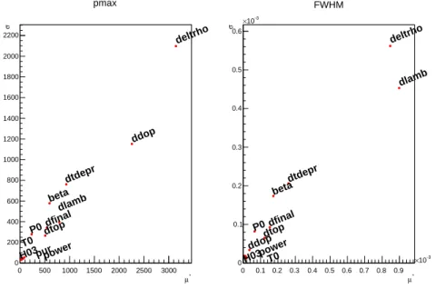
The first step of this sensitivity analysis is to sort the uncertain parameters with the Morris screen-ing method. 116 simulations were launched for a total of 1 hour of computscreen-ing time. The figure 5
represents 2 (µ∗, σ) planes corresponding to the maximal power and the FWHM outputs. We
can assume from the Morris screening method that the uncertainties on the3He purity, the initial
temperature, the initial power and the aperture of the high flowrate channel control valve have negligible impacts on the total uncertainties. The other factors have non linear effects and/or
in-teractions more particularly the uncertainty on the3He reactivity. The uncertainty on the Doppler
coefficient has a big influence on the maximum power uncertainty. The uncertainty on the prompt neutron generation time has a big influence on the FWHM uncertainty.
2018-01-25 10:30:04 * µ 0 500 1000 1500 2000 2500 3000 σ 0 200 400 600 800 1000 1200 1400 1600 1800 2000 2200 P0 pur H03 T0 power beta dlamb deltrho ddop dfinal dtop dtdepr pmax * µ 0 0.1 0.2 0.3 0.4 0.5 0.6 0.7 0.8 0.9 3 − 10 × σ 0 0.1 0.2 0.3 0.4 0.5 0.6 3 − 10 × P0 H03 T0power beta dlamb deltrho ddop dfinal dtop dtdepr FWHM
The second step consists in computing the Sobol indexes. From the Morris screening method, the 4 uncertainties parameters with negligible impacts are eliminated in order to improve the perfor-mances of the Sobol indexes method. 8 uncertainties parameters are studied, 3000 simulations were launched to estimate the Sobol indexes. The Sobol indexes are represented as histograms on
figure 6 for the maximum power Pmaxand the FWHM.
2018-01-25 10:21:46
deltrho0 ddop dtdepr beta P0 dlamb dfinal dtop 0.1 0.2 0.3 0.4 0.5 0.6 0.7 0.8 0.9 1 First Total pmax
deltrho dlamb dtdepr beta dfinal dtop P0 ddop 0 0.1 0.2 0.3 0.4 0.5 0.6 0.7 0.8 0.9 1 First Total FWHM
Figure 6: Sobol indexes associated to the maximum power and on the FWHM
Let’s rank the uncertainties parameters according to figure 6:
1. ∆ρ3He (deltrho): S∆ρ
3He(Pmax) = 71%, ST ∆ρ3He(Pmax) = 59%, S∆ρ3He(F W HM ) =
50%, ST ∆ρ3He(F W HM ) = 47%;
2. ∆Λ (dlamb): S∆Λ(F W HM ) = 36%, ST ∆Λ(F W HM ) = 40%;
3. ∆Dop (ddop): S∆Dop(Pmax) = 23%, ST ∆Dop(Pmax) = 21%;
4. ∆tc(dtdepr): S∆tc(Pmax) = 5%, ST ∆tc(Pmax) = 7%, S∆tc(F W HM ) = 7%, ST ∆tc(F W HM ) =
6%;
5. βef f (beta): Sβef f (Pmax) = 1%, ST βef f(Pmax) = 5%, Sβef f (F W HM ) = 3%, ST βef f (F W HM ) =
4%;
The other parameters have negligible effects. The uncertainties on models represent most of the total uncertainties on the transients characteristics for “natural” transients.
4.3. Sensitivity analysis for the “structured” transient
The same approach is applicable to the “structured” transients. Here is one example trying to
reproduce a 30 ms FWHM transient. The figure 7 represents 2 (µ∗, σ) planes corresponding to the
maximal power and the FWHM outputs. The Morris process took 80 minutes of computing time to simulate 134 transients. We can assume from the Morris screening method that the uncertainty on
the aperture of the high flowrate channel control valve and on the stabilized power are negligible. The other factors have non linear effects and/or interactions, more particularly the uncertainty on the opening instant of the second fast valve.
2018-01-25 10:40:33 * µ 0 200 400 600 800 1000 σ 0 100 200 300 400 500 600 700 P0 pur H03 H04 T0 power topen beta dlamb deltrho dfinal ddop dtop dtdepr pmax * µ 0 0.0005 0.001 0.0015 0.002 0.0025 0.003 0.0035 0.004 0.0045 σ 0 0.0005 0.001 0.0015 0.002 0.0025 0.003 P0 pur H03 H04 T0 power topen beta dlamb deltrho dfinal ddop dtop dtdepr FWHM
Figure 7: Input sensitivity ranking with Morris method for the “structured” transient
From the Morris screening method, the 2 uncertainties parameters with negligible impacts are eliminated in order to improve the performances of the Sobol indexes method. 12 uncertainties parameters are studied, 4200 simulations were launched to estimate the Sobol indexes. The Sobol
indexes are represented as histograms on figure 8 for the maximum power Pmaxand the FWHM.
2018-01-30 09:24:44
topendeltrho dtopddopdtdepr P0 pur H04 T0 betadlambdfinal 0 0.1 0.2 0.3 0.4 0.5 0.6 0.7 0.8 0.9 1 First Total Pmax
topen dtopdtdeprdeltrhopur H04 beta P0ddopdlambdfinal T0 0 0.1 0.2 0.3 0.4 0.5 0.6 0.7 0.8 0.9 1 First Total FWHM
Figure 8: Sobol indexes associated to the maximum power and the FWHM of the transient
1. ∆topen (topen): S∆topen(Pmax) = 40%, ST ∆topen(Pmax) = 36%, S∆topen(F W HM ) = 72%,
ST ∆topen(F W HM ) = 65%;
2. ∆T OP (dtop): S∆top(Pmax) = 18%, ST ∆T OP(Pmax) = 17%,S∆T OP(F W HM ) = 20%,
ST ∆T OP (F W HM ) = 18%;
3. ∆ρ3He (deltrho): S∆ρ
3He(Pmax) = 20%, ST ∆ρ3He(Pmax) = 17%, S∆ρ3He(F W HM ) = 2%,
ST ∆ρ3He(F W HM ) = 3%;
4. ∆Dop (ddop): S∆Dop(Pmax) = 16%, ST ∆Dop(Pmax) = 17%;
5. ∆tc(dtdepr): S∆tc(Pmax) = 6%, ST ∆tc(Pmax) = 9%, S∆tc(F W HM ) = 3%, ST ∆tc(F W HM ) =
3%;
Contrary to the “natural” transient case, the uncertainties on “structured” transients prediction is mainly due to an experimental parameter (topen). It impacts the test reproducibility. The uncer-tainty on FWHM for “structured” transients is also observed in real reactor conditions [3]. The TOP effect uncertainty has also a big influence on the “stuctured” transient uncertainty contrary to the “natural” transient case.
The sensitivity analysis shows that different parameters can have an impact on the power
tran-sient shape. We should continue efforts for knowledge on poison reactivities (3He, control rods)
especially the interactions between them. The Doppler feedback uncertainties can be improved by analyzing nuclear data impact on Doppler coefficient and materials thermal properties impact on fuel temperature during the transients. We can reduce the uncertainties on the depressuriza-tion models and on the TOP effect model by measuring a lot of “natural” transients in different
configurations. It includes a more precise estimation of the kinetic parameters (βef f,Λef f) and
their uncertainties. We should also improve the precision of the fast opening valves timing for the “structured” transients in order to reduce the uncertainty on FWHM.
5. CONCLUSIONS
The newly developed SPARTE code, based on physics, Best Estimates simulations and experi-mental analysis allows the prediction of the CABRI power transients calculation. In this paper we broached the subject of uncertainties associated to the prediction of the power transients by calculations. Uncertain simulation parameters and models were chosen and their uncertainties estimated in order to propagate through the SPARTE code. We dealt with 2 examples, correspond-ing to the CABRI typical power transients (“natural” and “structured” transients). The sensitivity study shows that the uncertainties on prediction are mostly due to model uncertainties in the case of a “natural” transient. Those uncertainties don’t affect the reproducibility of those power tran-sients. The sensitivity study confirms measurements showing that the uncertainty on “structured” transients is mostly due to one parameter: the second fast valve opening time. We can conclude that the SPARTE code associated to the propagation method is ready to predict the CABRI power transients and estimate the uncertainties of this prediction. Those overall uncertainties could be reduced by the reduction of inputs and models uncertainties. The present approach opens the way to optimization study of the CABRI power transients characteristics.
REFERENCES
[1] B. Duc, B. Biard, P. Debias, L. Pantera, J.-P. Hudelot, and F. Rodiac. “Renovation, improve-ment and experiimprove-mental validation of the Helium-3 transient rods system for the reactivity injection in the CABRI reactor.” In International Group On Research Reactors (2014). Bar-iloche, Argentina, November 17 - 21.
[2] O. Clamens, J. Lecerf, J.-P. Hudelot, B. Duc, T. Cadiou, P. Blaise, and B. Biard. “As-sessment of the 3He pressure inside the CABRI transient rods - Development of a
sur-rogate model based on measurements and complementary CFD calculations.” EPJ Web
of Conferences, volume 170, p. 04005 (2018). URL https:/articles/epjconf/abs/2018/05/
epjconf animma2018 04005/epjconf animma2018 04005.html.
[3] O. Clamens, J. Couybes, J. Lecerf, J.-P. Hudelot, B. Duc, L. Pantera, P. Blaise, and B. Biard. “Analysis of the CABRI power transients - Prediction improvements using a combination of measurements and calculation.” In Proc. Int. Conf. ANIMMA2017. Liege (2017).
[4] F. Gaudier. “URANIE: The CEA/DEN Uncertainty and Sensitivity platform.” Procedia - Social and Behavioral Sciences, volume 2(6), pp. 7660–7661 (2010). URL http://www. sciencedirect.com/science/article/pii/S1877042810013078.
[5] Guillaume Ritter, Remi Berre, and Laurent Pantera. “DULCINEE. Beyond neutron kinetics, a powerful analysis software.” In RRFM IGORR (2012). Prague, Czech Republic, March 18 - 22.
[6] “ROOT: ROOT Reference Documentation.” URL https://root.cern.ch/doc/master/index.html. [7] J. Lecerf, Y. Garnier, J. Hudelot, B. Duc, and L. Pantera. “Study of the linearity of CABRI experimental ionization chambers during RIA transients.” EPJ Web of Conferences, volume 170, p. 04015 (2018). URL https:/articles/epjconf/abs/2018/05/epjconf animma2018 04015/ epjconf animma2018 04015.html.
[8] G. Truchet, P. Leconte, A. Santamarina, E. Brun, F. Damian, and A. Zoia. “Computing adjoint-weighted kinetics parameters in Tripoli-4 by the Iterated Fission Probability method.” Annals of Nuclear Energy, volume 85, pp. 17–26 (2015). URL http://www.sciencedirect. com/science/article/pii/S030645491500225X.
[9] E. Brun, E. Dumonteil, F. Hugot, N. Huot, C. Jouanne, Y. Lee, F. Malvagi, A. Mazzolo, O. Petit, J. Trama, and others. “Overview of TRIPOLI-4 version 7, Continuous-energy Monte Carlo Transport Code.” (2011).
[10] A. Santamarina, D. Bernard, P. Blaise, M. Coste, A. Courcelle, T. Huynh, C. Jouanne, P. Leconte, O. Litaize, S. Mengelle, and others. “The JEFF-3.1. 1 nuclear data library.” JEFF report, volume 22(10.2), p. 2 (2009).
[11] P. Leconte, G. Truchet, J.-F. Vidal, A. Santamarina, and P. Blaise. “Validation of the
APOLLO2.8 code package for the calculation of βeff and Λ kinetics parameters and the reactivity versus reactor period relationship.” In PHYSOR2016. Sun Valley, USA (2016).
[12] M. D. Morris and T. J. Mitchell. “Exploratory designs for computational experiments.”
Journal of Statistical Planning and Inference, volume 43(3), pp. 381–402 (1995). URL http://www.sciencedirect.com/science/article/pii/037837589400035T.
[13] A. Saltelli. “Making best use of model evaluations to compute sensitivity indices.”
Com-puter Physics Communications, volume 145(2), pp. 280–297 (2002). URL http://www.