– PIANC Workshop –
In the framework of the
PIANC Report n°106 ‐ INCOM WG29
‐ ABSTRACTS ‐
13
th
– 14
th
September 2011
New Orleans – USA
PIANC – www.pianc.org
Editor: Prof. Ph. RIGO, INCOM WG29 Chairman
What’s new in the design
of navigation locks?
International Workshop on “Navigation Locks”, PIANC – New Orleans, USA, 13‐14th Sept 2011 i
This 2nd international workshop presenting the Innovations in Navigation Lock
Design - PIANC Report n°106 was organized on 13th and 14th September2011 in
New Orleans, USA. The first workshop in September 2009 in Brussels, Belgium was a huge success, with more than 100 participants, and therefore, it was decided to offer follow up events.
This 2nd international PIANC workshop on Innovations in Navigation Lock
Design will be held in conjunction with the SMART-RIVERS 2011 Conference
in New Orleans, Louisana.
On 13th Sept 2011, there was a detailed presentation of the main innovative
issues highlighted in the PIANC 2009 report (n°106). This workshop differs from the 2009 one in that new speakers presented their experience with respect to innovative lock design, including the new Panama Locks.
On 14th Sept. 2011, the workshop was dedicated to “Ship behavior in locks and
lock approaches”.
For info about SMART RIVERS 2011: http://smart11.pianc.us
Workshop proceeding
The Workshop proceeding (including all the PowerPoint presentations given during the workshop – in PDF
version) is release on the PIANC web site (www.pianc.org ) and on
www.anast.ulg.ac.be ,
www.anast.ulg.ac.be/index.php/fr/nouveautes/40-categorynews/102-pianc-whats-new-in-the-design-of-navigation-locks
Proceedings of the 1st PIANC workshop (Brussels 2009) are available at:
www-new.anast.ulg.ac.be/index.php/en/news/40-categorynews/94-pianc-workshop-innovations-in-navigation-lock-designq
and
www.pianc-aipcn.be/figuren/verslagen%20activiteiten%20Pianc%20België/fotoboekjes/workgroup/
locks/Locks/index.html
International Workshop on “Navigation Locks”, PIANC – New Orleans, USA, 13‐14th Sept 2011 ii
The participants of the PIANC 2011 workshop are:
Pablo Arecco [email protected]
Nicolas Badano [email protected]
Pierre Bayart [email protected]
Joerg Boedefeld [email protected]
Cathy Boone [email protected]
Didier Bousmar [email protected]
Ryszard A. Daniel [email protected]
Michael De Beukelaer-Dossche [email protected]
Wim De Cock [email protected]
Tom De Mulder [email protected]
Z.David DeLoach [email protected]
Jean-Pierre Dubbelman [email protected]
Claude Dumont [email protected]
Karim El Kheiashy [email protected]
Jose Luis Fernandez [email protected]
Sergio Gaitan [email protected]
Marie Gaudreault [email protected]
Rogelio Gordon [email protected]
Diana Hallman [email protected]
Allen Hammack [email protected]
Andy Harkness [email protected]
Dale Heller [email protected]
Olli Holm [email protected]
Gangarao Hota [email protected]
Peter Hunter [email protected]
Anne-Caroline Kiekens [email protected]
Stephen Kwok [email protected]
Charles Laborde [email protected]
Ryan Laughery [email protected]
Jun Li [email protected]
Ellen Maes [email protected]
William Miles [email protected]
Dale Miller [email protected]
Alvaro Moreno [email protected]
Karl Morgen [email protected]
Michael Newbery [email protected]
Erwin Pechtold [email protected]
Wu Peng [email protected]
Philippe Rigo [email protected]
Sebastien Roux [email protected]
Marc Sas [email protected]
Laid Temacini [email protected]
Rik Thomas [email protected]
Carsten Thorenz [email protected]
Louis Van Schel [email protected]
Marc Vantorre [email protected]
Hans Veldman [email protected]
Craig Waugaman [email protected]
Otto Weiler [email protected]
International Workshop on “Navigation Locks”, PIANC – New Orleans, USA, 13‐14th Sept 2011 iii WORKSHOP - TECHNICAL AGENDA
13th Sep 2011 (Tuesday)
8:00 WORKSHOP INTRODUCTION
By Prof. Ph. RIGO (BE), INCOM Vice chairman
and J. CLARKSON (U.S. Army Corps of Engineers, member of INCOM WG29) 8:30-10:00 WORKSHOP PART 1 – THE PANAMA LOCKS
THE DESIGN OF THE PANAMA LOCKS
By M. NEWBERY (USA) and J. AUGUSTIJN (NL) Chair: Ph. RIGO (BE)
NUMERICAL SIMULATIONS AND EXPERIMENTAL MODELS: THE EXPERIENCE OF THE NEW PANAMA MODEL
By S. ROUX (Fr)
Discusser: R. STOCKSTILL (USA)
10:30-12:00 WORKSHOP PART 2 – PIANC 2009 - Report n°106 - on Locks INNOVATIONS IN NAVIGATION LOCK DESIGN
General Presentation of the PIANC Report n°106 on Locks (2009)
By Ph. RIGO (BE) and P. HUNTER (UK),
A SELF-CONTAINED HIGH-LIFT LOCK WITH WATER-SAVING BASINS
By C. THORENZ (D)
INNOVATION IN LOCK FILLING AND EMPTYING SYSTEMS ByR. STOCKSTILL (USA)
Discusser:D. BOUSMAR (BE)
CONSTRUCTION METHODS
By D. MILLER (USA) Discusser: WU. PENG (China)
13:30 – 15:00 WORKSHOP PART 3 – PIANC 2009 - Report n°106 – on Locks (cont.) COMPUTER FLUID DYNAMICS IN LOCK DESIGN
By T. DE MULDER- (BE) Discusser: C. THORENZ (D)
NEW CONCEPT OF LOCK GATES
- Use of synthetic materials and the comeback of sliding gates versus rolling gates By R. DANIEL (NL) and J. AUGUSTIJN (NL)
- New materials and systems in the design of miter gates
By R. DANIEL (NL)
- Innovation in lock equipment
By O. HOLM (Fin) and J. BODEFELD (D) 15:30 – 17:00 WORKSHOP PART 4 – CHALLENGES OF TOMORROW
DESIGN FOR MAINTENANCE: DREAM OR REALITY? THE EXPERIENCE OF THE NEW PANAMA LOCKS – LIST OF REQUIREMENTS(20 min + 10 min questions)
By R GORDON and J. WONG (ACP) Chair: J. BODEFELD (D) and P. HUNTER (UK)
IDENTIFICATION OF THE CHALLENGES OF TOMORROW
PANEL MEETING
Coordinator: Ph. RIGO
Panelists: J. AUGUSTIJN (NL), J. BODEFELD (D), R. DANIEL (NL), R GORDON & J.WONG (ACP), M. NEWBERY (USA), R. THOMAS (BE)
17:00 – 17:30 PROJECT REVIEWS and their value in realising innovations,By E. PECHTOLD (NL) 17:30 CLOSURE By Ph. RIGO (BE)
14th September 2011 (Wednesday Afternoon)
8:30 – 12:00 SMART-RIVERS Conference
Keynote addresses and Plenary Session on Hurricane Surge Barrier
12:00 – 13:30 Lunch – with keynote speaker from EU commission (invited)
13:30 – 15:30 WORKSHOP PART 5 : MOORING FORCES AND VESSEL BEHAVIOUR (in locks)
EXPERT PANEL SESSION – Ph RIGO (BE)
The experts present their experience on this issue, which is the main focus of the new PIANC WG 155 (having their inaugural meeting during the SMART RIVERs Conf.)
Presentation of new innovative concepts for navigation locks By S. KWOK (St. Lawrence Seaway, Canada)
Experience in Belgium
By T. DE MULDER, M. VANTORRE (BE) Experience in China By WU PENG (China) Experience in France By S. ROUX (Fr) Experience in Germany By C. THORENZ (D) Experience in The Netherlands
By J.J. VELDMAN (NL) Experience in USA
By R. STOCKSTILL (USA)
Discussion : Coordinated by Ph RIGO (BE) 15:30 – 16:00 Break
16:00 – 17:00 WORKSHOP PART 6 : VESSEL BEHAVIOUR (in locks)
Chair: WU PENG (China)
INTERACTION between SALT WATER INTRUSION and NAVIGATION (in locks)
By M. SAS (BE)
MANEUVRABILITY IN LOCK CHANNELS
By M. VANTORRE (BE)
17:00 -17:30 WORKSHOPCLOSURE By PIANC USA Representative
PIANC HQ Representative
TABLE OF CONTENT
INTRODUCTION
Ph. RIGO, PIANC INCOM Vice Chairman (BE)
THE PANAMA LOCKS (Part 1)
Paper 1-1 THE DESIGN OF THE PANAMA LOCKS
M. NEWBERY (USA) and J. AUGUSTIJN (NL)
Paper 1-2 NUMERICAL SIMULATIONS AND EXPERIMENTAL MODELS: THE
EXPERIENCE OF THE NEW PANAMA MODEL
S. ROUX (Fr)
PIANC REPORT n°106 on LOCKS (2009) (Parts 2 and 3)
Paper 2-1 INNOVATIONS IN NAVIGATION LOCK DESIGN
General Presentation of the PIANC Report n°106 on Locks (2009)
Ph. RIGO (BE) and P. HUNTER (UK),
Paper 2-2 A SELF-CONTAINED HIGH-LIFT LOCK WITH WATER-SAVING BASINS
C. THORENZ (D)
Paper 2-3 INNOVATION IN LOCK FILLING AND EMPTYING SYSTEMS
R. STOCKSTILL (USA)
Paper 2-4 CONSTRUCTION METHODS
D. MILLER (USA)
Paper 3-1 COMPUTER FLUID DYNAMICS IN LOCK DESIGN
T. DE MULDER- (BE)
NEW CONCEPTS OF LOCK GATES (Cont. part 3)
Paper 3-2 Use of synthetic materials and the comeback of sliding gates versus rolling gates
R. DANIEL (NL) and J. AUGUSTIJN (NL)
Paper 3-3 New materials and systems in the design of miter gates
R. DANIEL (NL)
Paper 3-4 Innovation in lock equipment
O. HOLM (Fin) and J. BODEFELD (D)
Paper 3-5 PROJECT REVIEWS and their value in realising innovations
E. PECHTOLD (NL)
What’s new in the design
of navigation locks?
CHALLENGES OF TOMORROW (Part 4)
Paper 4-1 DESIGN FOR MAINTENANCE: DREAM OR REALITY? THE EXPERIENCE OF THE NEW PANAMA LOCKSLIST OF REQUIREMENTS
R. GORDON and J. WONG (ACP)
Paper 4-2 IDENTIFICATION OF THE CHALLENGES OF TOMORROW -
PANEL MEETING
Coordinator: Ph. RIGO
Experts: J. AUGUSTIJN (NL), J. BODEFELD (D), R. DANIEL (NL), R. GORDON (ACP), M. NEWBERY (USA),
R. THOMAS (BE), J.WONG (ACP).
MOORING FORCES AND VESSEL BEHAVIOUR IN LOCKS (Parts 5 and 6)
Paper 5-1 Experience in Belgium
T. DE MULDER (BE), M. VANTORRE (BE)
Paper 5-2 Experience in China
WU PENG (China)
Paper 5-3 Experience in France
S. ROUX (Fr)
Paper 5-4 Experience in Germany
C. THORENZ (D)
Paper 5-5 Experience in The Netherlands
J.J. VELDMAN (NL)
Paper 5-6 Experience in USA
R. STOCKSTILL (USA)
Paper 5-7 Presentation of new innovative concepts for navigation locks
S. KWOK (Canada)
Paper 6-1 INTERACTION between SALT WATER INTRUSION and NAVIGATION (in
locks)
M. SAS (BE)
Paper 6-2 MANEUVRABILITY IN LOCK CHANNELS
PAPER 1-1 “What’s new in the design of navigation locks” 2nd International Workshop, PIANC – New-Orleans, 13-14 Sept. 2011
PIANC – New Orleans The Post Panamax Locks Page 1/4
The Post-Panamax Locks
The Design of the Panama Canal Third Set of Locks
M. Newbery
Design Manager - CICP, and Vice President - MWH
J. Augustijn
Rotterdam Design Center Engineer- CICP, and Project Manager – Iv-Infra
ABSTRACT: This paper provides a high level summary of some key design elements of the Atlantic and Pacific Third Set of Locks. It describes the evolution of the design from the tender design to final designs. Particular emphasis is placed on the design challenges posed by the technical requirements for the lock rolling gates together with CICP’s solutions as presented in the accepted final designs.
1 INTRODUCTION AND TENDER DESIGN The Panama Canal Third Set of Locks is being constructed for the Panama Canal Authority under a design-build contract. The contract was awarded in August 2009 to Grupo Unidos por el Canal (GUPC), a JV consortium of Sacyr (Spain), Impregilo (Italy), Jan de Nul (Belgium) and CUSA (Panama). The project is scheduled to be completed in October 2014. The award was made on a best value basis (combination of qualifications and price); GUPC was rated highest of the three bids in both catagories. The tender design was prepared by CICP Consultores Internacionales (CICP), a design JV led by MWH (USA), along with member firms Tetra Tech (USA) and Iv-Infra (Holland).
The design team (several of whom have worked on the expansion project for ACP since 1999) evolved the ACP’s concept design through innovations in the hydraulic design, the concrete structures, and the lock gates. Hydraulics were simplified for the intakes, outlets, and water saving basin conduits. Structures were optimized through detailed soil-structure modeling and FEM analysis. Lock gate operating speed was increased for additional capacity. These improvements resulted in the highest technical ranking and were key to reducing the construction cost.
2 FINAL DESIGN
Final design by CICP has been on-going since 2009. The designs are being prepared at design centers in Chicago, Bellevue, Buenos Aires, Rotterdam and Milan and cooridinated though CICP’s Design Integration Office (DIO) co-located with GUPC’s staff in Panama. Design staffing levels are peaking in 2011 (with both design and construction on-going) at around 250 full-time equivalent engineers and support. Design centers are linked for collaboration by a dedicated server system on which all designs, documents and drawings are stored. Work products are delivered to GUPC via the Aconex document management system. Multiple design tools are employed for the production of around 10,000 permanent works drawings. These include Revit, AutoCad, Civil 3-D, Microstation and Tekla. Navisworks is used to integrate the various models and perform clash detection in real-time.
Fig. 1. Revit Model, Atlantic Lock Complex
PAPER 1-1 “What’s new in the design of navigation locks”
2nd International Workshop, PIANC – New-Orleans, 13-14 Sept. 2011
PIANC – New Orleans The Post Panamax Locks Page 2/4
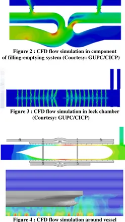
Hydraulic design comprised developing a complete 3-D numerical model using OpenFoam, performing additional optimizations, and extensive physical model testing (by CNR in Lyon, France, at 1:30 scale). The modeling resulted in adjustments to the conduit/secondary culvert connection, the water saving bason intakes/outlets, and the culvert valve elevations. All filling and emptying requirements were met or exceeded, including criteria for maximum ship hawser forces for two design vessel types.
Fig. 2. Hydraulic Model of Post Panamax Locks
Geotechnical studies comprised development of 3-D topography and excavation models in Microstation, stability analyses, foundation characterization, seepage and drainage analysis and design and development of seismic loading for both the Atlantic and Pacific lock complexes. To better characterize seimic loads, deconvolution was used to modify seven seismic outcrop time-histories for use as input to the structural modeling.
Structural design of the nearly 5 106 m3 of concrete
comprises extensive 2-D and 3-D modeling of the lock chamber monoliths and lock heads using Abaqus software. Non-linear finite element analysis (FEA) models were developed for the analysis including a 3-D combined lock head and lock gates model, believed to be a first. Analysis included a combination of static and seismic loads. Results for the seven seismic time histories were averaged to obtain analysis results. Run times on super computers for the non-linear seismic analysis exceeded 48 hours per time history for the larger lock head FEA models.
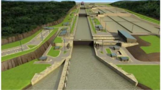
Fig. 3. Image of Pacific Lock Middle and Lower Chambers superimposed on aerial photograph. Fender systems are still under development at the time of writing, but are likely to include multiple horizontal fenders in the lock chamber to faciliate sliding during ship movement from chamber to chamber. Unique articulated multiple wheel fenders are proposed for the corner fenders. Approach wall fenders are proposed as hybrid cone panel units. Control of the lock filling and emptying system is a key design challenge, accomplished through sixty-four 6.5m x 4.5 m culvert valves, 72 6.5m x 4.2m conduit valves along with 16 4.0 m x 3.0m equilization valves, providing complete redundancy. Valve opening and closing times can range from 1 minute to 6 minutes, with actuation of hydraulic cylinders by means of continously variable hydraulic power units (HPU’s). Each complex has a total of 42 operations buildings which are now under final design. The mechanical, electrical and controls systems also provide complete redundancy to provide the high degree of reliability and availability required by the technical specifications. Because only a single lane of Post-Panamax locks is provided, a high availability of 99.6% is mandated. 3 LOCK ROLLING GATE DESIGN
Each three-lock chamber complex includes four lock heads housing the rolling gates. Redundant gates in each lock head makes for a required 16 gates in total for the two lock complexes. The gates are 60 m wide, up to 10 m thick and 30 m high. The average weight is around 3,000 Tonnes. With an
PAPER 1-1 “What’s new in the design of navigation locks” 2nd International Workshop, PIANC – New-Orleans, 13-14 Sept. 2011
PIANC – New Orleans The Post Panamax Locks Page 3/4
average lift of around 9 m between lock chambers, the lock gates must hold as much as 20 m of differential head.
However, it is not just the sheer size that makes the design of these gates unique. The project’s location in a highly seismic area requires that the lock gates be designed using the current state of practice, whereby both seismic design spectra and the suite of seven time histories are used in the analysis. The time history analyses were carried out using super computers in a complex multi-component model containing the lock head, its backfill and the two rolling gates. The model not only includes non-linear interfaces between lock head and the gates, it also incorporates the complex hydrodynamic loadings of the water. Following extensive research the water is modeled in the form of lumped added masses calculated with the Westergaard formula.
The added water mass under seismic loading is around ten times the weight of the gate. To confirm the applicability of the Westergaard formulation, CICP performed extensive analyses. These included computer simulations, several full scale tests shaking existing gates at their own frequency, and a laboratory scale model test. Through these state-of-practice analyses, it was concluded that the Westergaard formula is applicable.
To service the expected high demand for Canal transits, the envisaged use of the Third Set of Locks is significantly higher than that of typical locks - on the order of 15 to 20 operations per day over their 50 year design life. This high level of usage means that the amount of lock gate load cycles are such that fatigue loading is in many cases a governing normal load case. In addition to these ‘normal’ load cases, special load cases such as dry outages and ship impact have been investigated and considered in the design.
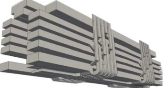
Fig. 4. Longitudinal section of a lock rolling gate showing buoyancy chambers, trusses and the upper support bracket. Tekla 3-D model.
Structurally, the lock gates are similar to a ship or submarine hull in design. As such, they are equipped with a buoyancy chamber, a submerged steel box filled mostly with air, which reduces the operational weight of the gate to about 7% of its actual weight. A key requirement for the gates is that they are able to be floated out for repair or relocation. This is a conventional requirement for the design of this type of lock gates, but it is complicated by the need to design for low chamber water levels. As a result, the buoyancy chambers need to be located near the bottom of the gate making it impossible to float the gate in a stable manner. This problem was solved by the introduction of a flotation hull, which can be formed by inserting watertight panels at the top of the gate structure, thereby increasing buoyancy and, with addition of ballast at the bottom of the lock gate, providing stable flotation.
The lock gate drive system consists of a duplicate set of winches and wire ropes. The design of the reeving system is such that the force driving the gate always acts on the centreline. The winches are connected to gearboxes that are driven by electrical motors. Acceleration and deceleration of the motors are accomplished by a variable frequency drive. If one motor/gearbox or winch fails, the other set can take over, adding to the reliability of gate operations.
During movement the operational weight of the gate is carried by two wagons in a so-called “wheelbarrow” arrangement. The ‘upper’ wagon carries one end of the gate via a bracket, and rolls over a set of rails located in the top of the lock head.
PAPER 1-1 “What’s new in the design of navigation locks”
2nd International Workshop, PIANC – New-Orleans, 13-14 Sept. 2011
PIANC – New Orleans The Post Panamax Locks Page 4/4
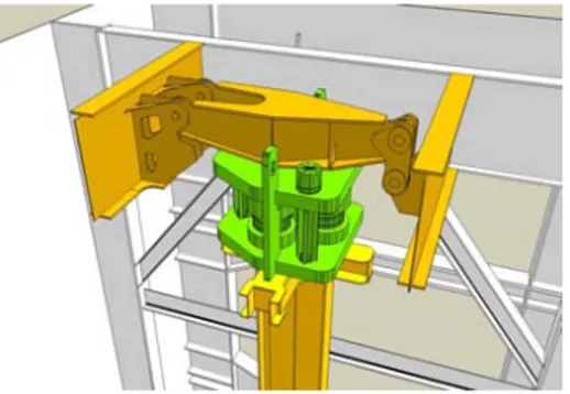
The upper wagon is connected to the drive system and pushes or pulls the gate during operation. The other end of the gate is supported by the lower wagon running on a rail track located in the lock head sill. The lower wagon is connected to a column which carries the gate’s operational weight near the top. The design of the wagon attachments - specifically the column for the lower wagon and the bracket to the upper wagon - makes it possible to replace either wagon within four hours. Extreme loads on the wagons, for example due to leakage after a ship collision or due to a major earthquake, are controlled by a load limiting device. This device consists of a set of pre-stressed springs that behave rigidly up to a threshold value, and then elastically when this value is exceeded. The elastic behavior of the springs at high loading enable the gate to settle to the lock head floor on vertical bearing blocks. This prevents the load on the wagons from exceeding the maximum allowable value.
Fig. 5. Load limiting device arrangement at the top of the lower wagon column. Tekla 3-D model.
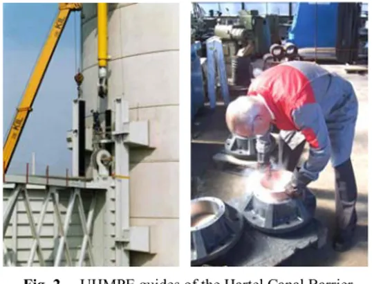
Horizontal water loads on the gate are transferred to the lock head by the guide and bearing system. When the lock gate is in the closed position and retaining water, load transfer to the lock head structure is accomplished by a set of lateral bearing blocks along the vertical edges and along the bottom of the downstream side of the lock gate. During movement, the remaining horizontal forces (e.g., those due to residual differential head, salinity differences, wind and wave loads) are transferred to the lock head by guide blocks located near the corners of the lock gate.
For the guide and bearing blocks, ultra high molecular weight polyethylene (UHMW-PE) has
been selected for its strength and low-friction properties. Because of their good combined sliding properties, the combination of UHMW-PE and stainless steel has been chosen for the guide system. The UHMW-PE guide blocks are attached to the gates, while the bearing plates are stainless steel embedded in the lock head sill. Apart from carrying loads, the bearing plates also serve as a sealing surface. Due to stringent requirements with regard to leakage, the bearing and sealing surfaces are separated, withseparate rubber seals applied.
The lock gates are designed to be maintained within their recesses, with a recess closure and dewatering system provided for this purpose. For maintenance, the gate can be floated up in the recess and suspended on maintenance supports. Maintenance can then take place in the recess, without interruption of the operation of the lock, a key requirement to meet the availability criteria. 4 NEXT STEPS
Construction is underway with excavation and foundation preparation advanced at both sites. Structural concrete placement should also be advancing at both sites by September 2011. Lock gate fabrication by Cimolai (Italy) has commenced as has valve fabrication by Hyundai (South Korea). Design is focused on completing the water saving basins, approach walls and wing walls together with the project control system, buildings and electro-mechanical systems. In addition, design now includes review of shop drawings, reinforcement and embedment drawings, as well as a quality assurance role in reviewing construction and major equipment suppliers.
An evolving construction plan for both sites has led to changing design priorities with associated coordination challenges – to be expected on a design-build project. Standing up a quality management system across 3 companies, 3 continents, 5+1 design centers has been critical to the technical success of the project. Having highly qualified key technical staff has been, is and will be essential to the succesful outcome of the project design.
PAPER 1-2 “What’s new in the design of navigation locks” 2nd International Workshop, PIANC – New-Orleans, 13-14 Sept. 2011
PIANC – New Orleans The Panama Locks - Page 1/4
The Panama Locks – Numerical simulations & experimental models:
the experience of the new Panama model
S. Roux
Laboratoire de Mesures et d’Essais, Compagnie National du Rhône, France
N. Badano
MWH, Argentina
ABSTRACT: The combined used of physical and numerical model gives birth to a very powerful “hybrid” model that helps the designer to minimize the calculation time, cross-check the results, access to a large number of data and improve the prediction of the hydraulic performance of the prototype. In the case of the final design study of the Post-Panamax locks, the combined use of a physical model, 1D, 2D & 3D numerical models have proven to be a very efficient tool through a lot of cases which are presented in this paper for some of them.
1 INTRODUCTION
In the frame of the construction works of the New Locks of the Panama Canal, the final design of the locks F-E system has been carried out using both a physical scale model and a set of 1D, 2D and 3D numerical models. The physical model has been run in the Laboratory of the Compagnie Nationale du Rhône in Lyon while the numerical model studies were performed by MWH in Buenos Aires. Initially, numerical models had been run to fix the design to be tested in the physical model. Then, each model were run at the same time, allowing to cross-check the results and minimize the time to achieve the validation of the hydraulic performance of the F-E system.
2 DESCRIPTION OF THE PHYSICAL MODEL
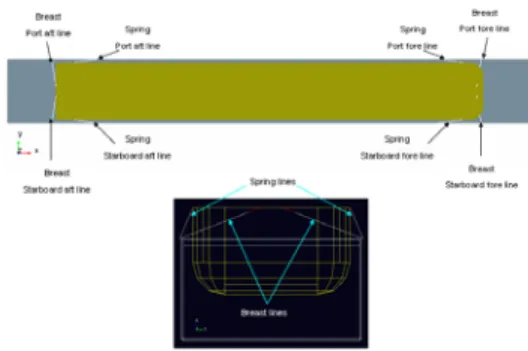
A scale model, 60 m long and 10 m wide, representing two lock chambers, three WSB associated to the lower chamber, one fore bay and one tail bay has been built at scale 1/30 in CNR laboratory.
This model has been equipped with about 100 sensors in order to measure:
- The water levels in the lock chambers, basins, fore and tail bays;
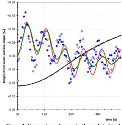
- The longitudinal and transversal differential water levels in the lock chamber (i.e. the longitudinal and transversal water slopes);
- The velocities and flow rate in the main culverts and WSB conduits;
- The pressure in the culverts and downstream the valves;
- The valve positions;
- The longitudinal and transversal hawser forces (i.e. the longitudinal and transversal components of the hydrodynamic force exerted by the water on the ship’s hull).
Figure 1: General view of the physical model A set of three Post-Panamax ship models at scale 1:30 were used for carrying out the tests in the physical model aimed at measuring the total forces exerted on the ship’s hull and calculate the hawser forces and vessel displacements.
PAPER 1-2 “What’s new in the design of navigation locks”
2nd International Workshop, PIANC – New-Orleans, 13-14 Sept. 2011
PIANC – New Orleans The Panama Locks - Page 2/4
3 PRESENTATION OF THE NUMERICAL MODEL USED DURING THE FINAL DESIGN STUDY
State-of-the-practice software was used to study the different problems:
- Local head losses at the different system components were computed using 3D models based on OpenFOAM, a formerly commercial code that has become freely available. Its main advantages over comparable commercial software are its high-performance (Linux-based, parallel processing), access to a worldwide forum to request support, and its flexibility to introduce new features, if needed. - The filling/emptying times and maximum flow velocities were calculated with a 1D model based on the commercial software FlowMaster V7.
- The hawser forces were inferred from the water surface slope values correlated during previous design phases. The water surface slopes were obtained using a 2D model based on Hidrobid software (a numerical code developed by Instituto Nacional del Agua) which is similar to other software like Mike 21 – by DHI –, or Delft2D.
All the models went through calibration or validation processes. The validation of OpenFOAM was based on comparisons with existing experimental results. The 1D model was first calibrated by comparison with experimental results from measurement carried out on the conceptual design physical model and with the results of the 3D models. Then, also the results of the physical model were used. The 2D model was validated by comparing its results with the results obtained with software Delft2D, and with measurements performed in the physical model.
4 EXAMPLES OF COMBINED USE OF PHYSICAL AND NUMERICAL MODELS
4.1 Calibration of the 1D model of the lock F-E system
The entire F-E system has been modeled with the Flowmaster 1D software, representing and setting the parameters of every component such as reservoirs, culvert, bends and valves. Anyway, some components such as the central flow connection present a very complicated hydraulic shape whose head losses coefficient can not been set without
additional calculations with 3D model and measurements carried out on the physical model.
Figure 2: central flow connection Once the 1D model has been calibrated, it becomes a very efficient tool allowing to perform fast sensitivity analysis, in order to define the operating parameters (i.e. valve opening schedule) before testing them on the physical model.
The construction of two 1D numerical models, one at scale 1/30 and the other at prototype dimensions, also gave very valuable information on the scale effects.
4.2 Assessment of the flow distribution through the lateral ports
Achieving a balanced flow distribution along the lateral ports is something of first importance in order to have smooth filling conditions. Before running all the F-E scenarios, a lot of measurements were carried out on the physical model in steady flow condition to assess the symmetry of the flow entering into the lock chamber.
These measurements have been completed by 3D numerical calculations that gave valuable data, such as distribution of the flow in every port, difficult to obtain by simple measurements on the physical model.
Figure 3: numerical calculation Vs observation on physical model
All this set of data allowed to get an accurate and comprehensive knowledge of the flow conditions in
PAPER 1-2 “What’s new in the design of navigation locks” 2nd International Workshop, PIANC – New-Orleans, 13-14 Sept. 2011
PIANC – New Orleans The Panama Locks - Page 3/4
every port and to validate the efficiency of F-E system regarding the flow distribution.
4.3 Upgrade of some components of the F-E system Tender design
The combined use of physical and numerical model has demonstrated its full efficiency through the modification of one main culvert valve layout.
Figure 4: Air entrainment under a valve After having detected visually on the physical model that some air was sucked in the main culvert downstream of one valve, a 3D numerical model of the valve has been implemented. It was validated on the basis of data measured on the physical model (especially pressure).
A new configuration of the valve layout has then been studied with the numerical model and the retained configuration has been installed on the physical model for validation.
This methodology has permitted in a very short time to ensure the results by cross-checking the data on both model and to optimize the F-E system modification from a financial point of view.
PAPER 2-1 “What’s new in the design of navigation locks” 2nd International Workshop, PIANC – New-Orleans, 13-14 Sept. 2011
PIANC – New Orleans PIANC Report n° 106 “Innovations in Navigation Lock Design” Page 1/2
PRESENTATION OF THE PIANC REPORT n°106 ON LOCKS
Ph. Rigo
Chairman of INCOM WG29, Prof. ULG-ANAST, Belgium
P. Hunter
Member of the INCOM WG29, HR Wallingford, UK
ABSTRACT: This introductory paper presents the PIANC report n° 106 (2009) on “Innovations in Navigation Lock Design”. Main objectives and issues are highlighted in this paper. This PIANC report has been achieved by the INCOM Working Group 29 of PIANC from 2006 to 2009.
1 INTRODUCTION
Locks are key structures for the development of navigation in canals and in natural rivers where weirs regulate water levels to enable navigation. They may also be strategic infrastructure for port development.
In lower elevation regions, such as New Orleans and the Netherlands, locks are structures in dikes and also have an important task in flood defence.
In 1986, PIANC produced a comprehensive report of 445 pages on Locks (PIANC, 1986). For about twenty years this report has been considered as a world reference guideline, but it now needed updating to include new design techniques and concepts. PIANC decided in 2006 to launch a new Working Group (WG) to update the report, and this present report is the result.. The new report must be considered more as a complement to the 1986 report than a replacement version, and focuses on new design techniques and concepts that were not reported in the former report. It covers all the aspects of the design of a lock but does not duplicate the material included in the former report. Innovations and changes that have occurred since 1986 are the main target of the present report.
The core of this report has three major parts. The first part (Section 3) presents an exhaustive list of design goals associated with locks. This section is particularly important for decision makers who have to launch a new project. The second part (Section 4) reviews the design principles that must be considered by designers. This section is methodology oriented. The third part (Section 5) is technically oriented. All main technical aspects
(hydraulics, structures, foundations, etc.) are reviewed, focussing on changes and innovations occurring since 1986. Perspectives and trends for the future are also listed. When appropriate, recommendations are listed.
Major changes since 1986 concern maintenance and operational aspects, and more specifically how to consider these criteria as goals for the conceptual and design stages of a lock. Renovation and rehabilitation of existing locks will be an increasingly important topic for the future.
In natural rivers, locks are usually associated with movable weirs, and in coastal areas with flood protection structures. In 2006 PIANC published the InCom-WG26 report “Design of Movable Weirs and Storm Surge Barriers” (PIANC 2006). That report can be considered as a companion report to the present report as locks and weirs have many design aspects in common. Some design aspects are not discussed in this report since they have already been developed in the InCom WG26 report on weirs (for instance: multi-criteria assessment for comparison of design alternatives, ...).
Section 2 of this report also includes more than 50 project reviews of existing (and planned) lock projects describing them and their innovative aspects. Some innovative and untested concepts are also mentioned as references although with no guarantee of validity.
2 AIMS OF THE INCOM-WG29 AND TERMS OF REFERENCE
The objectives of the InCom-WG29 were defined by the Terms of Reference (ToR) proposed by the
PAPER 2-1 “What’s new in the design of navigation locks”
2nd International Workshop, PIANC – New-Orleans, 13-14 Sept. 2011
PIANC – New Orleans PIANC Report n° 106 “Innovations in Navigation Lock Design” Page 2/2
Inland Navigation Commission (InCom) and approved by the PIANC Executive Committee (ExCom) in late 2005. The ToR required establishing a comprehensive review of modern technologies and research results used to design and build navigation locks. A clear commitment was that only concepts and technologies not discussed in the previous PIANC 1986 report were to be considered and reported in this new report.
So, topics investigated here include:
a) Design objectives and optimization goals for locks
b) Innovative lock design concepts c) Innovative technical solutions.
Recent lock projects of interest are listed, reviewed and analyzed.
Recommendations for studies needed at the
conceptual and design stages of a lock are established.
In addition, maintenance and operational
requirements are discussed and listed.
A detailed reference list is included in the new report. Documents were analysed and compared by the WG to give engineers, designers and authorities a reference list allowing them to access relevant information to solve their problems.
To assist continuity and to avoid duplication of existing PIANC material the former 1986 PIANC Report on Locks is included on the DVD attached to the report (Directory A3). In addition, its Table of Contents is printed in Annex I of the report. These should be used as support to this report and as a baseline of standard practice.
3 DVD of the PIANC REPORT n°106
Due to publishing constraints the number of pages of the PIANC n°106’s hardcopy report was limited. Therefore additional information has been saved on a companion DVD (attached to the PIANC hardcopy report) - see list here after. Care should always be taken to use the current versions of standards and other publications that might supersede the versions on the DVD.
4 FUTURE WORKS
Continuing developments in lock design will be assisted by further PIANC WGs on related topics.
The WG155 on behaviour of ships in locks, the WG151 on seismic effects and ship impact on lock
gates and the WG154 on design and operation of miter gates have started, and future other topics need to be prioritised.
The DVD of the PIANC Report 106 includes the following directories:
- A1: The Project Reviews of 56 lock projects. - A2: PIANC 2009 Lock Report (pdf)
- A3: PIANC 1986 Lock Report (pdf) – in French and English
- A4: PIANC Dictionary on Locks & Waterways - A5: LIST of LOCKS (Worldwide list)
- Additional information to various sections of this report (Directories B) such as:
o B4.6.1: Salt Water Intrusion
o B4.6.5: 3D Video Modelling of Construction Process
o B5.2: Hydraulic (Manoeuvring, Fendering, ...)
o B5.5: Gates and Valves o B5.7: Lock Equipment o B5.8.5: Lubricants and Bio Oils - Various technical guidelines (Directories C) :
o C1- Estoril'2006 - PIANC Congress Papers o C2- Beijing'2008 - AGA-2008 Papers. o C3- Navigation Lock - Ecluse de
Navigation (by N.M Dehousse, 1985) in French
o C4- Corps of Engineering, USA - Reports on Innovation
o C5- Chinese Codes
o C6- French Guidelines - Lubaqua (CETMEF)
o C7- Fish Passage In Lock o C8- Corrosion Protection
o C9- Planning of Lock Maintenance (example)
o C10- European Code For Inland Waterways (CEVNI)
o C11- Ship Impact
o C12- Seismic Impact of Lock Gates o C13- ISPS Code 2003 - IMO (Safety and
Security of Ship and Port) o C14- Panama Third Lock Lane o C15- Seine Nord Europe Canal (France) o C16- Three Gorges Locks, China
o C17- Specifications for Lock Design (Lanaye Lock, Belgium)
PAPER 2-2 “What’s new in the design of navigation locks” 2nd International Workshop, PIANC – New-Orleans, 13-14 Sept. 2011
PIANC – New Orleans A Self-Contained High-Lift Lockwith Water Saving Basins Page 1/3
A SELF-CONTAINED HIGH-LIFT LOCK WITH
WATER SAVING BASINS
C. Thorenz
Federal Waterways Research Institute (BAW), Germany
R. Rother, G. Schulz
Neubauamt Hannover, Germany
ABSTRACT: This paper presents the concepts for a high lift lock with integrated water saving basins, which is planned to be fully self-contained, i.e. doesn’t exchange water with the adjacent reaches.
1 INTRODUCTION
The Elbe Lateral Canal connects the port of Hamburg, located at the river Elbe, with the Mit-telland Canal, one of the most important canals in the network in Germany. The Elbe Lateral Canal has to overcome a height difference of 61 m. This is done in two steps, first with a double ship lift at Scharnebeck with 38 m lift height, than with a lock with 23 m lift height at Uelzen (both finished in 1976). The latter was originally a single lock with 185 m usable length (Uelzen I) which was later extended (finished in 2006) with a second lock of slightly larger dimensions (190 m x 12.5 m). Due to the increase in both traffic and typical ship length, the rather short caissons of the ship lift (100 m usable length) are no longer sufficient. Thus, investigations were started by the local planning authority (Neubauamt Hannover, NBA-H), whether an additional ship lift or instead a lock with water saving basins would be the most viable addition to the old ship lift.
2 HYDRAULIC CONCEPT
In the last two decades, several locks with water saving basins in Germany have been built with a filling-emptying system which is based on a pressure chamber beneath the lock chamber for the fluid distribution. This system was shortly described in PIANC Report 106 “Innovations in navigation lock design”. At the time given, this system can be regarded as a de-facto standard in Germany for high lift locks with water saving basins. Figure 1 shows the permanent formwork for the nozzles, which
connect the equlibrating pressure chamber with the lock chamber.
Picture 1: Permanent formwork for the pressure chamber of Sülfeld lock
Already in the 1960s, in the planning phase for the Elbe Lateral Canal, the Federal Waterways Research Institute (BAW) researched the possibility to build a lock at the place where later the ship lift was built. A concept was derived for a lock with six layers of integrated water saving basins (thus saving ~71% of the water). Due to the fact that surge waves in the canal had to be reduced, additional basins were placed in the construction for storing the residual water (which normally would be taken from or given into the canal). These basins (at the bottom and at the top) were connected with a pump network, which pumps the water back during the locking process. This lock was tested as a laboratory model in the BAW and the final report (1968) states that it would be possible to fill a self-contained lock
PAPER 2-2 “What’s new in the design of navigation locks”
2nd International Workshop, PIANC – New-Orleans, 13-14 Sept. 2011
PIANC – New Orleans A Self-Contained High-Lift Lockwith Water Saving Basins Page 2/3
with 38 m lift height in ~14 minutes. It must be stressed that the filling time was optimized to its maximum, because of the concurrency situation against a ship lift (which later was chosen for realization). I.e. the culverts to the water saving basins were of extraordinary size, the valves were operated with very fast overlapping schedules etc.. These investigations showed the general feasibility of the concept and were the basis for the recent considerations.
3 RECENT INVESTIGATIONS
Based on the investigations from the sixties and the newer locks with pressure chamber filling system, the NBA-H and the BAW started to investigate the possibility to construct a larger self-contained lock next to the smaller ship lift of Scharnebeck. At the time given, the concept features eight to twelve saving basins (subject to financial optimization) and two additional exchange basins for the residual water in an integrated construction (“O” and “U” in Figure 2). For the system both symmetric and asymmetric placement of the water saving basins has been considered. It was decided that a symmetric placement leaves too little space for the concrete construction between the layers of the water saving basins. Due to considerations about fault conditions (i.e. direct connection of a water saving basin to the upstream reach) the more sturdy construction with asymmetric basins was selected.
Figure 2: Cross-section of the lock with integrated water saving and exchange basins
The lock will have an usable length of 225 m and a width of 12.5 m. The upstream water table is at 42 m over mean sea level (MSL), the downstream water table varies between 4 m+MSL and 8 m+MSL.
For this system, initial calculations of the hydraulic system were performed. These show that the feasibility of the concept for the larger dimensions is given, too. An acceptable filling time of 20-28 minutes was achieved for different dimensions of the filling system.
Figure 3: Hydraulically relevant surfaces of the lock
Figure 3 shows the hydraulic system, here in a variant with eight layers of water saving basins (staggered on left and right side of the chamber) and two culverts per basin.
In this presentation the basic constraints, the developed system and the achieved results of the preliminary hydraulic tests will be presented.
PAPER 2-3 “What’s new in the design of navigation locks” 2nd International Workshop, PIANC – New-Orleans, 13-14 Sept. 2011
PIANC – New Orleans Innovation in Lock Filling and Emptying Systems Page 1/4
INNOVATION in LOCK FILLING and EMPTYING SYSTEMS
R. L. Stockstill
Research Hydraulic Engineer, US Army Engineer Research and Development Center, USA
J. E. Hite, Jr.
Research Hydraulic Engineer, US Army Engineer Research and Development Center, USA
ABSTRACT: The U.S. Army Corps of Engineers is planning navigation improvements for many projects to meet predicted increases in tow traffic. Some of these improvements include the addition or replacement of the navigation lock. Innovative design and construction techniques are being investigated to try and reduce construction costs as well as operation and maintenance costs. Two locks employing the In-Chamber Longitudinal Culvert System (ILCS) have recently been constructed. Both the new McAlpine Lock on the Ohio River and the new Marmet Lock on the Kanawha River are ILCS designs. This paper overviews features of the new locks and provides essential ILCS design guidance. A list of references is given for design details such as culvert location; port size, location, and spacing; port extensions; culvert-roof overhang; and wall baffles.
1 BACKGROUND
The U.S. Army Corps of Engineers (USACE) is in the planning, design, and construction phase of several lock improvement projects. These improvements, needed to meet future traffic increases on waterways of the United States, consist of lock additions, lock enlargements and/or repairs to existing locks. New designs are being considered for these projects to save construction, and operation and maintenance costs. Various lock extension ideas have been proposed to retrofit existing 180-m auxiliary locks to 360-m chambers. Ohio River projects are considering addition of culverts within the chamber of extended auxiliary locks. Mississippi River projects are developing ways to add a lock while minimizing traffic interruptions during construction. These novel designs have been tested in site-specific physical models of the particular projects, but no generalized design guidance has been extracted from the studies.
Two of the newest locks constructed by the USACE have employed the innovative In-chamber Longitudinal Culvert System (ILCS). Both the new McAlpine Lock on the Ohio River and the new Marmet Lock on the Kanawha River are ILCS designs. The ILCS was developed as part of research conducted by the USACE at the Engineering Research and Development Center
(Hite and Stockstill 2004, Hite 2003, and Stockstill 1998).
While the ILCS was mentioned in a paper presented at the previous PIANC “Innovations in Navigation Lock Design” workshop (J. Webb, Paper 5, part A), the current paper provides ILCS hydraulic design guidance. The paper also describes project features such as intake manifolds and valve configurations found on the McAlpine and Marmet Locks.
The primary metrics for evaluation of a lock’s hydraulic performance is operation time and hawser forces. USACE guidance limits hawser forces during operation to a maximum of 4.5 t (metric tons) (USACE 2006 and 1995). The allowable hawser force can be viewed in terms of water-surface slope. The water-surface slope that produces a 4.5 t hydrostatic force on a 3-wide by 5-long flotilla of jumbo barges (each 59.4 m long by 10.7 m wide) drafted at 2.7 m, moored in a nominal 360-m by 33.5-m lock is 0.0002.
2 INTAKE MANIFOLDS
The intake is designed for hydraulic efficiency while limiting the tendency of vortex formation. The original ILCS design concept used “through the sill” intake and outlet configurations. Butterfly valves located on the face of the intake ports were used to control the flow. Maintenance concerns ruled out
PAPER 2-3 “What’s new in the design of navigation locks”
2nd International Workshop, PIANC – New-Orleans, 13-14 Sept. 2011
PIANC – New Orleans Innovation in Lock Filling and Emptying Systems Page 2/4
the submerged valve idea and the valves were relocated to the miter gate monoliths. The Marmet Lock intakes are in the sill and the culverts curve outward so that the vertical lift valves are outside the chamber walls. The McAlpine design has more conventional wall intakes although the design is unsymetrical.
Fig 1: Intakes at new McAlpine Lock during construction
3 FILLING AND EMPTYING MANIFOLDS The design pools (lift) and expected operation times for each project are given from hydrologic and economic studies, respectively. The culvert size is set by the lift and target operation time. Culvert manifolds are designed to provide uniform flow distribution and dissipation of port jet energy. Good flow distribution along the lock chamber length is required to limit the longitudinal water-surface slope. Jet energy reduction reduces chamber water surface roughness which leads to safer navigation for smaller craft.
Hydraulic efficiency of locks can be quantified with the dimensionless lock coefficient. The lock coefficient gages the efficiency integrated over the operation cycle including the effects of inertia, valve characteristics, and head losses in the culverts, intakes, discharge ports, and valves. This coefficient provides a convenient means of comparing differing lock systems, sizes, and lifts. An ILCS may require larger culverts than a comparable side-port system because it is less efficient (Hite and Stockstill 2004). This is particularly true for filling operations where the lock coefficient is about 0.72 for the side-port systems and about 0.64 for the ILCS.
The main hydraulic features of the ILCS are the longitudinal culverts, ports, port extensions, and wall baffles. A practical port size is 0.381 m wide by 1.067 m high (Stockstill 1998). The ports should be
located within the middle half of the chamber lengthwise and with half the total number of ports centered about the third points lengthwise of the chamber. Port extensions are provided on the upper ports to direct flow toward the center of the chamber. Ports on the opposite culverts should be staggered. The location of the port groupings affects the port spacing. The ports should be spread over as much of the lock chamber length as possible yet close enough to maintain even distribution of port flow along the culvert. The number of ports is such that the sum of the port areas is equal to about 0.97 times the culvert area. Wall baffles are used to diffuse the port jets at the lock chamber floor.
Fig 2: In-chamber longitudinal culverts, McAlpine Lock
4 VALVE INFORMATION
Experiments were performed with three types of valves. Butterfly valves were used in the experiments conducted by Stockstill (1998), vertical lift valves were used in the study by Hite (1999), and reverse tainter valves were used in Hite (2000). Each of these valves has slightly different operating characteristics. Valve operations directly affect the lock chamber performance. Variable speed valve operations, wherein the valve is opened at a slower rate during the initial lock filling, reduces the hawser forces. Once there is cushion of water in the chamber, the valve speed can be increased.
Acceptable filling times and chamber performance for the ILCS have been achieved with normal valve speeds ranging from 4 to 8 min. Valve speeds faster than 4 min are not desirable especially for lifts over 4.6 m. Fast valve operations cause excessive downstream hawser forces shortly after the valve is opened. This is inherent in a longitudinal culvert where inertia causes the upper ports to flow first.
PAPER 2-3 “What’s new in the design of navigation locks” 2nd International Workshop, PIANC – New-Orleans, 13-14 Sept. 2011
PIANC – New Orleans Innovation in Lock Filling and Emptying Systems Page 3/4
REFERENCES
Hite, J. E. 2003. “In-chamber Longitudinal Culvert Design for Lock Filling and Emptying System,”
ERDC/CHL TR-03-8, U.S. Army Engineer Research
and Development Center, Vicksburg, MS.
Hite, J. E. 2000. “New McAlpine Lock Filling and Emptying System, Ohio River, Kentucky,”
ERDC/CHL TR-00-24, U.S. Army Engineer
Research and Development Center, Vicksburg, MS. Hite, J. E. 1999. “Model Study of Marmet Lock Filling and Emptying System, Kanawha River, West Virginia,” Technical Report CHL-99-8, U.S. Army Engineer Waterways Experiment Station, Vicksburg, MS.
Hite, J. E. and Stockstill, R. L. 2004. “Hydraulic Design of a Longitudinal Culvert for Lock Filling and Emptying Systems,” Journal of Hydraulic
Engineering, Vol. 130, No. 5, pp. 381-388.
Stockstill, R. L. 1998. “Innovative Lock Design, Report 1, Case Study, New McAlpine Lock Filling and Emptying System, Ohio River, Kentucky,”
Technical Report INP-CHL-1, U.S. Army Engineer
Waterways Experiment Station, Vicksburg, MS. U.S. Army Corps of Engineers, 2006. “Hydraulic design of navigation locks,” Engineer Manual
1110-2-1604, Washington, D.C.
U.S. Army Corps of Engineers, 1995. “Planning and design of navigation locks,” Engineer Manual
PAPER 2-4 “What’s new in the design of navigation locks” 2nd International Workshop, PIANC – New-Orleans, 13-14 Sept. 2011
PIANC – New Orleans Construction Methods Page 1/3
CONSTRUCTION METHODS
Dale Miller, P.E., S.E
Regional Vice President, Tetra Tech – INCA, USA
ABSTRACT: This contribution reviews the construction methods developed and implemented since the publication of the 1986 PIANC Report on Locks and reported in PIANC report n°106 (2009). This section discussions additional means and methods of construction, particular improvements in “in-the-wet” construction thru the use of Ciasson Excavation, Heavy Lift and Float-in methods.
1 INTRODUCTION
Traditionally locks were constructed “In-The-Dry” by use of cofferdams, diversions or other means to allow construction using conventional construction means and methods. However, this method requires the time and expense to keep water from the site during construction. The cost of the diversion structure or cofferdam is significant and can add many months if not years to the construction schedule. This induces a larger footprint than the final lock requires with a consequent increase in environmental and real estate impacts. It also impacts access to the site by navigation.
In-the-wet construction methods have improved greatly over the last decade with improvements in underwater concrete placement and curing techniques, improvements in measurement and position systems and development of connection techniques and designs that allow high quality connections to be made underwater. As sites get more congested and navigation traffic grows – In-the-Wet construction allows the designer more flexibility in minimizing the construction impacts to navigation traffic.
2 IN-THE-WET CONSTRUCTION
All of the In-the-Wet construction methods begin with preparation of the foundation in advance of installation of the concrete or steel structures. Dredging is used to remove unsuitable material and to shape the bottom surface. Sheet pile walls, jet grouting or other methods can be used to prepare for a seepage cutoff connection to the future foundation. If the structure is pile founded the piles can be driven to final grade with an underwater hammer,
the use of a follower or removable pile extension or by driving a longer pile than necessary and then cutting off the upper section of the piles after driving with a diver. A number of alternatives have been developed for the construction of the lock substructure, possibly including the superstructure as well. These technics include:
Float-in Construction. The structure is
fabricated off-site either in a graving dock or on a floating drydock. It is designed to be buoyant on its own or to make use of supplemental buoyancy, such as an air bladder or an additional barge that is connected to the structure. After construction the structure is transported to the site on its own or placed on a barge and towed to the site. It is then moved into position using prepared alignment guides such as guide piles, dolphins or prepared anchors, or guides, such as horned guides. Water ballast is used to lower it into position and then connections to the foundation are made, typically via the placement of tremie concrete (concrete placed under water). The Braddock lock and dam is a good example of this technique.
Heavy Lift Construction. Heavy lift
construction is similar to float-in, however the fabrication site needs to be near the final installation site, or the fabricated elements need to be small enough to place on a barge for transport to the final installation site. In this case the fabricated construction is not buoyant and a large crane is used to transport the unit from its construction or offloading site to its final position in the structure. The Olmsted dam is a good example of this technique.
PAPER 2-4 “What’s new in the design of navigation locks”
2nd International Workshop, PIANC – New-Orleans, 13-14 Sept. 2011
PIANC – New Orleans Construction Methods Page 2/3
3 PNEUMATİC CAİSSON METHOD
This method has been used for several projects in The Netherlands with good success. In this method the lock structure is built at the existing ground level and after completion – the ground is excavated from beneath the lock and is methodically lowered into its final position. This is not available for all lock construction because it requires a particular combination of subgrade conditions and topography. The Lith and Almere locks are good examples. 4 LOCAL COFFERBOXES
This technique allows for a very small dewatering footprint of a small element of the structure, such as a single lock wall monolith to allow construction to occur in the dry without the cost and expense of a full cofferdam.
5 CONSTRUCTİON MATERİALS
Several improvements in materials and component fabrication have also lead to advancement of construction over the last several decades. These include:
- Improvements in precast concrete components and connections
- RCC – Roller Compacted Concrete and its use in mass concrete
- Improvements in mix designs for underwater concrete placement
- New Light Weight Fill materials such as expanded polystyrene, expanded clay such as Argex,
- Fiber Reinforced concrete 6 CONCLUSİON
Many of the individual techniques and materials have been available for decades, but their acceptance and the broader acceptance of the viability, limitations and applicability have added greatly to the tools available to the engineer and contractor in the current design, construction, operation and maintenance of lock and dam structures today.
PAPER 3-1 “What’s new in the design of navigation locks” 2nd
International Workshop, PIANC – New-Orleans, 13-14 Sept. 2011
PIANC – New Orleans Computational Fluid Dynamics (CFD) in lock design: Progress and challenges Page 1/9
Computational Fluid Dynamics (CFD) in lock design:
Progress and challenges
T. De Mulder
Senior hydraulic expert, Flemish Authorities, Department of Mobility and Public Works Flanders Hydraulics Research / Waterbouwkundig Laboratorium, Antwerp, Belgium
ABSTRACT: Different types of numerical models are used nowadays in the hydraulic design of navigation locks. At the upper end in terms of physical complexity and computational effort, are the three-dimensional models based on the Navier-Stokes equations, usually referred to as CFD (Computational Fluid Dynamics) models. Here, a short overview is given of the main features, progress and challenges of CFD modelling for (lock) design purposes.
1 INTRODUCTION
During the first International PIANC Workshop on “Innovations in Navigation Lock Design” (Brussels, 15-17 October 2009) C. Thorenz (BAW, Federal Waterways Research Institute, Germany) gave an excellent overview of the state-of-the-art of Computational Fluid Dynamics in lock design (Thorenz, 2009).
Two years later, this contribution to the successor workshop (New Orleans, 13-14 September 2011) will dwell on the same theme, with some difference in focus.
Inevitably, the points of view expressed will be coloured by the specific background (De Mulder, 1997) and experience of the author, including other fields of application of fluid mechanics (than hydraulics and lock design) and other tools (than numerical models). As a consequence, it will not be
a mere apology to the present or future capabilities
of computational hydraulics (as is sometimes the case in similar overview papers) but an attempt to present a more balanced view upon progress and challenges.
2 TERMINOLOGY
For some people, Computational Fluid Dynamics is a generic term referring to all kinds of
numerical simulation of fluid flow. A classification of the types of numerical models adopted in navigation lock design has been presented in (Thorenz, 2009), based on the spatial dimensionality
of the models: zero-dimensional, one-dimensional, two-dimensional and three-dimensional.
For other people, however, the term Computational Fluid Dynamics - with acronym
CFD - solely refers to the three-dimensional models which are based on the most general fluid
dynamics equations, i.e. the Navier-Stokes equations.
In this paper, the term Computational Fluid Dynamics will have the latter connotation. Examples of CFD codes are: Fluent, CFX, Flow3D, Star-CD/Comet, OpenFOAM, NaSt3DGP (Thorenz, 2009), ADH (Stockstill, 2009),…
3 CFD MODELS: SOME FEATURES
3.1 Ingredients
First, some important ingredients of CFD modelling will be introduced:
• Velocity-pressure formulation • Free surface modelling • Turbulence modelling
• Boundary (and initial) conditions • Mesh generation and optimization • Fluid-structure interaction • Numerical diffusion and dispersion • Convergence
• Source code • Computer platform • CFD practitioner • CFD client
PAPER 3-1 “What’s new in the design of navigation locks”
2nd
International Workshop, PIANC – New-Orleans, 13-14 Sept. 2011
PIANC – New Orleans Computational Fluid Dynamics (CFD) in lock design: Progress and challenges Page 2/9
Some of the ingredients will be separately commented upon in the following paragraphs. The issue of turbulence modelling will get the major attention. It should be clear from the onset, however, that most of the ingredients are strongly coupled.
3.2 Velocity-pressure formulation
Most hydraulic engineers are familiar to models for rivers, channels, estuaries,… which are governed by the so called shallow water equations (SWE). This approximation is valid the vertical acceleration is negligible, hence if the streamlines are only gently curved and the pressure varies quasi linearly over the water depth (i.e. a hydrostatic pressure
distribution). The unknowns of an SWE model are
the water depth and the (depth-averaged) velocity. CFD models, however, are based on the more general Navier-Stokes equations, in which the pressure itself is an unknown, in addition to the (local) velocity, see e.g. Figure 1. As a consequence, flows characterized by any pressure distribution can be simulated by means of CFD codes, yet at the computational price of calculating (at every timestep) the complete pressure field.
Figure 1 : Velocity vectors (top) and static pressure contours (bottom) around valve in culvert
3.3 Free surface modelling
Originally, CFD codes were developed for
internal, pressurized flow (like e.g. Figure 1). Later
on these codes were extended to be able to simulate
free surface flow, again causing an increase of the
computational effort and burden.
To mitigate the latter problems, often use is made of a “rigid lid” approximation.
Many experienced CFD practitioners come from outside the “open channel flow community”. This can be an asset, but in case of free surface flow simulations it might lead to less correct estimates of “turn-around times” (which is detrimental in design processes) as well as to loss of accuracy.
3.4 Turbulence modelling 3.4.1 General overview
In principle all turbulent flows can be described by the Navier-Stokes equations, supplemented with proper boundary and initial conditions. Since most practical flow problems are characterized by large Reynolds numbers, there is a large ratio between the largest and the smallest turbulent length scales (eddies). As a consequence, the Direct Numerical
Simulation (DNS) requires an extremely fine mesh
size and timestep in order to resolve all scales (and large memory/storage). The corresponding computational cost is tremendous. Hence, DNS is only applicable in academia (i.e. for relative schematic flow domains with a relative low Reynolds number) and is not suited for engineering applications, let alone for design purposes.
Since many decades, it is common for engineering applications to rely upon the
Reynolds-averaged Navier-Stokes equations (RANS), which
allow (only) the time average flow to be resolved on the mesh. Due to the averaging procedure, however, the so called Reynolds stresses appear in the equations. Several classes of models are available to model these stresses, e.g.:
• Reynolds Stress Models (RSM), which lead to six extra scalar transport equations, i.e. one for each of the Reynolds stresses.
• Eddy Viscosity Models (EVM), which require less computational effort, i.e. the number of extra transport equations is generally reduced to two (or even one). Thanks to the increase in computational speed and resources, Large Eddy Simulation (LES) is more and more being applied for engineering purposes. Contrary to DNS, only the large (energetic) eddies are resolved on the mesh in case of LES, leaving the subgrid scales to be modelled. LES is significantly less computationally expensive than DNS, though still a tremendous amount of grid