HAL Id: hal-01662706
https://hal.archives-ouvertes.fr/hal-01662706
Submitted on 15 Mar 2019
HAL is a multi-disciplinary open access
archive for the deposit and dissemination of
sci-entific research documents, whether they are
pub-lished or not. The documents may come from
teaching and research institutions in France or
abroad, or from public or private research centers.
L’archive ouverte pluridisciplinaire HAL, est
destinée au dépôt et à la diffusion de documents
scientifiques de niveau recherche, publiés ou non,
émanant des établissements d’enseignement et de
recherche français ou étrangers, des laboratoires
publics ou privés.
Prototype fretting device and some experimental results
Mohammed Cheikh, Alain Fermy
To cite this version:
Mohammed Cheikh, Alain Fermy. Prototype fretting device and some experimental results.
Pro-ceedings of the Institution of Mechanical Engineers, Part J: Journal of Engineering Tribology, SAGE
Publications, 2014, 228 (3), pp.266-275. �hal-01662706�
Prototype fretting device and some
experimental results
M Cheikh
1,2and A Fermy
1Abstract
The device presented in this work enables a conventional fatigue machine to be adapted so that it can be used as a tribometer. The DEMAFtrib (Device using Fatigue Machine as Tribometer) adds a second axis to a uniaxial fatigue machine in the form of an add-on accessory. It allows the measurement of wear and friction forces at the contact point of two surfaces in relative motion. The apparatus can also be used as a fretting-wear machine or a fretting-fatigue machine. This device can be used in mechanical-testing laboratories equipped with a fatigue machine and presenting a need to characterize materials under wear and fretting. A sample of study results on the wear and fretting of 7075 aluminium is presented as an application of the use of the DEMAFtrib in tribological and fretting tests.
Keywords
Tribometer, wear, friction, fretting-wear, fretting-fatigue
Introduction
The most widely used tribometers in tribological laboratories are of the pin on disk (POD) type, with a rotating disk (ASTM G99)1or a linear reciprocating ball on flat sliding movement (LRBF) (ASTM G133).2 This study presents a device for adapting a conventional fatigue machine so that it can be used as an LRBF-type tribometer. Compared to a standard LRBF tribometer, this machine has the advantage of imposing a reciprocating movement with a longer stroke. It can be used to impose higher normal load levels. With this machine, wear evolution can be monitored with a local measurement close to the contact surfaces.
The machine can also be used for fretting tests. The phenomenon of fretting occurs in the case of contact between two materials with a low sliding amplitude, varying from a few microns to a few hundred microns.3This machine can be used to perform fret-ting-wear and fretting-fatigue tests.
As mentioned by Neu,4fretting machine has not yet been standardized by international norms. Several types of fretting machines are used in laboratories, where the variances between machines depend on the type of mechanism used to apply the sliding movement. Some machines use a principle of lever and cam5,6or a
rod-crank mechanism7–11 where the rotation of the
motor is converted into a small linear displacement.
Some machines use frequency generators,12
electromagnetic13,14 or piezoelectric means of
actuation.15–17 Other laboratories use hydraulic
machines.18–26
Fretting machines also differ by the tool used to apply the normal force: some machines use a clamp with spring system,27,28 others use screw tightening29 or dead load.12
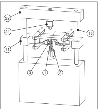
The machine presented in this article is part of the machines that use hydraulics for the application of alternating motion. Its main feature is the use of hydraulics for normal load application. Figure 1 shows a schematic diagram of the DEMAFtrib in tribometer configuration. The Device using Fatigue Machine as Tribometer (DEMAFtrib) converts a uni-axial fatigue machine into a biuni-axial fatigue machine. This device plays the role of the transversal axis added to the fatigue machine. It will enable normal force to be applied at the contact surface between the speci-men and pins. In the same manner as a conventional fatigue test, specimen (1) is driven by a reciprocating
1IUT de Figeac, ICA (Institut Cle´ment Ader), Universite´ de Toulouse,
France
2Mines Albi, ICA (Institut Cle´ment Ader), Universite´ de Toulouse,
France
Corresponding author:
M Cheikh, IUT de Figeac, ICA (Institut Cle´ment Ader), Universite´ de Toulouse, Avenue Nayrac, F-46100 Figeac, France.
movement of a fatigue machine actuator (called a lon-gitudinal actuator hereafter). The two pins (2) and (3) press the specimen with the same effort as the DEMAFtrib actuator. Friction and wear are created at the contact between the specimen faces and the two pins.
The ability to press the specimen symmetrically by the two pins is an original feature of this device. Each pin is attached to a load cell, which allows direct measurement of the force applied on the specimen.
Several configurations are possible with the device30:
. Case of machine use as a tribometer: in this case, the specimen is fixed from the longitudinal actuator side. The second end of the specimen is free. Force measurement is carried out by a sensor attached to the longitudinal actuator. Displace-ment amplitude is measured by the actuator displacement sensor.
. Case of fretting or fretting-wear: in this case, dis-placement amplitude is measured locally using an extensometer.
. Case of punching: this configuration is a combin-ation of an impact test and a wear test. This con-figuration has an advantage in the case of wear study of the coatings subjected to impacts. . The case of fretting fatigue: this configuration is a
combination of fatigue and wear with low displace-ment amplitude.
All these configurations are possible without any special modification of the fatigue machine. The DEMAFtrib is an accessory which can be assembled and dismantled at will, like any other accessory of a fatigue machine.
Device description
The device is shown in Figure 2 in multiple views. The device in open position is shown in Figure 2(a) and the device in closed position is seen from the front view in Figure 2(b) and (c). A sectional view of the device in a horizontal plane (plane A in Figure 2(b)) is shown in Figure 2(d). The device is carried by the crosspiece (11) which is fixed on the two columns (15) of a standard fatigue machine.
The device allows the pins (2–3) to press the speci-men (1) with a perfect symmetry in the form of a pinching motion. The system is composed of lifting beams (8–9), connecting rods (4–5) and the actuator (14). The lifting beams (8–9) transform the opening movement of the ram into a pinching movement of the pins against the specimen. The displacement of the two pins is free according to their axes. The movement of one pin is independent of the movement of the second pin. This freedom of movement with the symmetry of the pedals (8–9) and rods (4–5) allow self-centring of the system by the specimen.
The connection between supports (6–7) and cross-piece (11) is a sliding connection. The only possible movement of these materials, and thereafter the pins, is a translational motion. The pivot connection between the connecting rods (4–5) and the supports (6–7) allows the longitudinal force to be transmitted to the crosspiece (11) by the supports (6–7) only. The normal forces are not directly supported by the col-umns of the machine; instead, they are mainly sup-ported by the crosspiece (11). The pins’ axis is coplanar with the two columns axes. This co-planarity has the effect that no bending moment is applied to the columns of the machine. This, plus the fact that the normal forces are supported only by the crossbar (11), has the advantage that the machine works only in tension/compression in accordance with its normal use.
Normal force is measured by two transducers (16–17). The position of these two sensors close to the contact surfaces allows a direct measurement of normal force. Efforts such as parasitic friction forces in the joints of the system have no effect on measuring the normal force. Given the perfect symmetry of the device, measurement of normal forces by a single sensor is sufficient. The presence of two sensors pro-vides a perfect symmetry of geometry and inertia of the system. The measurement of normal forces by the second sensor monitors the system symmetry during the test. The observation of an asymmetry of the normal forces is a criterion, among others, of speci-men damage after heavy wear on the contact surfaces. Due to the geometric symmetry of the articulated system, alignment of pads is provided by the speci-men. The force applied by the left pad is equal to the force applied by the right one since the force applied on the two pads is provided by a single actuator.
The maximum load in the radial direction is 22,000 N. Two levels of cells are used for the meas-urement of the normal loading: a pair of cells with a capacity of 1500 N for the low-level loading and a pair of cells with a capacity of 25,000 N for the high level of normal loading. As the device is mounted on an MTS 810 machine, the maximum longitudinal loading is 100 kN with a displacement amplitude of 150 mm. For the measurement of low-level loading, as is the case in fretting wear, a cell of 5000 N capacity is used.
Wear configuration
The movement of the specimen is a reciprocating motion. It is considered that a test is in wear config-uration if a stroke distance is greater or equal to 4 mm, hence a displacement amplitude of !5 ! !"
with !"¼ 2mm. In this configuration, the
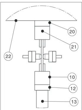
displace-ment amplitude is measured by the sensor actuator, generally of the linear variable differential trans-former (LVDT) type. This sensor measures a total value of displacement, including deformation due to machine flexibility. Given the rigidity of a fatigue machine, it is considered that this deformation is very small in respect to the actuator displacement, which is generally greater than 4 mm. To use the device in its first configuration as a tribometer, the force sensor (12) is attached to the longitudinal actu-ator (13). The mounting of the force sensor on the cylinder (13) permits measurement of the longitudinal force on the specimen. In this configuration, the upper
head (21) of the machine is not used and has no role, unlike in normal use of a machine fatigue.
Measuring axial and transverse loads gives a coef-ficient of friction (COF) of the materials in contact. This coefficient is the ratio of the tangential force, representing half the longitudinal force, and the normal force. Wear tests allow an evaluation of the volume or depth of wear. The wear depth can be measured directly by the displacement sensor of the transversal actuator (14). Wear depth is measured locally using the transversal extensometer (18) shown in Figure 3, which gives a more accurate wear value compared to the measurement obtained by the actuator sensor. Having a local measurement means that the value of the wear is not vitiated by the deformation of the system. Each arm of the extens-ometer is attached to a pin. If specimen hardness is very low compared to that of the pin, which is usually
(a) (b)
(c) (d)
Figure 2. Schematic of the DEMAFtrib: (a) device in open position, (b) device in closed position seen from the front, (c) zoom on D area of the front view, and (d) cross-sectional view of the device according to the horizontal plane A.
the case, measured wear corresponds to the specimen wear. The wear depth value w of each specimen face corresponds to half of the measurement given by the extensometer. Local measurement of the wear evolu-tion by in situ testing is an original feature of this machine. Indeed, for wear tests on POD-type tribom-eter, and more generally tribometers using dead loads as the normal force, wear evolution is measured at test’s end or through interrupted testing.
In the case where the device is used as a tribometer, several configurations are possible:
1. Case of ongoing pin press: in this case, wear is combined with tension, in a downward movement of the actuator, or with compression, in upward cycle of the actuator.
2. Case of pin support during traction and cancellation of normal effort during compression phase: This case is interesting where thin specimens are used, as it avoids their buckling under compression. 3. Case of punching: this is the case of wear combined
with impact. All combinations of impact, wear, ten-sion or compresten-sion are possible by acting on the control system. For example, impact may be at the beginning of a compression cycle if only an impact-compression-wear configuration is required, or at the beginning of a traction cycle for a tensile-impact-wear configuration. The special case of punching is interesting for coating characteriza-tion. In this configuration, wear measurement is not made by in situ testing with an extensometer, because for this type application, coating damage is generally caused by flaking and not wear.
Fretting or fretting-wear configurations
Displacements are very low in the case of fretting. Displacement amplitude in this case does not match the overall value measured by the longitudinal actu-ator’s sensor, as is the case in wear configuration. For fretting, the measurement of the displacement must be local in order to obtain a direct measurement of spe-cimen movement. With the DEMAFtrib, an extens-ometer can easily be added, making it possible to measure relative displacement between specimen and pins. Figure 4 shows the system that allows local measurement of the displacement !. One arm of the extensometer is fixed to a pin and the second arm is fixed to the upper part of the specimen. The upper part of the specimen is not deformed because it is not loaded. This allows a direct measurement of dis-placement between pins and specimen at contact level. In fretting maps, depending on the displacement amplitude value between pins and specimen, two cases can be considered31:1. Partial slip regime: in this case, the damage type of the contact materials is usually cracking. The wear
measurement in this case is not very significant. For our study, this case corresponds to a fretting configuration.
2. Gross sliding regime: in this case, the damage of contact surfaces is mainly of the wear type. In this instance, it is necessary to measure wear evolution with displacement amplitude evolution. For our study, this configuration corresponds to the case
of fretting-wear (the distinction between wear,
fretting or fretting-wear configurations is not based on any standard. It is a rule of customary we chose to use the machine).
Figure 5 presents the fretting-wear case where dis-placement amplitude values and wear depth are simul-taneously measured. The extensometer (18) measures the wear depth 2w and the extensometer (19) measures the value of the displacement !.
Fretting-fatigue configuration
The fretting fatigue is obtained by combining fretting with fatigue loading. Two variants of the fretting-fati-gue configuration are possible with the DEMAFtrib: 1. Loading fatigue in transversal direction (normal direction to specimen surface contact): instead of
Figure 4. Longitudinal extensometer attachment in fretting configuration.
Figure 5. Longitudinal and transversal extensometers attachment in fretting-wear configuration.
imposing a constant normal force, as is the case in fretting presented in section ‘‘Fretting or fretting-wear configurations’’, the transversal actuator (14) applies a variable force on the pins. This first vari-ant of fretting-fatigue corresponds to the radial fretting32simulating structure subjected to fatigue
loading in normal direction to contact surface. Such fretting mode is frequently encountered in many fitted assemblies under vibration condition. For instance, various rivet joints, fuel rod/spring contact in pressurized water reactors, adjacent tubes in steam generators, ball bearings, leaf springs used in automobiles, railway rolling stocks and electrical contacts are more or less associated with such type of fretting.
2. Loading fatigue in longitudinal direction: Figure 6 shows a principle diagram of the device in the second variant of the fretting-fatigue configur-ation. In this case, friction is combined with a conventional fatigue test. The fixed specimen between the two heads of the machine is subjected to a fatigue test. To create friction, the pins (2–3) apply a constant normal force N on the specimen.
To measure the tangential force, in addition to the force sensor (12) attached to the longitudinal actuator (13), the fixed head (21) of the machine is equipped with a force sensor (20). The tangential force Q is calculated from efforts F1and F2measured by sensors
(12) and (20), hence:
Q¼F1$ F2 2 ð1Þ
The displacement value ! is measured by an extens-ometer. An arm of this extensometer is fixed with a pin. The second arm is attached to the specimen. The displacement value can be obtained directly if we choose a specimen shape that allows the arms of the extensometer to be fixed in front of the pin, as shown in Figure 7. If the specimen shape does not allow the extensometer’s arm to be fixed in front of the pin, the assembly shown in Figure 8 can be chosen. In this case, the specimen elongation corresponding to length A must be subtracted to obtain an exact dis-placement value. The disdis-placement value is also the measurement given by the extensometer if a specimen shape of the type shown in Figure 9 is chosen. For this type of test, one considers that the specimen extends only into the central area, which corresponds to the value measured by the extensometer.
The displacement value is proportional to fatigue loading. To vary this displacement without varying the fatigue-loading value, the geometry of the specimen can be varied (section or length). The displacement may be varied also with the pin’s verti-cal position corresponding to the B dimension. Displacement reaches its maximum when approach-ing the pins on the lower head of the machine and vanishes when approaching the pins on the upper head of the machine. The DEMAFtrib can control the fretting-fatigue test by force or displacement,
Figure 6. Fretting-fatigue configuration. A
B
F1
F2
Figure 8. Extensometer attachment in second alternative. Figure 7. Extensometer attachment in first alternative.
which represents an advantage for a fretting-fatigue test.
Compared to the rigs mounted on fatigue machines used in literature,19,20,23–25DEMAFtrib differs by the use of hydraulic to impose the normal force with a single actuator. DEMAFtrib differs also by its ability to impose either a radial or a longitudinal loading fatigue.
DEMAFtrib command system
DEMAFtrib control requires a controller to the ser-voactuator control loop and a maximum of five data-acquisition channels. There is no need for a specific controller; one can simply use the channels available on the controller of the fatigue machine. For all DEMAFtrib configurations, the FlexTest SE control-ler made by MTS was used and there was no need for any additional electronics.
For controlling displacement or normal force, the DEMAFtrib uses the possibilities offered by the con-trol system of the machine fatigue. The concon-trol signal shape can be constant, sinusoidal, square, ramp, etc. Instead of driving the test by displacement or by force, any combination of these can be used as calcu-lated channels. This option allows the test to be con-trolled by pressure and not by force, for example.
On tribometers of type POD or LRBF, the contact pressure is not constant in relation to the wear evolu-tion. Thus, if a load in the form of displacement is imposed, the force value, and then the contact pres-sure, will decrease with the increase in wear. In a simi-lar way, if a constant load is imposed, such as a dead load for example, the pressure value changes with wear evolution.
To overcome the problem of change in contact pressure, the DEMAFtrib uses the calculated chan-nels to control the wear tests. Instead of imposing a
constant force, a constant pressure of type P¼ N=S
can be imposed with N the normal force applied on the contact and S the value of contact area. The con-troller will apply a variable force N depending on the variation in the contact surface in order to obtain a
constant pressure. The value of the contact area will be calculated automatically by the controller. For example, in the case of a sphere-on-flat specimen, the contact area depends on the stages of the test: 1. At the start of the test, the wear value is very
low and the contact area is given by:
S¼ "a2 ð2Þ
with a the radius of contact area33 defined by:
a¼pffiffiffiffiffiffiffiwR ð3Þ
with w the indentation depth corresponding to half of the value measured by the transversal extensom-eter and R the radius ball. If the wear value reaches the critical value:
w5wc ð4Þ
with wc the critical level of wear from which it is
considered that the contact is of sphere-on-groove type and not sphere-on-flat. The contact area takes on an elliptical shape:
S¼ "ab ð5Þ
with: b¼ R arccosððR $ wÞ=RÞ.
The values of contact area S (equation (2) or equa-tion (5)) and the applied force N will be calculated continuously according to the degree of indentation, or w wear, in order to have the desired constant pres-sure. With the same approach used to apply pressure,
any combination of type fðN, w, !, F1, F2Þ can be
applied, which opens up a wide field of applications in fretting and wear characterization of materials.
Applications
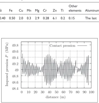
As an example of application of the use of DEMAFtrib as a tribometer or a fretting machine, a sample of study results of the wear and fretting of 7075 aluminium alloy is presented below. The metal-lurgical index of the used 7075 alloy is T7351. The chemical composition of the material used is pre-sented in Table 1. The specimen has a prismatic
cross–section of 12' 36 mm and a length of
220 mm. The pins used in the study are balls of 100Cr6 with a 12 mm diameter. The two contact sur-faces are polished with abrasive paper with three sizes: 380, 600 and 1200 to reach a surface of Ra¼ 0.2 mm.
Wear characterization of the 7075 aluminium alloy
The displacement of the reciprocating movement ofthe specimen is !"¼5 mm with a frequency of
0.5 Hz. The duration of the wear test is 5' 103
cycles. The normal load is applied as a constant
pressure of P¼ 49 MPa. Figure 10 shows the imposed pressure value and Figure 11 shows the contact-area and the normal force evolutions according to dis-tance. The imposed force is not constant; it varies from 50 N to 300 N, depending on the wear of the contact surface. Two typical friction cycles in this test are shown in Figure 12. Cycle 5 is representative of the first cycles of the test. The apparent friction
coefficient #¼ Q=N is constant at the beginning of
the test. With the evolution of wear, horizontal seg-ments of the friction cycles become oblique. The fric-tion coefficient is not the same at the beginning (m min) and at the end (m max) of each segment. The COF evolution is shown in Figure 13.
Wear variation in relation to the number of test cycles is shown in Figures 14 and 15. The last figure shows the evolution of maximum and minimal wear for each cycle, according to the evolution of the test. River wear shown in Figure 14 reveals the evolution of wear according to the total sliding distance and displacement !.
Fretting characterization of the 7075
aluminium alloy
For the fretting test, a constant force of 200 N is applied as a normal load. For the fretting character-ization of 7075 aluminium alloy, two cases of dis-placement are used: a disdis-placement of !" ¼ 3:5 mm in the first case and a displacement of !"¼ 25 mm for the
second case. The durations of the test are 1' 103
cycles and 5' 105 cycles for the first and the second
tests, respectively. In both cases, the test frequency is 5 Hz. Figures 17 and 16 show fretting cycles for
both cases. The first case corresponds to partial slip regime; it cannot characterize the COF. The second case corresponds to total slip regime. In this case, the starting COF is 0.15. The shape of the fretting cycles evolves with the sliding distance. The fretting cycles
–1.5 –1 –0.5 0 0.5 1 1.5 2 Q /N δ(mm) cycle 5 cycle 5k –6 –4 –2 0 2 4 6
Figure 12. Friction cycles at the beginning of the test (cycle 5) and the 5000th cycle friction (cycle 5 k).
0 1 2 3 4 5 6 7 8 0 10 20 30 40 50 60 70 80 90 1000 50 100 150 200 250 300 350 Con tact sur face (mm 2) N or m al fo rce (N ) distance (m) normal force contact surface
Figure 11. Evolutions of normal force and contact surface with the sliding distance.
0.2 0.3 0.4 0.5 0.6 0.7 0.8 0.9 1 µ = Q /N distance (m) µ max µ min 0 10 20 30 40 50 60 70 80 90 100
Figure 13. COF evolution at the beginning (min) and at the end (max) of each segment of friction.
48.4 48.6 48.8 49 49.2 49.4 49.6 49.8 Imp osed pression P (MP a) distance (m) Contact pression 0 10 20 30 40 50 60 70 80 90 100
Figure 10. Applied pressure evolution in the wear test. Table 1. Chemical composition of the 7075-T7351 aluminum alloy.
Si Fe Cu Mn Mg Cr Zn Ti Other
elements Aluminum 0.40 0.50 2.0 0.3 2.9 0.28 6.1 0.2 0.15 The last
become stable after the 50,000th cycle and stabilized
COF exceeds the set of m ¼ 1. Figure 18 shows the
COF evolution with the sliding distance. In this figure, m min corresponds to the isotropic coefficient of
friction of the KI-COF model.34 In the total slip
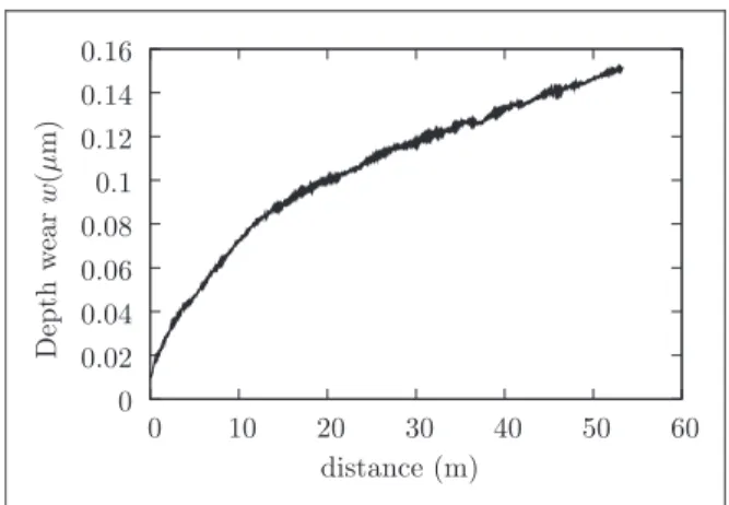
regime, wear evolves with the sliding distance, as shown in Figure 19. The COF stabilizes from a sliding distance of 20 m, and wear continues to increase. distance (m) δ(mm) 0 10 20 30 40 50 60 70 80 90 100 –4 –2 0 2 4 –4.5–4 –3.5–3 –2.5–2 –1.5–1 –0.5 0 0.5 wear depth w (mm x 10 –1 ) –4.5 –4 –3.5 –3 –2.5 –2 –1.5 –1 –0.5 0 0.5
Figure 14. Wear river in the case of P¼ 49 MPa and d*
¼ 5 mm wear test. –0.8 –0.6 –0.4 –0.2 0 0.2 0.4 0.6 0.8 Q /N δ(µm) cycle 1k –5 –4 –3 –2 –1 0 1 2 3 4 5
Figure 16. Fretting cycles for !"¼ 3: 5 mm and N ¼ 200 N
(case 1). 0.2 0.3 0.4 0.5 0.6 0.7 0.8 0.91 1.1 1.2 µ = Q /P distance (m) µ max µ min 0 10 20 30 40 50 60
Figure 18. COF evolution in the case of N¼ 200 N and
!"¼ 25 mm fretting test. –0.1 0 0.1 0.2 0.3 0.4 0.5 0.6 0 10 20 30 40 50 60 70 80 90 100 W ea r dep th w (mm) distance (m) wmax wmin
Figure 15. Maximum and minimum wear for each cycle of
friction in the case of P¼ 49 MPa and d*
¼ 55 mm wear test. –1.5 –1 –0.5 0 0.5 1 1.5 –30 –20 –10 0 10 20 30 Q /N δ(µm) Cycles 5 100 500 5k 50k 100k 400k
Figure 17. Fretting cycles for !"¼ 25 mm and N ¼ 200 N
Conclusion
This article presents an apparatus used as an acces-sory to a fatigue machine, which enables the latter to be used as a tribometer. This device also makes it possible to use a standard fatigue machine as a fret-ting machine. In tribometer configuration, the machine can apply high-level loads and long strokes exceeding 100 mm. For fretting purposes, the machine can be used as a fretting-wear or fretting-fatigue machine. In the case of fretting-fatigue, the direction of fatigue loading may be normal in relation to the contact surface, thus providing a radial fretting vari-ant. All these possibilities are offered by this device without any modification of the machine. It is used like any other accessory machine which can be
installed or removed at will according to
requirements.
The last section of this paper presents an example of the machine use with a wear-test sample and a fretting-test sample. These two examples show that this machine can be used like any other fretting machine or tribometer for the characterization of materials under fretting or wear.
Funding
This study is sponsored by Conseil Re´gional Midi-Pyre´ne´e (CRMiP).
Acknowledgements
The authors wish to thank M. Malvy, President of CRMiP, for his support to the growth of research activities at the IUT of Figeac. The authors are grateful to P. Tirache (of IUT Figeac) for the manufacturing of certain parts of the machine and to J. Lample (of IUT Figeac) for the electrical wiring of the machine.
References
1. ASTM-G99-05(2010). Standard test method for wear
testing with a pin-on-disk apparatus. ASTM
International, 2010.
2. ASTM-G133-05(2010). Standard test method for lin-early reciprocating ball-on-flat sliding wear. ASTM International, 2010.
3. Waterhouse RB. Fretting fatigue. Int Mater Rev 1992; 37: 77–97.
4. Neu RW. Progress in standardization of fretting fatigue terminology and testing. Tribol Int 2011; 44: 1371–1377.
5. Kayaba T and Iwabuchi A. Effect of the hardness of hardened steels and the action of oxides on fretting wear. Wear 1981; 66: 27–41.
6. Waterhouse RB, McColl IR, Harris SJ, et al. Fretting wear of a high-strength heavily work-hardened eutec-toid steel. Wear 1994; 175: 51–57.
7. Dubourg MC, Chateauminois A and Villechaise B. In situ analysis and modeling of crack initiation and propagation within model fretting contacts using poly-mer materials. Tribol Int 2003; 36: 109–119.
8. Zhang DK, Ge SR and Qiang YH. Research on the fatigue and fracture behavior due to the fretting wear of steel wire in hoisting rope. Wear 2003; 255: 1233–1237.
9. Ramesh R and Gnanamoorthy R. Development of a fretting wear test rig and preliminary studies for under-standing the fretting wear properties of steels. Mater Des 2006; 27: 141–146.
10. Okado J, Shima M, McColl IR, et al. Ni-P and Mo: an excellent fretting wear resistant combination. Wear 1999; 225–229: 749–757.
11. Sato J, Shima M, Sugawara T, et al. Effect of lubricants on fretting wear of steel. Wear 1988; 125: 83–95. 12. Koenen A, Virmoux P, Gras R, et al. A machine for
fretting fatigue and fretting wear testing in cryotechni-cal and normal environment. Wear 1996; 197: 192–196. 13. Tricoteaux A, Jouan PY, Guerin JD, et al. Fretting
wear properties of CrN and Cr2N coatings. Surf Coat
Technol 2003; 174–175: 440–443.
14. Leonard BD, Sadeghi F, Shinde S, et al. A novel mod-ular fretting wear test rig. Wear 2012; 274–275: 313–325.
15. Marui E, Endo H, Hasegawa N, et al. Prototype fret-ting-wear testing machine and some experimental results. Wear 1998; 214: 221–230.
16. Bathias C. Piezoelectric fatigue testing machines and devices. Int J Fatig 2006; 28: 1438–1445.
17. Barril S, Debaud N, Mischler S, et al. A tribo-electrochemical apparatus for in vitro investigation of fretting-corrosion of metallic implant materials. Wear 2002; 252: 744–754.
18. Nowell D and Hills DA. Crack initiation criteria in fretting fatigue. Wear 1990; 136: 329–343.
19. Wittkowsky BU, Birch PR, Dominguez J, et al. An apparatus for quantitative fretting testing. Fatig Fract Eng Mater Struct 1999; 22: 307–320.
20. Mugadu A, Hills DA and Nowell D. Modifications to a fretting-fatigue testing apparatus based upon an ana-lysis of contact stresses at complete and nearly complete contacts. Wear 2002; 252: 475–483.
21. Jin O and Mall S. Effects of slip on fretting behavior: experiments and analyses. Wear 2004; 256: 671–684.
22. Szolwinski MP and Farris TN. Observation, analysis and prediction of fretting fatigue in 2024-T351 alumi-num alloy. Wear 1998; 221: 24–36.
0 0.02 0.04 0.06 0.08 0.1 0.12 0.14 0.16 0 10 20 30 40 50 60 Depth w ear w (µ m) distance (m)
Figure 19. Wear depth evolution for a fretting test with
23. Cortez R, Mall S and Calcaterra JR. Investigation of variable amplitude loading on fretting fatigue
behavior of Ti-6Al-4V. Int J Fatig 1999; 21:
709–717.
24. Gean MC and Farris TN. Elevated temperature fretting fatigue of Ti-17 with surface treatments. Tribol Int 2009; 42: 1340–1345.
25. Magaziner R, Jin O and Mall S. Slip regime explanation of observed size effects in fretting. Wear 2004; 257: 190–197.
26. Kubiak K, Fouvry S, Marechal AM, et al. Behaviour of shot peening combined with WC-Co HVOF coating under complex fretting wear and fretting fatigue loading conditions. Surf Coat Technol 2006; 201: 4323–4328.
27. Wallace JM and Neu RW. Fretting fatigue crack nucle-ation in Ti-6Al-4V. Fatig Fract Eng Mater Struct 2003; 26: 199–214.
28. Pape JA and Neu RW. Influence of contact configur-ation in fretting fatigue testing. Wear 1999; 225–229: 1205–1214.
29. Arora PR, Jacob MSD, Salit MS, et al. Experimental evaluation of fretting fatigue test apparatus. Int J Fatig 2007; 29: 941–952.
30. Cheikh M, Fermy A, inventors; Toulouse University II, assignee. Versatile device research of mechanical proper-ties of a specimen. Patent FR2971845, 2012.
31. Fouvry S, Kapsa P and Vincent L. Quantification of fretting damage. Wear 1996; 200: 186–205.
32. Zhu MH and Zhou ZR. An experimental study on radial fretting behaviour. Tribol Int 2001; 34: 321–326. 33. Johnson KL. Contact mechanics. London: Cambridge
University Press, 1985.
34. Cheikh M, Quilici S and Cailletaud G. Presentation of KI-COF, a phenomenological model of variable friction in fretting contact. Wear 2007; 119: 15–19.